Compact millimeter-wave air-filled substrate-integrated waveguide crossover employing homogeneous cylindrical lens*#
Chun GENG ,Jiwei LIAN ,Dazhi DING
1Qian Xuesen College, Nanjing University of Science and Technology, Nanjing 210094, China
2School of Microelectronics (School of Integrated Circuits), Nanjing University of Science and Technology, Nanjing 210094, China
3State Key Laboratory of Millimeter Waves, Southeast University, Nanjing 210096, China
We propose a new method to design crossovers by employing an embedded homogeneous cylindrical lens (HCL).Compared with traditional crossover designs,this strategy introduces an HCL within the air-filled substrate-integrated waveguide (SIW) crossover cavity to direct the incident waves in the desired direction.According to ray-tracing analysis,the added HCL can efficiently concentrate the electromagnetic wave propagating from the input to the output without increasing the fabrication complexity or footprint.The operating mechanism of this method is elaborated in detail,and is further verified by E-field distributions.Using the air-filled SIW technology,two-,three-,and four-channel crossovers operating at the millimeterwave are developed and fabricated to demonstrate the practical feasibility of the proposed method.Some transitional structures are designed for experimental purposes.It is found that the simulated fractional bandwidths (FBWs) related to two-,three-,and four-channel air-filled SIW crossovers are 33%,14%,and 10%,respectively;the dimensions of their core areas are 0.74λ×0.74λ,1.43λ×1.43λ,and 1.90λ×1.90λ,respectively.Comparisons between our method and similar approaches in the literature illustrate the advantages of our method.
1 Introduction
Most reported crossovers operating at the microwave frequency are based on microstrip technology because of its merits of planar structure and ease of integration (Feng et al.,2016;Jiao et al.,2018;Tajik et al.,2018;Yu and Sun,2019).Recently,millimeterwave and terahertz applications have attracted great interest due to the higher availability of unallocated frequency spectrum resources.In this situation,some close or quasi-close structures are preferable in crossover designs,which include waveguide (Cheng et al.,2021),substrate-integrated waveguide (SIW) (Djerafi and Wu,2009;Hesari and Bornemann,2017;Sun et al.,2020;Qi et al.,2021),and printed ridge gap waveguide (Ali and Sebak,2018).
Traditional crossovers usually comprise four ports and deal with the intersections between two channels.As the circuit complexity increases,intersections among more than two channels appear and they should be taken into account in circuit designs.One feasible alternative is to cascade multiple two-channel crossovers.For instance,three two-channel crossovers can be combined into a three-channel crossover,or six two-channel crossovers can cooperatively build a four-channel crossover.However,apparently too many two-channel crossovers are required and cascaded in these cases,which can lead to larger sizes and increased losses (Li and Luk,2016).
Facing this issue,the design of crossovers dealing with more than two channels simultaneously has become a significant and challenging research topic.Tang and Chuang (2015) used double rings in the microstrip to construct a three-channel crossover,which was later extended to a four-channel crossover (Chu and Tang,2018).Wu et al.(2014) proposed a different three-channel crossover by using lumped inductors.Subsequently,a microstrip three-channel crossover with the filtering property was developed (Wu and Mao,2016).However,for reasons explained above,these crossovers in the microstrip technology are not suitable for millimeter-wave or above millimeter-wave applications.
Some crossovers have been proposed that use close or quasi-close transmission lines.Using a cavity for excitation TE011,TE101,and TM110modes (Lin et al.,2019),a three-channel waveguide filtering crossover was reported at the expense of a large size.Lian et al.(2020) designed a four-channel crossover using SIW technology by adding a power divider to each port,which eventually led to a larger footprint.When resorting to TE102and TE201modes,four-,five-,and sixchannel SIW filtering crossovers have been realized.To support the TE102and TE201modes simultaneously,the whole design is formed by cascaded rectangular cavities,while it suffers from a relatively large footprint (Zhan et al.,2020;Zhou and Wu,2020).
Given the state-of-the-art development of crossovers,a new method to design air-filled SIW crossovers using an embedded homogeneous cylindrical lens (HCL) was proposed by Geng et al.(2022).In previous studies,HCLs (two-dimensional case) or homogeneous spherical lenses (three-dimensional case) have been widely applied and explored in antenna designs (Bekefi and Farnell,1956;Gunderson,1972;Schoenlinner et al.,2002;Boriskin et al.,2008;Costa et al.,2009;Zhang et al.,2011).As for the antenna design,the introduced HCL enables the conversion from spherical or cylindrical wave to planar wave,so that a high-directivity radiation can be achieved.Meanwhile,the feasibility of such lens in crossover designs is still questionable.In the proposed crossover design,the introduced HCL helps concentrate the electromagnetic wave and suppress the wave scattering within the airfilled SIW crossover cavity.Compared with previously published designs,the proposed method has mainly three salient merits.Firstly,this method drills an airfilled area to build an HCL without increasing the crossover footprint.Secondly,it is applicable to the two-channel crossover and can be extended to three-,four-channel crossovers,etc.Thirdly,it can be applied in single-layer SIW technology,which serves as an attractive candidate for low-loss and highly-integrated millimeter-wave applications.
2 Air-filled SIW crossover design
2.1 Operation principle
Fig.1 depicts the topology of the proposed method for two-,three-,and four-channel crossovers.For the simplest case,it is composed of four ports (two channels).Different from traditional crossover designs,an extra HCL is inserted at the intersection.As a result,the electromagnetic wave coming from port 1 as an example will exclusively propagate toward port 3,while satisfactory isolation is observed between port 1 and port 2 (port 4).This two-channel topology can be extended to three-and four-channel cases by adjusting the diameters of the crossover cavity and the inserted HCL.
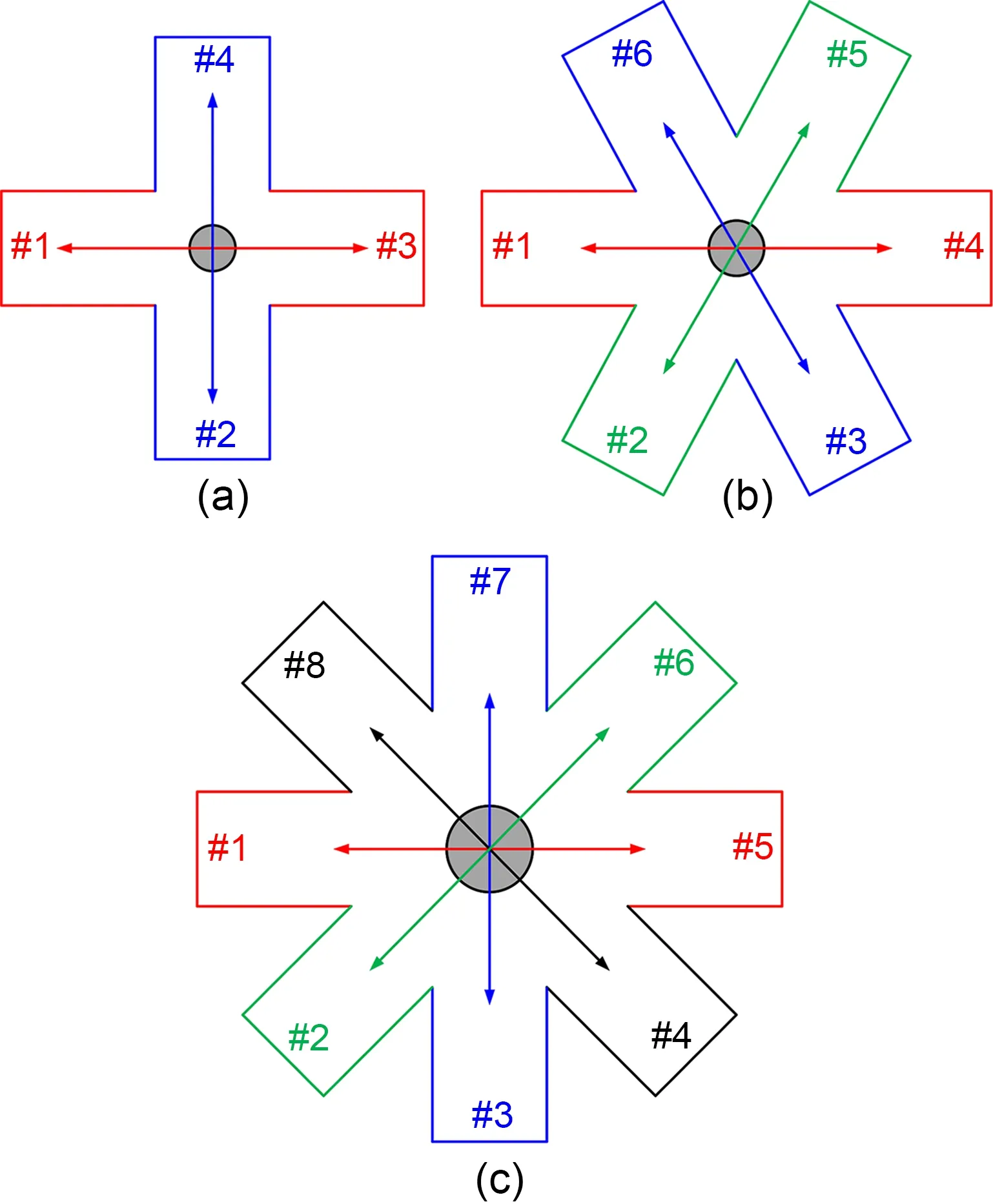
Fig.1 Topologies of two-channel (a),three-channel (b),and four-channel (c) crossovers
Fig.2a describes the design parameters from both the top view and side view.The width of the open air-filled SIW is denoted bywand the thickness of the substrate ish;ais the radius of the HCL,whiler0is the distance between the input air-filled SIW and the center of the HCL.The relative dielectric constants inside and outside the HCL are indicated byεr2andεr1,respectively.

Fig.2 Design parameters of the HCL (a) and ray-tracing analysis of the crossover with HCL (b)
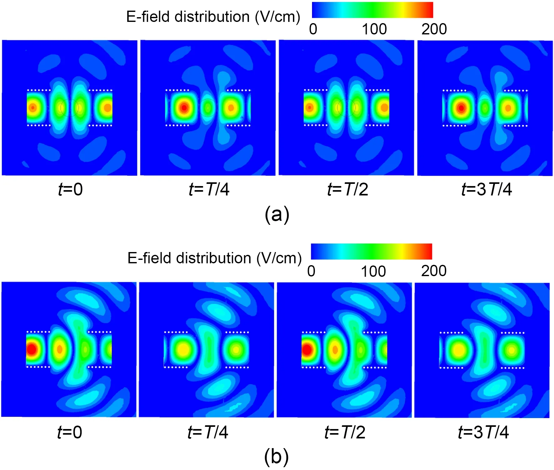
Fig.3 E-field distribution with (a) and without (b) HCL at 30 GHz (T is the period of the electromagnetic field)
To further reveal the operation mechanism of the proposed method,the ray-tracing analysis of the crossover with HCL is displayed in Fig.2b.Lian et al.(2020) demonstrated that concentrating the incoming electromagnetic wave is an effective method to design crossovers,which introduces a power divider at each port,so that the electromagnetic wave is concentrated.At the same time,the added power dividers lead to a larger footprint.In contrast,the proposed topology with an embedded HCL has the merit of better compactness,which is an alternative to concentrating the electromagnetic wave.In this case,the ray escaping out of the HCL should be parallel to thex-axis,as shown in Fig.2b.In contrast,when designing a crossover,each ray encountering two refractions is expected to arrive at the position mirrored to the source point,as shown in Fig.2b.
按照“厚基础、强应用、有特色”的原则,精简课程体系,设置实用性、前沿性强的专业课程,补齐短板,增加关联大、交叉多的基础课程开设,打破专业与学科之间的横向壁垒,积极开发综合性特色课程。通过调研学生对知识的多层次需求,适当增加选修课数量,满足学生全面发展的需要。从全面提升和完善学生的科学文化素养、合理的知识结构和创新创业实践能力出发,制订符合社会需要的教学大纲和教学计划,确定教学内容,[5]鼓励教师将最新学术动态、技术成果和创新经验融入课堂教学。
The above is a brief description of the operation mechanism of the proposed method,and a more detailed description can be found in Section 1 of the supplementary materials.More details about this result can be found in (Gunderson,1972).
To give a clearer view of the impact brought by the HCL,we compute the model using the High-Frequency Structure Simulator (HFSS) and show the E-field distribution,and the results contains two open air-filled SIWs with or without an HCL.As depicted in Figs.3a and 3b,it is observed that the E-field is bound in the HCL and most of the incoming energy propagates toward the other port.In contrast,if the HCL was removed,the energy would scatter outward and severe energy leakage would appear.
2.2 Design process
Derived from the abovementioned topology,a two-channel air-filled SIW crossover is designed,as shown in Fig.4a,wherea1is the radius of the HCL of the two-channel crossover,d1is the distance between the centers of two adjacent metal holes,andd2is the diameter of the metal holes.The first step of the design procedure is to determine the relative dielectric constants inside and outside the HCL.To simplify the fabrication,an air-filled area is built by drilling the substrate.In this way,one can obtain an interface between two materials within a single substrate.Here,a Rogers RT/duroid 5880 substrate with a thickness of 0.787 mm is applied.Then,we haveεr1=1.0 andεr2=2.2.Secondly,the width of the open air-filled SIWwshould be large enough to support the dominant mode within the interested frequency spectrum.In this work,w=7.2 mm is chosen.Then,one open air-filled SIW should be duplicated to four and placed clockwise to build a closed cavity.Finally,an HCL is inserted at the center and its diameter is optimized to achieve the minimum reflection and isolation.
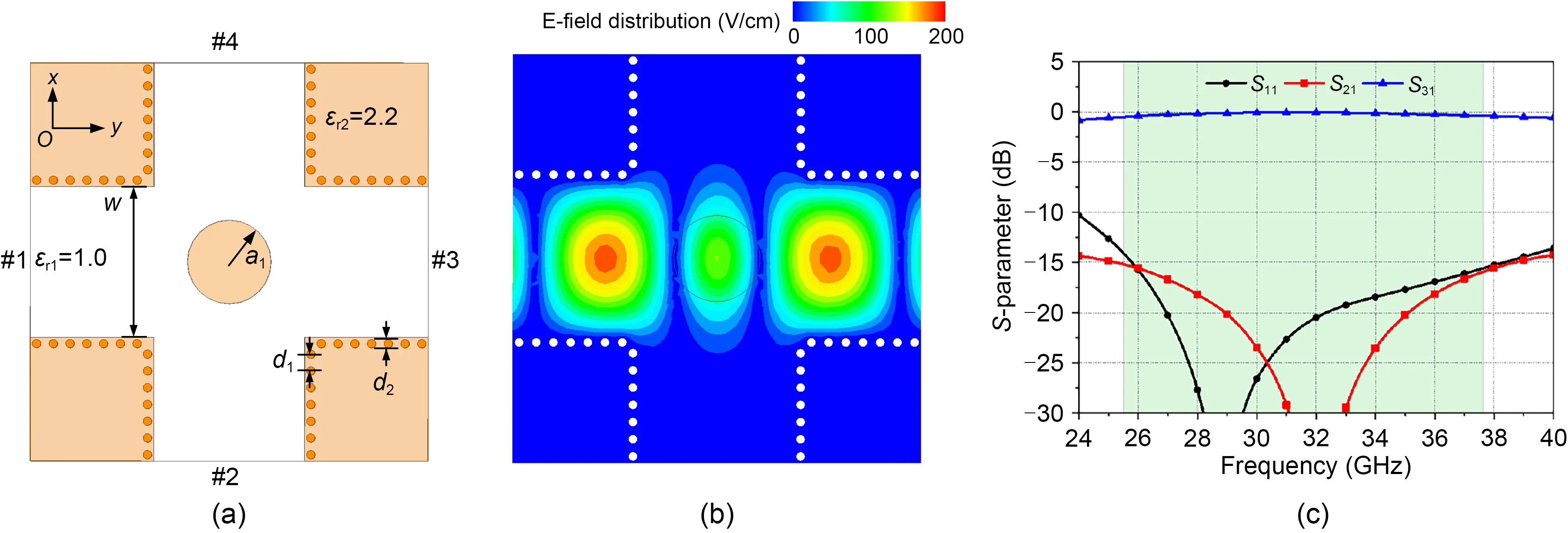
Fig.4 Simulated HFSS model (a),E-field distribution (b),and S-parameters (c) of the two-channel SIW crossover (d1=0.80 mm,d2=0.40 mm, a1=2.00 mm,and w=7.20 mm)
The E-field distribution of the designed twochannel crossover at 30 GHz is displayed in Fig.4b,in which a crossed transmission is observed.The simulatedS-parameters of the designed two-channel crossover are plotted in Fig.4c,whereS11is the reflection coefficient of port 1,S21is the isolation coefficient of port 1 and port 2,andS31is the isolation coefficient of port 1 and port 3.From 25.8 to 38.3 GHz,the reflection coefficient and the isolation coefficients are lower than -15 dB,indicating a fractional bandwidth (FBW) of 39%.Within this frequency range,the insertion loss varies from 0.1 to 0.5 dB.
To describe the design process more clearly,parametric study is given in Section 2 of the supplementary materials.In the above,the design details of the twochannel air-filled SIW crossover have been elaborated.Interestingly,the proposed method can be directly extended to crossovers with more channels.As shown in Fig.5a,a three-channel air-filled SIW crossover is designed using the proposed topology.Since the design process and operation principle are similar to those in the two-channel case,only the final model and simulation results are provided here.The E-field distribution at 34 GHz is displayed in Fig.5b,in which a crosspassing property is observed.The optimalS-parameters are plotted in Fig.5c.Due to the symmetry of the configuration,S51andS61are omitted.From 31.9 to 36.6 GHz,both the reflection and isolation coefficients are less than -15 dB;i.e.,the FBW is 14%.Within this frequency range,the minimum and maximum transmission losses are 0.1 dB and 0.7 dB,respectively.
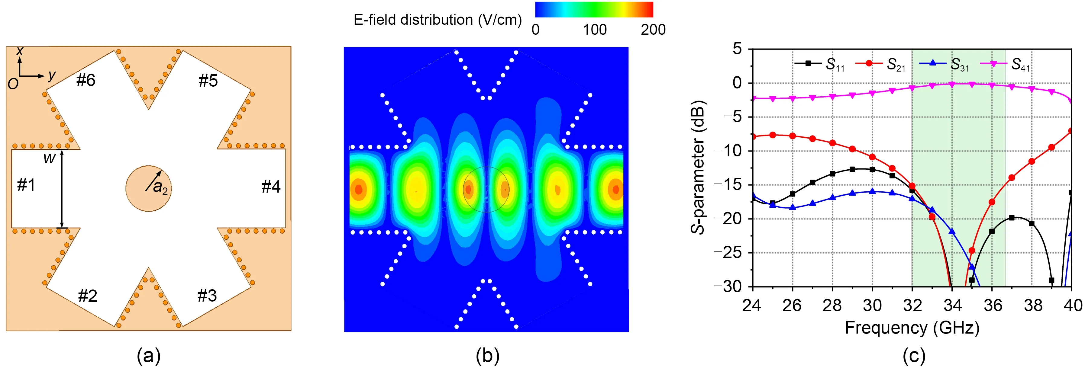
Fig.5 Simulated HFSS model (a),E-field distribution (b),and S-parameters (c) of the three-channel SIW crossover (a2=2.10 mm,w=7.20 mm)
Similarly,a four-channel counterpart is designed (Fig.6a),and its E-field distribution is shown (Fig.6b).Indicated by theS-parameters in Fig.6c,the FBW is 7.5% (32.0 to 34.5 GHz).The minimum insertion loss is 0.2 dB,while the maximum insertion loss is 0.7 dB.
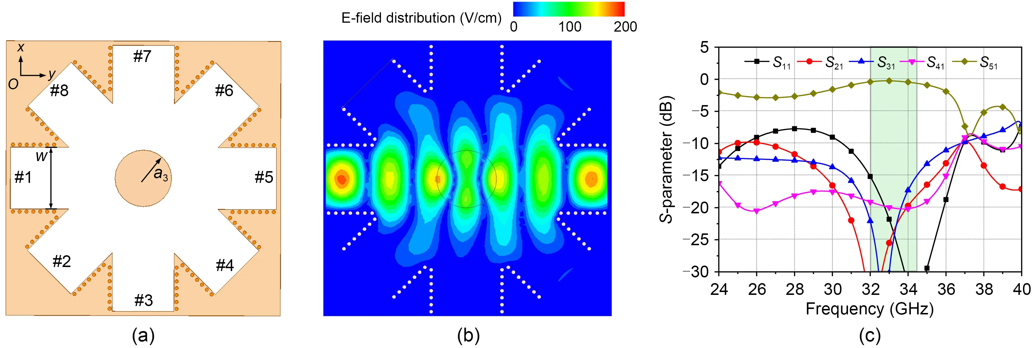
Fig.6 Simulated HFSS model (a),E-field distribution (b),and S-parameters (c) of the four-channel SIW crossover (a3=4.00 mm,w=7.20 mm)
3 Results and discussion
3.1 Simulation and measurement
For the experiments,transitions from SIW to airfilled SIW and coplanar waveguide (CPW) to SIW are designed,as shown in Fig.7a (Parment et al.,2015).The simulated reflection and transmission coefficients are plotted in Fig.7b.From 25.9 to 41.6 GHz,the reflection coefficient is below -15 dB,corresponding to a maximum insertion loss of 0.8 dB and a minimum insertion loss of 0.4 dB.The fabricated prototypes of the two-,three-,and four-channel air-filled SIW crossovers are shown in Fig.8.The interior,top,and bottom views are illustrated in Figs.8a-8c.Two aluminum plates are added on the top and bottom of the substrate to act as ground planes.The design parameters of the crossover are listed in Table 1.
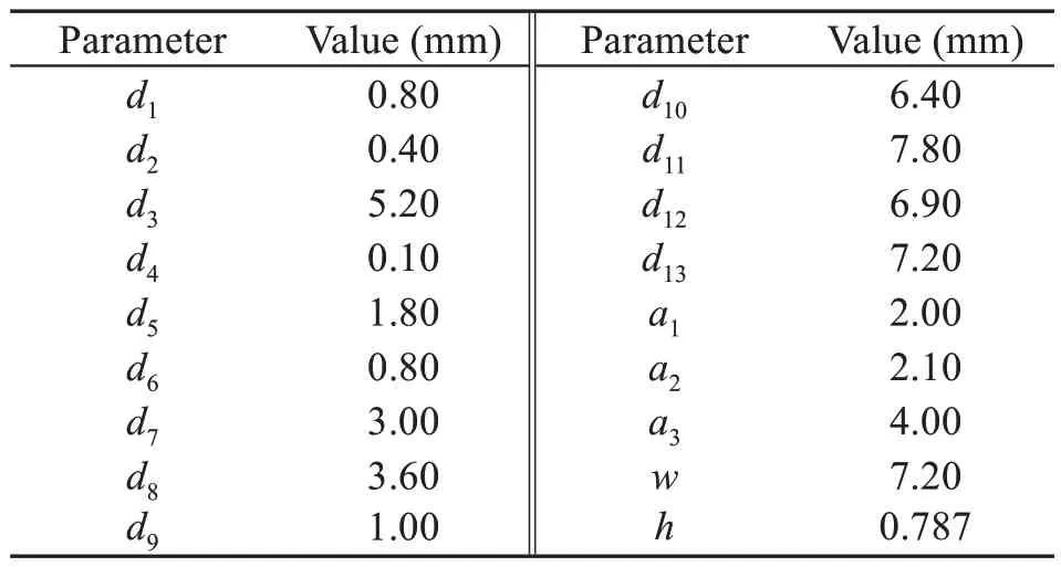
Table 1 Design parameters and values
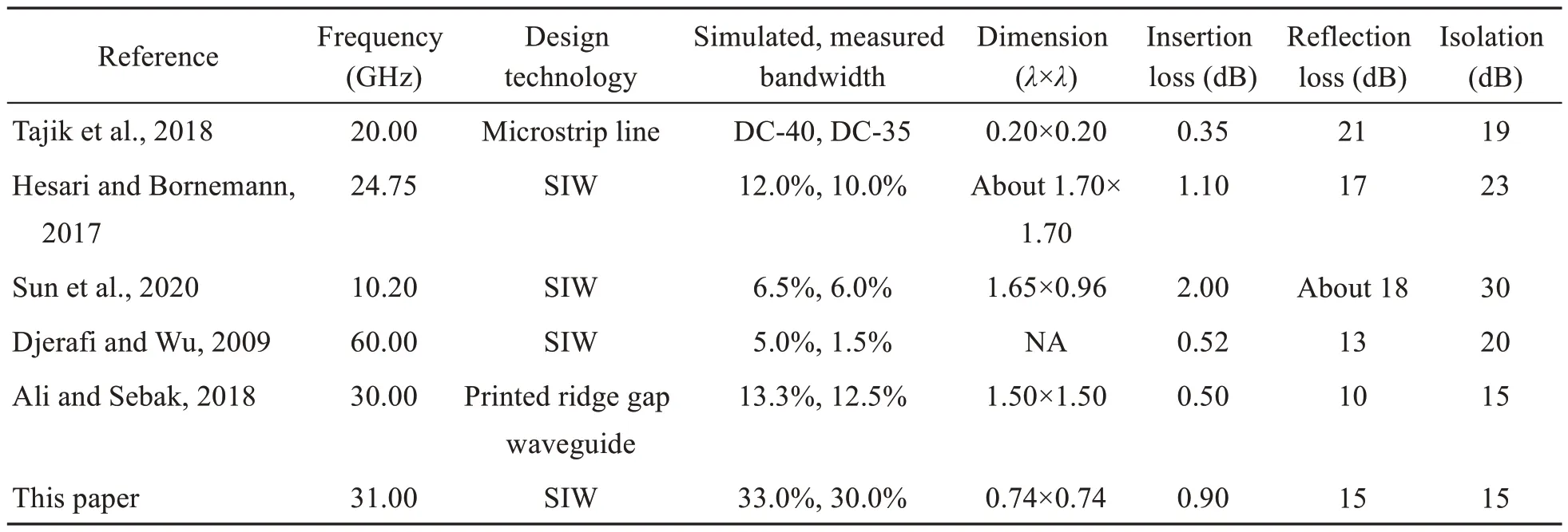
Table 2 Comparisons between the designed two-channel crossovers and similar designs
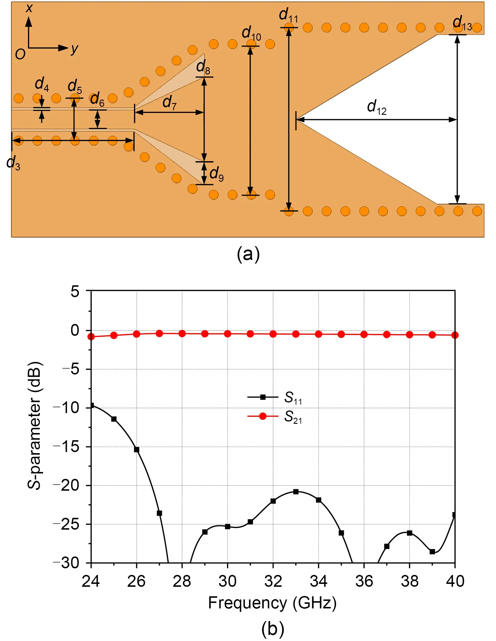
Fig.7 Simulated HFSS model (a) and S-parameters (b) of the transition
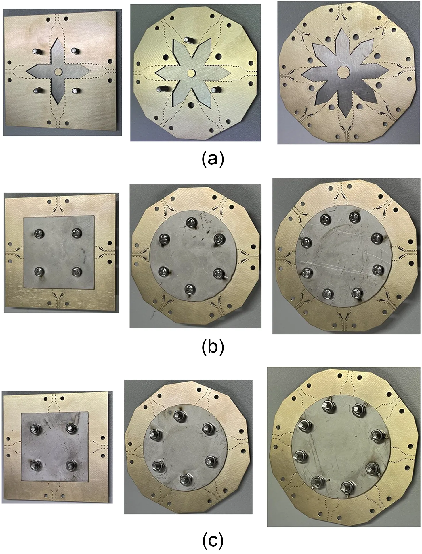
Fig.8 Interior (a),top (b),and bottom (c) views of the fabricated prototypes (two-channel,three-channel,and four-channel crossovers from left to right)
To describe the experimental results more clearly,an analysis based on the simulated and measured results of the crossovers is given in Section 3 of the supplementary materials for a detailed description.It can be concluded that the largest difference between the simulation and the measurement is in the insertion loss,about 1.7 dB.This discrepancy comes mainly from the insertion loss of the connectors,that of the connection between the connectors and the CPW,and the fabrication tolerance.The additional insertion loss mentioned above can be calibrated by using a thru-reflect-line (TRL) calibration to correct the effects of connectors and transitions,to correct characterize the demonstrator.The details of the calibration process are demonstrated in Doghri et al.(2015).
3.2 Discussion
The comparisons between the proposed air-filled SIW crossovers and similar designs with two or more channels are summarized in Tables 2 and 3,respectively.It is concluded that using microstrip line can build extraordinarily compact two-channel crossover (Tajik et al.,2018).However,the microstrip line as an open structure would lead to increased loss operating at higher frequencies.Considering designs in the literature (Djerafi and Wu,2009;Hesari and Bornemann,2017;Ali and Sebak,2018;Sun et al.,2020),it is noted that all of them suffer from relatively small bandwidth and large footprint when using either SIW or printed ridge gap waveguide technology.This brings the advantage of the proposed method in two-channel crossover designs;that is,the two-channel air-filled SIW crossover has a large FBW of 33% in the simulation and a reduced size of 0.74λ×0.74λ(λis the freespace wavelength at the center frequency).For fair comparisons,the FBW result is extracted from the complete model in the simulation including the SIW crossover and the transitions from air-filled SIW to CPW,and the size is related to the coupling area,which is surrounded by the open air-filled SIWs.
Table 3 describes crossovers with more than two channels.It can be seen that using a microstrip can build similar compact crossovers (Wu et al.,2014;Tang and Chuang,2015;Chu and Tang,2018).However,SIW technologies usually suffer from a larger footprint (Lian et al.,2020;Zhou and Wu,2020).The designed three-and four-channel crossovers effectively reduce the occupied areas while maintaining sufficient FBWs.
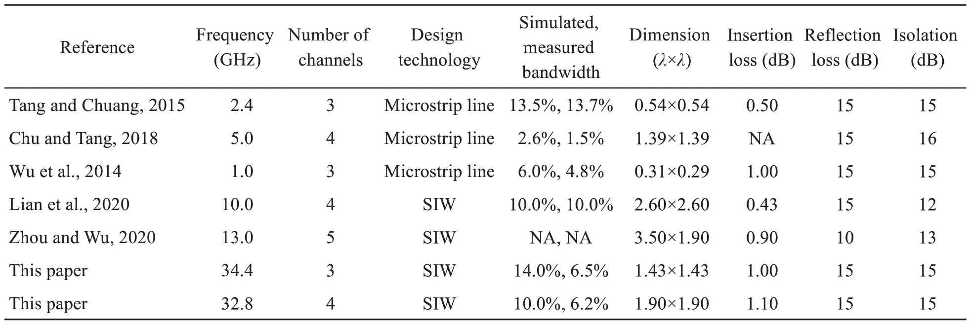
Table 3 Comparisons between the designed multi-channel crossovers and similar designs
4 Conclusions
In this work,a new method of crossover designs is presented by introducing an HCL in the middle of the air-filled SIW crossover cavity.According to raytracing analysis,the introduced HCL can concentrate and direct the electromagnetic wave in the desired direction and suppress the scattering within the cavity.Two-,three-,and four-channel air-filled SIW crossovers are designed and fabricated successively to demonstrate the feasibility of the proposed method.The corresponding FBWs of these cases in the simulation are 33%,14%,and 10%,separately.The dimensions of their core areas are only 0.74λ×0.74λ,1.43λ×1.43λ,and 1.90λ×1.90λ,separately.Compared with similar approaches,the designed crossovers show the merits of simple structure,compactness,and wide FBWs.
Contributors
Chun GENG and Jiwei LIAN designed the research.Chun GENG processed the data.Chun GENG and Jiwei LIAN drafted the paper.Dazhi DING revised and finalized the paper.
Compliance with ethics guidelines
Chun GENG,Jiwei LIAN,and Dazhi DING declare that they have no conflict of interest.
Data availability
The data that support the findings of this study are available from the corresponding author upon reasonable request.
List of supplementary materials
1 Supplement to the operation principle
2 Supplement to the design process
3 Supplement to the experiment
——上海老年大学教学大纲建设实践探索
——老年大学教学大纲实践与探索
——以《工程制图与识图》为例
 Frontiers of Information Technology & Electronic Engineering2023年9期
- Frontiers of Information Technology & Electronic Engineering的其它文章
- Matrix-valued distributed stochastic optimization with constraints∗
- Distributed optimization based on improved push-sum framework for optimization problem with multiple local constraints and its application in smart grid∗
- A home energy management approach using decoupling value and policy in reinforcement learning∗
- Exploring nonlinear spatiotemporal effects for personalized next point-of-interest recommendation
- LDformer: a parallel neural network model for long-term power forecasting*
- Mixture test strategy optimization for analog systems∗#
