Effect of variable-angle trajectory structure on mechanical performance of CF/PEEK laminates made by robotic fiber placement
Shouzheng SUN ,Hiyng MEI ,Yng WANG ,Jihi ZHANG,c ,Zhenyu HAN ,Jingln GUO
a State Key Laboratory of Robotics and System,Harbin Institute of Technology,Harbin 150001,China
b Wuhu Robot Technology Research Institute,Harbin Institute of Technology,Wuhu 241000,China
c Shanghai Spaceflight Precision Machinery Institute,Shanghai 201600,China
d School of Mechanical and Power Engineering,Harbin University of Science and Technology,Harbin 150080,China
KEYWORDS Fiber reinforced plastics;Mechanical properties;Robotic fiber placement;Thermoplastics;Trajectory design;Variable-angle laminate
Abstract In comparison to the traditional fixed-angle trajectory,the variable-angle trajectory has a greater design space.However,it is a challenge to determine which common design curve structure is the most effective for improving mechanical performance.This work explores the effects of various design curves such as fixed-angle curve,linear curve,arc curve,sine curve,Bezier curve,and cubic polynomial curve trajectories on mechanical performance of laminates,including vibration modal performance and buckling performance.Genetic algorithm and improved NSGA-II algorithm are then used to optimize various curve structures.The results are confirmed utilizing thermoplastic Carbon Fiber (CF)/Polyether-Ether-Ketone (PEEK) laminates made by robotic fiber placement experiments.The relationship model between different mechanical performance and curve design variables is established.The optimization of variable-angle structure with mechanical properties as input variables is achieved.Meanwhile,a full-process angle-variable laying software platform from trajectory planning (CAD),trajectory optimization to manufacturing (CAM) is developed for facilitating the fiber placement application.
1.Introduction
Thermosetting resin-based composite materials have been widely used in aerospace,energy,automobile industry,and other fields.1–3They are indispensable due to their lightweight and high strength features,although they do have some drawbacks,such as the inability to be recycled and reused.Thermoplastic composites provide a number of advantages over traditional thermosetting composites,including high toughness,high impact resistance,recyclability,high production efficiency (in-situconsolidation),unlimited prepreg storage periods,and ease of welding repair.It is one of the materials of choice for future aeronautical structural components.4–8Hand lay-up,molding,pultrusion,filament winding,automated tape laying,automated fiber placement,and other techniques are available for composite production.Automated Fiber Placement(AFP)technique as shown in Fig.1 appeared in the 1970s and emerged in the aerospace industry.It combines the advantages of filament winding and automated tape laying,which is one of the fastest and most effective fully automated manufacturing techniques for composite materials.9–13Robotic fiber placement refers to a placement head that is driven by a robot and has more degrees of freedom,making it ideal for the manufacturing of complicated curved surfaces and variable-angle structures.
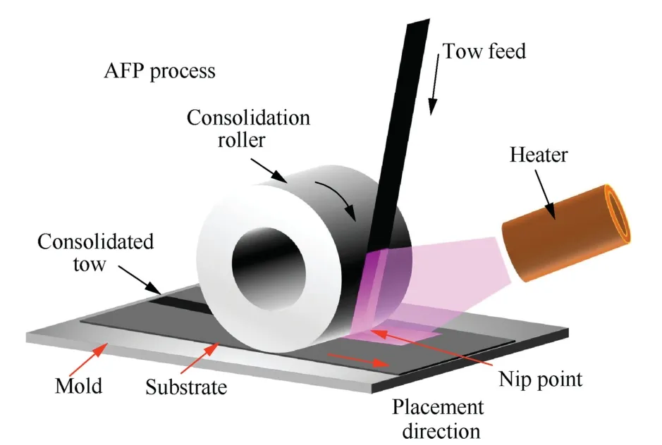
Fig.1 Automated fiber placement process.
Fibers are commonly arranged in a straight path of 0°,45°,or 90° to produce a layer in the AFP process,and then the entire structure is formed by different layers.14The straight path design is straightforward and can be used to suit a variety of engineering objectives.However,the angles of fibers in each layer are the same.The anisotropy of composite materials is not completely utilized.The design space for using traditional fixed-angle laminates to improve mechanical performance is restricted,especially for load-bearing stability or modal fundamental frequency.15,16The design process has continuously evolved from a fixed-angle trajectory to a variable-angle trajectory to improve the structural performance of composite components and match the actual needs of various projects.The AFP can flexibly manage the continuous change of fiber angle,resulting in a more advantageous stiffness distribution and,ultimately,improving the mechanical performance of laminates without adding weight.17–22Some studies have been carried out on the design of variable-angle laminates.The variable-angle path is generally implemented by the means of designing curves,in addition to the usage of the discrete method.Marouene et al.23employed an arc curve with constant curvature.The equations of the center line and the upper and lower contours were presented.Equations were used to investigate the causes of overlap and gaps.After that,compression buckling tests were carried out on laminates with complete overlaps and gaps.The results showed that the entirely overlapping laying method produced laminates with better compression buckling performance.The design variables of the laminate were cubic polynomial curve coefficients,according to Honda and Narita.24The non-dominant sorting algorithm was utilized to solve the multi-objective problem of optimizing tensile failure strength and average turning radius of the curved fiber,demonstrating that the method could produce a variable-angle structure with improved mechanical performance.Cao et al.25investigated the interlaminar performance of thermoplastic components and the heat transfer model of the thermoplastic AFP process.The effects of the connection point parameter β on the buckling load and fundamental frequency of the variable-angle laminate(Bezier curve path) were obtained through simulation.However,the initial angle and the end angle are not integrated for detailed analysis.Zhang et al.26used parametric programming to model the variable-angle skin based on the arc curve design,and then optimized the design parameters through the response surface method to increase the fundamental frequency of the solar wing plate by 31.18%.Finally,a proportional sample was made by AFP,but this optimization strategy can only be used on models with few variables.
Wang et al.27presented a novel Load-Dependent Path Planning (LPP) method to generate printing path for Carbon Fiber Reinforecd Polymers (CFRPs),which exactly follows the load transmission path of the parts and could provide higher mechanical properties.A topology optimization method is applied to simplify the original disordered load distribution.In the developed Stress Vector Tracing (SVT) algorithm,the printing paths are generated along the load transmission path with the variable spacing of adjacent paths.The LPP method has been compared with the state-of-the-art printing path planning method for continuous fibers and shown better load-bearing and printability.Esposito et al.28proposed a strain-and stress-based fiber lay-up trajectory planning method that topologically optimized the fiber trajectories induced by the loads on[0°/90°/45°/–45°]quasi-isotropic laminates.The experimental results show that the laminates laid according to the optimized trajectories have larger strain energy gains for different loads compared to the quasiisotropic laminates.Some relevant references of variableangle trajectories are shown in Table 1.23,24,27–34
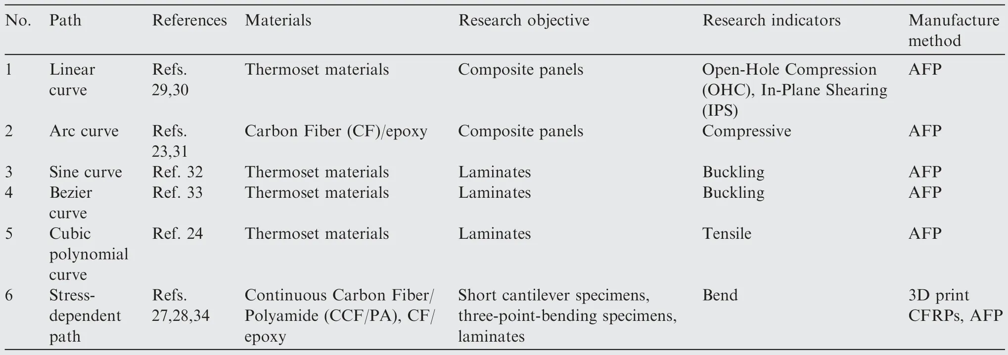
Table 1 Some relevant references of variable-angle trajectories.23,24,27–34
The stress distribution-based curved fiber design method is not limited to certain curve types and has a larger design space,while it is also able to fulfill the limits of various process conditions.The stress distribution-based curved fiber design method produces trajectories that are much complex,with multiple curves with large curvature,and the method is mostly used in continuous fiber 3D printing since the turning radius of tow is almost unlimited,such as Refs.27 and 34.Following research and analysis,the method used for lay-up molding has some issues.First,the tow has a certain width,which limits the radius of curvature,and the stress distribution trajectory is designed with a complex curve,which cannot be laid directly and must undergo a complex optimization process again,taking into account the tow’s continuity,turning radius,and especially gap/overlap defects.As indicated in Ref.28,the final obtained stress distribution of the actual plate may differ slightly from the simulation results.Because of their high toughness,thermoplastic composites have a large lay-up turning radius,which limits the design space of the stress distribution design method.Furthermore,the primary applications are satellite panels or solar wing panels,both of which demand high dynamic performance,such as the major topic—vibrationperformance.Because the fundamental frequency,which is directly connected to vibration performance,is mostly related to structural form but not much to stress,designing the curve with the stress distribution as input variables is difficult.Additionally,regular curves lose some design space but have explicit analytical formulations,are computationally efficient and ideal for engineering applications,and offer considerable advantages in optimization calculation and trajectory output.The variable-angle structure of regular curves can increase the fundamental frequency and buckling performance of laminates to some extent compared to traditional laminates.It offers a wide range of prospective applications in aerospace structural parts,but scholars have yet determined which of the numerous design curves is the most beneficial for increasing the performance of variable-angle laminates.Furthermore,the majority of variable-angle laminate research focuses on a single mechanical performance while there are limited studies on multi-mechanical performance optimization.
In response to the problems mentioned above,this work covers a wide range of common design curves and investigates the effects of various design curves on fundamental frequency and buckling performance.The rest of this paper is organized as follows.Section 2 introduces common trajectory equations.The laying method and variable-angle Finite Element (FE)models are established.In Section 3,single-objective and multi-objective optimization of vibration and buckling performance for various curves are carried out using Genetic algorithm and the improved NSGA-II method,respectively.The verification experiments using CF/Polyether-Ether-Ketone(PEEK) are then realized.Meanwhile,in Sections 4 and 5,a software is developed to integrate the complete design process for the variable-angle laminate.The final objective is to use mechanical properties as input variables and inverse design ideas to improve the variable-angle structure.
2.Variable-angle configuration based on multiple curves
2.1.Reference path
A ply of composite laminates is laid by many prepreg tows.Translation or parallels to the centerline of a tow path can be used to derive the centerline trajectory of these numerous prepreg tows.The reference path refers to the path’s centerline.The standard reference path is usually a straight line.Because the straight path cannot determine the fiber orientation in a ply,the design space for fixed-angle laminates is reduced.In contrast,the variable-angle laminates’ design space is adaptable and free,and can be used to meet the needs of a wide range of scenarios.However,most of the references focus on a variable-angle structure but ignores the overall effect of variable-angle plies with various curved structures on mechanical performance.As a result,the design reference paths are the common straight line,linear variable-angle curve,arc curve,sine curve,Bezier curve,and cubic polynomial curve.These six reference path expressions are generated.
2.1.1.Straight path
At the center of laminate,a rectangular coordinate system is constructed.Each point is on the straight line that has a fixed angle with the coordinate axis.The shape of the laminate’s reference pathFibased on the straight line (NS) can be found in Fig.2(a),and the expression is shown as

wherexis the abscissa corresponding to the fiber position,mm;θiis the straight fiber angle of thei-th layer,(°);ntis the number of laminate layers.
2.1.2.Linear curve path
Because of their simple expression and design flexibility,linear variable-angle curves (TS-L) are frequently employed in the design of variable-angle laminates,as shown in Fig.2(b).The angle between the tangent line of the curve andx-axis changes in a linear relationship with thexcoordinates.The reference path for a linear variable-angle curve can be written as35
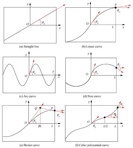
Fig.2 Reference path for different curves.

whereLis 1/2 of the length of laminate,mm;θi0is the initial angle of the reference path of thei-th ply,(°);θi1is the end angle of the reference path of thei-th ply,(°).
2.1.3.Arc curve path
As illustrated in Fig.2(c),the curvature of the arc curve(TS-A)is equal on each point.The laying process can be intuitively described by the curvature.The reference path of the arc curve can be obtained by
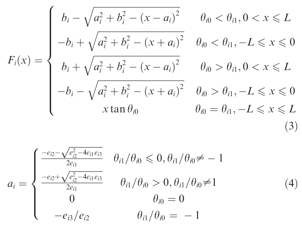
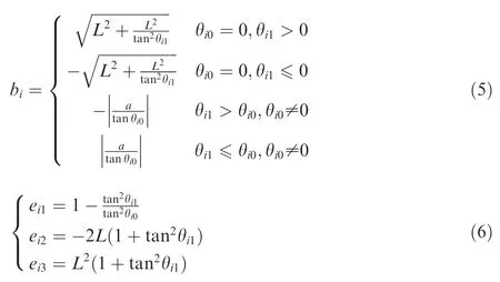
whereaiandbiis the abscissa and ordinate of the arc center,respectively.
2.1.4.Sine curve path
From Fig.2(d),the sine curve (TS-S) is a periodic function curve.The expression of the reference path of the laminate with the initial angle θi0and the periodTiis

2.1.5.Bezier curve path
The quadratic Bezier curve (TS-B) has a design flexibility,as shown in Fig.2(e).The reference path expression can be obtained by25
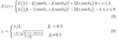
where βiis the connection point parameter and the value range is [0,1].
2.1.6.Cubic polynomial curve path
The cubic polynomial curve (TS-C) is shown in Fig.2(f).The mathematical expression of the reference path of the laminate based on the cubic polynomial curve can be obtained by

whereA,BandCare the polynomial coefficients;θipis the fiber angle corresponding to the abscissa of 1/4 laminate length,(°).
To increase the flexibility of its trajectory planning,the relative coordinate transformation equation can be utilized to generate the path in any coordinate systems for the mentioned reference path.

wherex′andy′are the transformed coordinate points;φ is the coordinate rotation angle,(°);θʹis the fiber direction after coordinate transformation,(°);θcis the fiber direction before coordinate transformation,(°).
To acquire the fiber angles at different points in the multiple design curves in the laminate modeling,equidistant straight lines are used to simulate the design curve.The curvature of the design curve must be restricted during the following optimization of the laminate structure.The curvature of the quadratic curve is used to replace the curvature of the discrete points on the design curve because the direct derivation of part of the design curve is complicated.This method can be used to calculate any curvature of the design curve.
2.2.Model
Following the determination of the reference path trajectory,a ply construction method must be determined so that the reference path extends across the entire ply.The translation technique and the parallel approach are currently the most prevalent methods expanding the reference path.When the reference path’s fiber angle changes are modest,the two approaches have similar trajectories.However,there is a significant difference when the angle change is considerable.In theory,the use of the parallel approach to build the variableangle layup does not result in overlaps or gaps.However,because the angle between the path’s tangent line and both thexandycoordinate axes changes,the design of a variable-angle structure become complicated.Additionally,the parallel approach can alter the curve’s curvature,causing fiber wrinkles and twists to occur throughout the laying process.As a result,the parallel approach is rarely employed to construct variable-angle ply.The translation approach is to translate the fiber tow defined by the fiber reference path along they-axis equidistantly so that the fiber tow covers the entire ply.As illustrated in Fig.3,the layup created by the translation approach has the same fiber angle with they-axis.When the curve angle changes dramatically,the translation method could cause noticeable defects such as overlap and gap because the fiber angle changes along thex-axis.There are two ways to deal with the defects.One option is to cut/refeed a single tow to reduce the overlap region’s area.The other is to control the translation distance in order that the tows have complete overlap and no gaps.Although cutting/refeeding a single tow can produce a relatively flat and smooth surface,the difficulty is that the computation is complicated and the fiber continuity is lost.Comparatively,the complete overlap technique trajectory planning is more convenient,and can strengthen the laminates locally at the overlap position.23
From Fig.3,its equivalent widthwein they-axis direction is
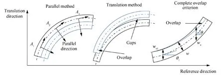
Fig.3 Variable angle laying methods.

wherewis the width of prepreg tow,mm;θ is the fiber angle,(°).
Because each position angle in thex-axis direction of the variable-angle trajectory is different,the equivalent widthwein they-axis direction is also constantly changing.Because the translation distancesis constant,there is no guarantee that there is no overlap or gap after translation.Because the complete overlap criterion is used,which ensures the smallest overlap area possible with no gaps,the tow translation distances can be calculated using

where θuis the fiber angle at different positions on the trajectory,(°).
The equivalent width of the maximum overlap area can be expressed as

To expand the designability of the reference path,a segmented curve symmetrical to the center point is adopted.For example,TS-Lrepresents a variable-angle ply obtained by translation of a two-segment linear variableangle curve with an initial angle of 30° and an end angle of 60°.The subscript ‘‘s” outside the bracket represents the symmetrical structure;the supscript‘‘r50”represents the open-hole laminates with a radius of 50 mm.The principle of balanced symmetry was followed in the design of the structure,indicating that the ply structure is symmetric to the neutral plane.Symmetrical layup can reduce the warping deformation of laminates caused by the coupling factors of tension,bending,and shear loads.36
The expressions for the definition of variable angle laminates are shown in Table 2.The supscript ‘‘r” represents the open-hole laminate.
In variable-angle laminates,fiber orientation is a function of position,but current finite element software cannot model variable-angle laminates directly.The secondary development of Abaqus-based modeling of variable-angle laminates is mainly done by python scripts,Fortran subroutines and INP files.We use Python language for secondary development of Abaqus,which has the advantages of simplicity,flexibility and expandability.The variable-angle laminate is defined as illustrated in Figs.4(a) and(b),where the laminate is first discretized into small enough areas,and the fiber angle is defined in each area,and finally the entire variable-angle laminate is obtained using the concept of ‘‘straight instead of curved”.The fiber angles along they-axis are equal everywhere because the reference path is translated along they-axis to acquire the whole ply.The discrete area is simplified in order to increase the modeling efficiency of the variable-angle laminate,as shown in Fig.4(b).For different curve design variables,the finite element modeling technique is the same.The difference is that the fiber angles of the corresponding positions inside each area are not consistent.
A secondary development of Abaqus/Python is performed as shown in Fig.4(c) to encapsulate the variable-angle laminate analysis method into a script module for later development of the variable-angle laminate design platform.To complete the variable-angle laminate model,the 3D shell parts of corresponding dimensions are created first,then the plate is divided into sufficiently fine areas according to the discrete dimensions,and finally the variable-angle laminate is created based on the material properties and calculated fiber angles.An automatic pre-and post-processing program is built to finish the automatic optimization of the variable-angle laminate,which involves creating boundary conditions,setting analysis stages,submitting computations,and extracting Open Data Base (ODB) findings,etc.
The finite element model of the variable-angle laminate is closer to the actual structure when the area and mesh are divided more densely;therefore,mesh density must be determined to increase the accuracy of finite element calculations.The mesh size is adjusted to the same size as the material variable-angle region division,and the first-order bulking load of NS-L [±〈30/60〉/±is utilized as an example to prove mesh independence.As shown in Fig.4(d),the accuracy of the analysis results increases with the increase of the mesh number,and the analysis results are much accurate when the mesh number reaches 100 × 100.After that,the difference of the analysis results is small when the mesh number continues to increase,but the calculation time increases significantly.Therefore,the subsequent analyses use the mesh number of 100 × 100.Also,the mesh convergence is better in this mesh number.
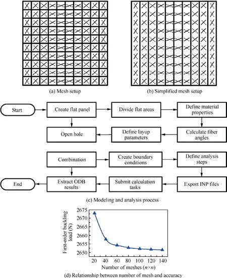
Fig.4 Method of creating FE models.
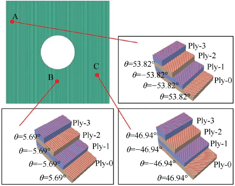
Fig.5 FE model of variable-angle laminate.
Table 337shows CF/PEEK material properties parameters used.

Table 2 Expressions of laminates.

Table 3 Material properties of CF/PEEK.37
3.Structure optimization
Composite laminates are a common structure in spacecraft.A high fundamental frequency is usually required to avoid structural damage induced by resonance in the working condition.Meanwhile,because the laminate is often subjected to com-pression or other in-plane loads,it is necessary to check the load-bearing stability to increase its critical buckling load as much as possible.The performance of composite laminates is mostly determined by the fiber angle for the same material and size.The variable-angle laminate modeling method described in Section 2 is used.The design parameters of the reference path are used as design variables.Also,the firstorder buckling load and the fundamental frequency of the vibration mode are used as the optimization objectives to investigate the designability of the open-hole structure and unopen-hole laminates.
Traditional variable-angle laminate design uses the trialand-error method,which involves selecting a single curve path and then continuously calculating and modifying the curve’s parameters to get the desired mechanical performance.The shortcoming is that this method is not conducive to the work of engineering designers.They have no way of knowing which curve is the best.It is not possible to further optimize variable angle structures using mechanical properties as input variables.Therefore,we use a multi-objective optimization method to comprehensively compare the effects of various curve paths on mechanical performance.The best mechanical performance under various curves ply is obtained,including vibration and buckling performance.Thus,this works can further help designers to improve their work efficiency.
3.1.Optimization method
Flexible buckling and vibration modal performance can be achieved with variable-angle laminates.16,38In general,no laminate structure can achieve optimal results for all objectives at the same time.Improved buckling performance,for example,may come at the tradeoff of the reduced vibration mode features or increased fiber path curvature.So,it is necessary to balance the relationship between the mechanical performance and the curvature of the reference path.Therefore,buckling performance,vibration characteristics,and curve fiber curvature are optimized.At present,the common method is to multiply each objective function by the weight and add them to generate a new single-objective problem,while the Pareto method can intuitively analyze the correlation among the objective functions in the solution through the Pareto front using the NSGA-II algorithm.
If there is a Xasuch thatfk(Xa)≤fk(Xb)for anyk,wherefkis the optimization domain,then Xbis known as the dominant solution.Whenfk(Xa)≤fk(X),where X is the design variables of the laminate,Xais called the Pareto optimal solution.The Pareto front is the set of all Pareto optimal solutions.

where D is path variable definition domain;F(X) is multiobjective optimization domain;gi(X) is evolutionary algebra.
The NSGA-II algorithm is implemented as shown in Fig.6.First,a certain scale of laminate design variables is randomly generated under the initial curvature constraint,then the mechanical properties and curvature of the initial generation of laminates are calculated to obtain the fitness value,and then the new generation of laminate population is generated by combining fast non-dominated sorting and congestion comparison,and this process is repeated until the convergence condition is satisfied.This scheme is used in the subsequent optimization,with the difference that the single-objective optimization employs buckling or fundamental frequency as an objective function,but the comprehensive optimization uses both.
The NSGA-II algorithm’s initial population generation and fitness calculation modules are changed.Because the curvature of the initial laminate randomly created by the design curve is typically large,it takes a large number of iterations to achieve a stable Pareto front within a small curvature range using simply the constraint conditions in the evolution process.Therefore,the optimization process can be greatly accelerated by placing individuals that meet the curvature constraints into the initial population,thus the efficiency of the optimization of the variable-angle laminate structure can also be improved.With regard to the fitness function,a penalty function associated to curvature is added to the fitness evaluation in addition to keeping the original fitness value for unchanged individuals.First,the FE analysis is utilized to determine the laminate’s first-order buckling load or fundamental frequency using the individual fitness evaluation function.If there are other process constraints,such as curvature,the curvature constraint violation is determined using the laminate variables.The fitness of the laminate is finally obtained by combining the FE results and the penalty value.
The average curvature κaveof the laminate is calculated in

whereNtis the number of reference points;Ndis the number of layers;rijis the radius of curvature at thej-th point in the reference curve of thei-th layer.
When the average curvature κaveof the laminate exceeds the constrained curvature κlimitin the multi-objective optimization process of the first-order buckling and fundamental frequency,a static penalty should be placed on the objective function value.The fitness Fit(X)after the curvature constraint is added can be expressed as

wheref(X)is multi-objective optimization domain;γ and λ are static penalty parameters.
3.2.Buckling optimization
Buckling load refers to the unstable equilibrium condition of a composite laminate when it is subjected to compression and other plane loads and deviates from its initial equilibrium position due to a specific lateral deflection.The critical buckling load must be calibrated in the laminate design since laminate buckling can cause irreversible damage such as resin cracks.The in-plane stiffness distribution of the laminate can be modified by changing the fiber orientation and increasing the buckling load.The NSGA-II algorithm is used for optimization with the purpose of enhancing the first-order buckling load,and the process is shown in Fig.6 to obtain the optimal design solution under different reference paths.When using a straight-line design for the first-order buckling load of an unopen-hole plate,the optimization problem can be expressed as
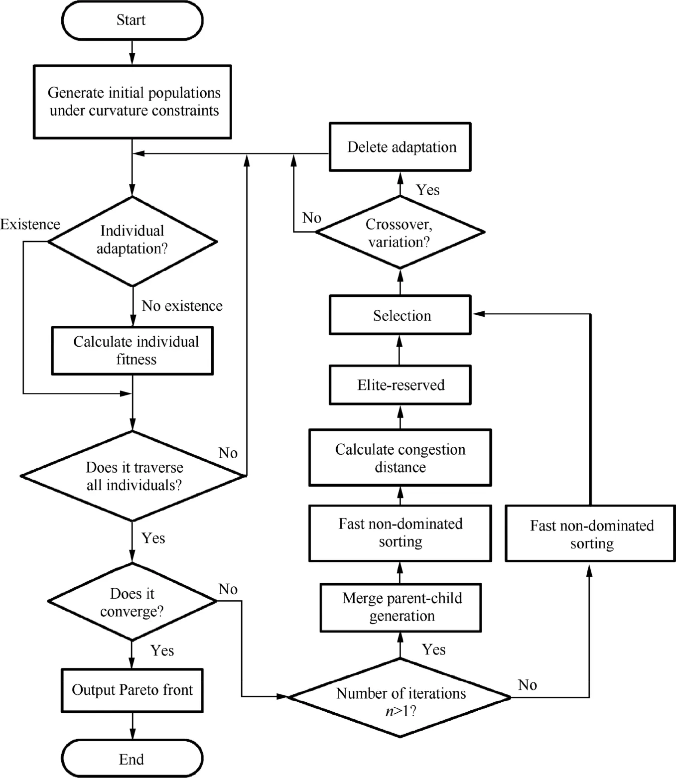
Fig.6 Optimization procedures for single objective analysis and comprehensive analysis.

where Dlis the linear path variable definition domain;fbuckleis the first-order buckling load of unopen-hole laminates.
When employing variable-angle curves to improve the buckling performance of open-hole plates,it is worth noting that too much curvature of the reference path leads to additional internal defects,hence a higher buckling load should be attained with a feasible minimum curvature.The multiobjective optimization problem of the first-order buckling load and average curvature of the laminate can be expressed as

where Dvrepresents the variable-angle path variable definition domain.
Unopen-hole laminates and open-hole laminates are both 300 mm × 300 mm in size.A circular hole with a radius of 50 mm is located in the center of the open-hole laminates.On the right side of the laminate,a uniform load of 100 N/mm is applied according to the actual working conditions.The rotation along they-andz-axes (UR2=UR3=0)and the displacement of the upper and lower edges along thez-axis(U3=0)are also constrained.Meanwhile,the laminate is constrained by the left and right displacement along thezaxis direction (U3=0) and rotation along thex-andz-axis directions (UR1=UR3=0) and restricted by the left and right rotation degrees of freedom along thex-axis direction,as shown in Figs.7(a) and (b).The material properties of CF/PEEK used are from Ref.37.A genetic algorithm and improved NSGA-II algorithm are used for single-objective optimization (straight line) and multi-objective optimization(curve),respectively.
The population tends to be stable around the 15th generation for the optimization of the buckling load of the straightline unopen-hole laminate,and the maximum buckling loadFmaxreaches 3344.7 N.The buckling load optimization of the variable-angle unopen-hole laminate is partially shown in Figs.7(e) and (f).Fig.8(a) shows the buckling load and optimal unopen-hole structure for various design paths with varying curvatures.Unopen-hole laminates built with a linear variable angle curve can achieve a higher buckling load than other paths in 1/2000-1/100 mm-1range of average curvature.The maximum buckling load of the laminate can reach 3870.6 N when the average curvature exceeds 1/300 mm-1.After that,raising of the buckling load is no longer limited by average curvature.Overall,optimizing the straight-line unopen-hole laminate can increase the buckling load by 26.27%,while optimizing the variable-angle laminate can increase the buckling load by up to 46.10%.It is demonstrated that by constructing the variable-angle trajectory in the variable-angle unopen-hole laminate,the buckling load could be improved more effectively.On the premise that the average curvature is less than 1/600 mm-1,the order of the reference paths according to the maximum buckling load value is TSL>TS-A>TS-S>TS-B>NS>TS-C.When the average curvature range is 1/400 mm-1and 1/300 mm-1,the order changes to TS-L >TS-A >TS-B >TS-S >TS-C >NS.
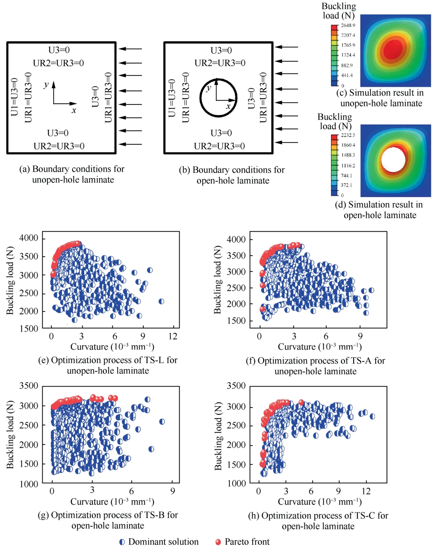
Fig.7 Optimization process of buckling load under different reference paths.
Fig.8(b)shows the maximum buckling load and the corresponding laminate structure of the open-hole laminate under different curvatures.The open-hole laminate with a linear variable angle curve has a maximum buckling load of 3247.5 N when the average curvature is 1/600 mm-1.When it comes to raising the buckling load of an open-hole laminate under different average curvatures,improving the straight path can increase the buckling load by 33.6%,while optimizing the variable angle laminate can increase the buckling load by up to 45.4%.
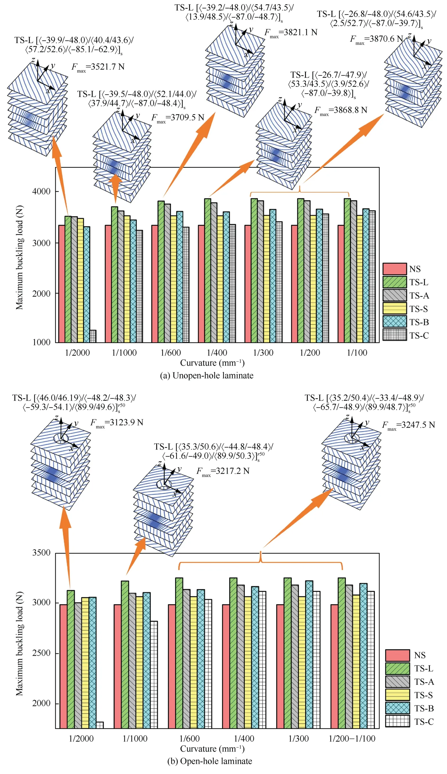
Fig.8 Optimization results of buckling load and optimal trajectory structure.
3.3.Fundamental frequency optimization
The modal analysis of the laminate can predict its vibration characteristics,and increasing its first-order modal frequency efficiently reduces resonance.The modal performance of the laminate can be efficiently adjusted by setting the layup parameters of the variable-angle laminate,which is crucial for vibration suppression,improvement of dynamic loading capacity,and noise suppression.The optimization is carried out utilizing the improved NSGA-II method with the purpose of improving the first-order fundamental frequency,as illustrated in Fig.6.When utilizing a straight line to determine the modal fundamental frequency of an unopen-hole plate,the optimization issue can be described as

where ffreqis the modal fundamental frequency of unopen-hole laminate.
When using the variable-angle curve to optimize the modal fundamental frequency of the open-hole plate,it is necessary to consider that the reference path curvature should not be too large,and the NSGA-II algorithm based on the variableangle laminate fundamental frequency optimization problem can be expressed as

The low-order vibration frequency and mode shape of the laminate are primarily considered in the vibration modal analysis of the laminate.The optimization process of vibration performance and results under different reference paths are shown in Figs.9 and 10.
The structural schematic and first-order vibration mode cloud diagrams of the variable-angle unopen-hole plate and the open-hole plate,respectively,are shown in Figs.9(c) and(d).The open-hole laminate and the unopen-hole laminate have the smallest displacement amplitude on all four sides and the largest displacement amplitude in the central region and around the hole according to the vibration mode cloud diagrams.The vibration sensitive region is elliptical with a 45° angle inclination.In addition,the first-order vibration of the open-hole plate is lower compared to the unopen-hole plate,while other variable-angle or fixed-angle unopen-hole plate and open-hole plate vibration forms are essentially the same.
Except for curvature of 1/1000 mm-1and 1/100 mm-1,the maximum fundamental frequencyfmaxis reached using TS-L path design for the unopen-hole laminate,as shown in Fig.10(a).The maximum fundamental frequency of structure designed through the TS-B path is 211.25 Hz,which is 19.9%higher than the NS path when the curvature is 1/100 mm-1.
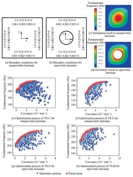
Fig.9 Optimization process of vibration performance under different reference paths.
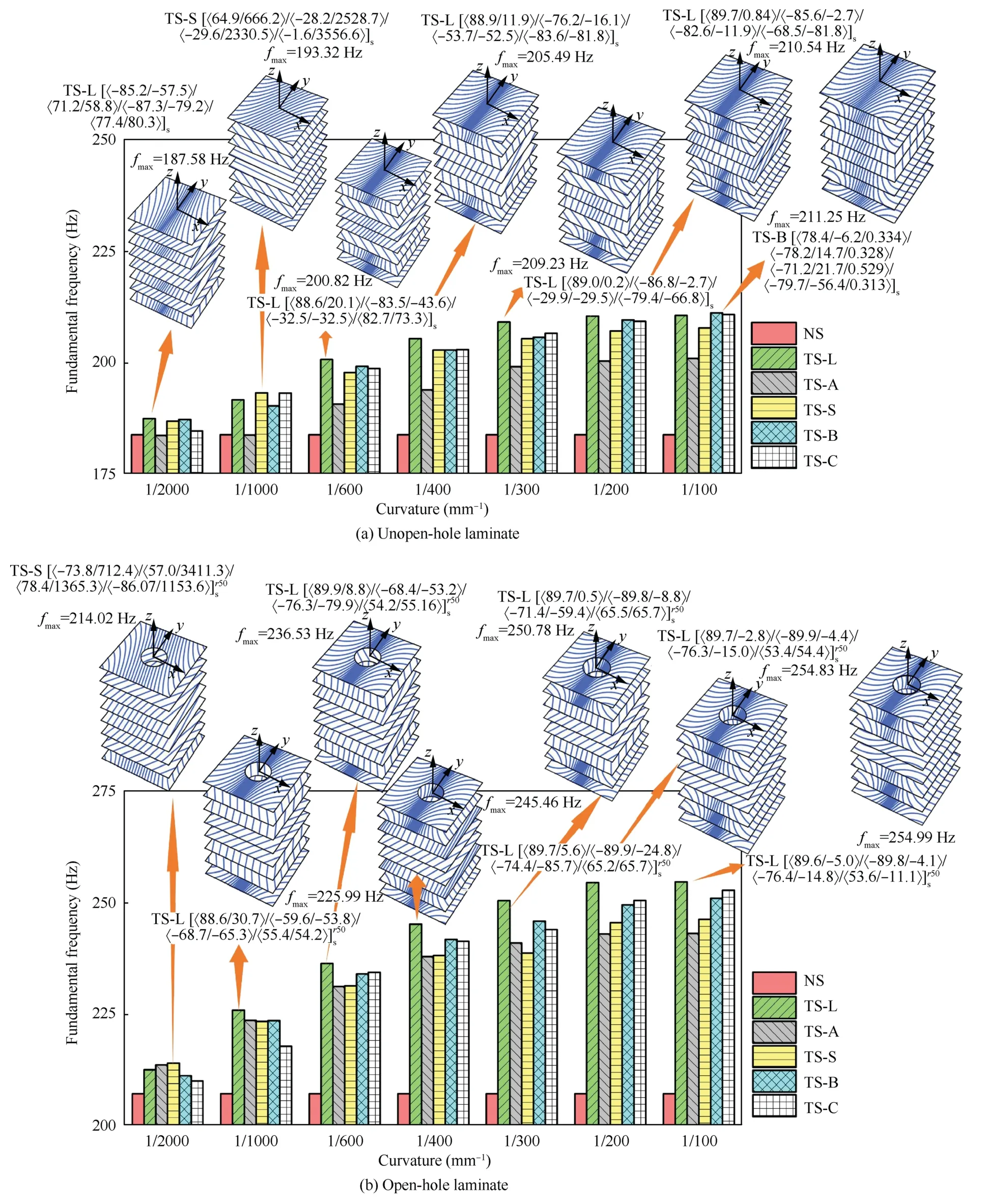
Fig.10 Optimization results of vibration performance and optimal trajectory structure.
With regard to the open-hole laminate in Fig.10(b),when the curvature is 1/100 mm-1,the maximum fundamental frequency obtained through the TS-L path is 254.99 Hz,which is 27.4% higher than that of NS.The order is TS-L >TS-C>TS-B >TS-S >TS-A >NS,when the average curvature is 1/200 mm-1and 1/100 mm-1.
3.4.Comprehensive optimization of mechanical properties
Through the single-objective analysis in Section 3.3,it can be seen that the optimal fundamental frequency range of various lay-up structures is 180–250 Hz.Based on this,we calculate the buckling load at various fundamental frequencies using the improved NSGA-II algorithm.Fig.11 shows the multiobjective optimization processes and results of the first-order frequency and buckling load of the unopen-hole laminate.When comparing different design curves,the TS-L curve produces the best results while the straight line produces the worst.The maximum buckling load of the unopen-hole laminates constructed according to the various reference paths under different fundamental frequency requirements,as well as the associated lay-up structures,are shown in Figs.11(d)–(g).The results indicated that the use of a linear variable angle curve for design generally can obtain a greater buckling load when the minimum fundamental frequency is reached.
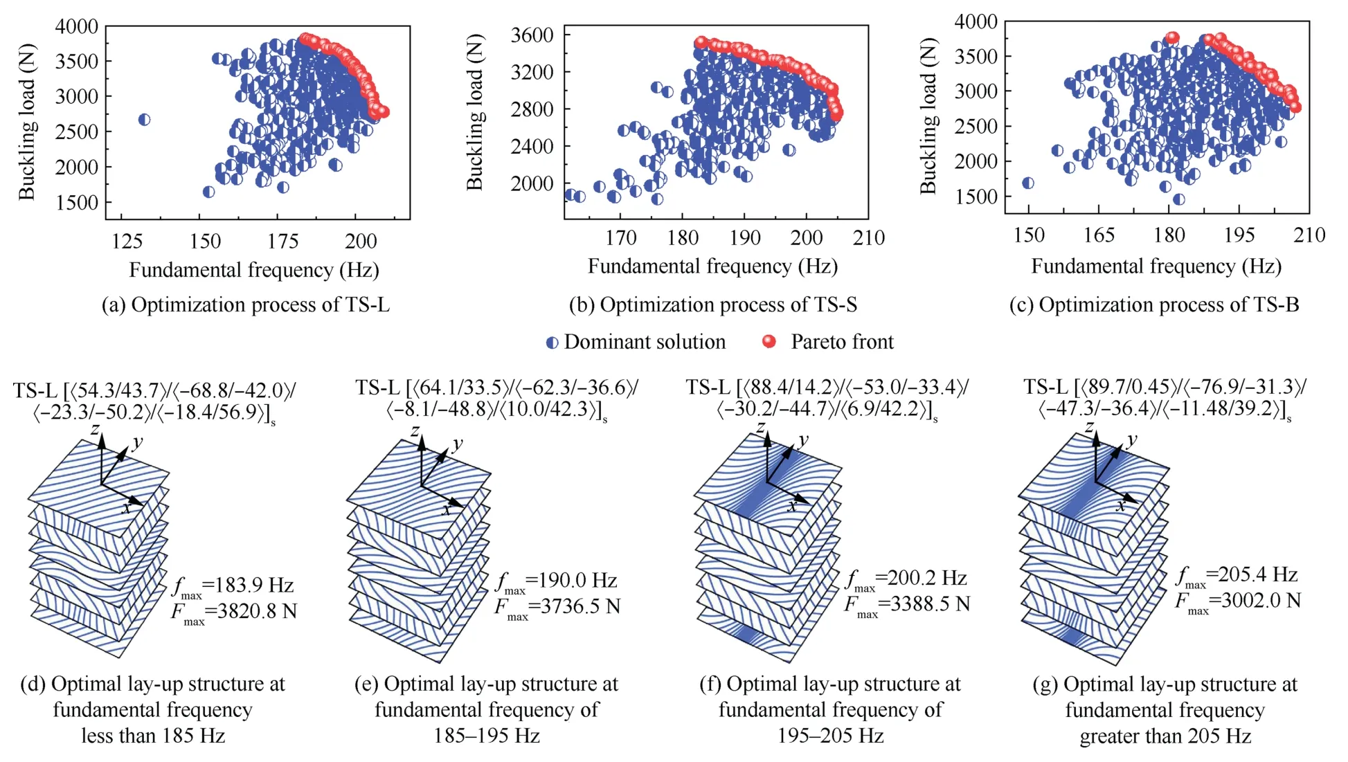
Fig.11 Multi-objective optimization process under different reference paths for unopen-hole laminate.
Fig.12 exhibits the multi-objective optimization process for open-hole laminates.The Pareto front of the fixed-angle openhole laminate is obviously inferior to the Pareto front of the variable-angle open-hole laminate.Thus,the design of the variable-angle open-hole laminate has a superior effect on the multi-objective optimization of mechanical performance.When the fundamental frequency is required to be less than 200 Hz and greater than 240 Hz,the optimal solution can be obtained based on the Bezier curve.At the fundamental frequency range of 200–230 Hz,the arc curve is a preferable choice for designing the path.When the fundamental frequency is at 230–240 Hz,the linear variable-angle path can exhibit its advantages.The optimal variable-angle structure can be selected according to actual needs.
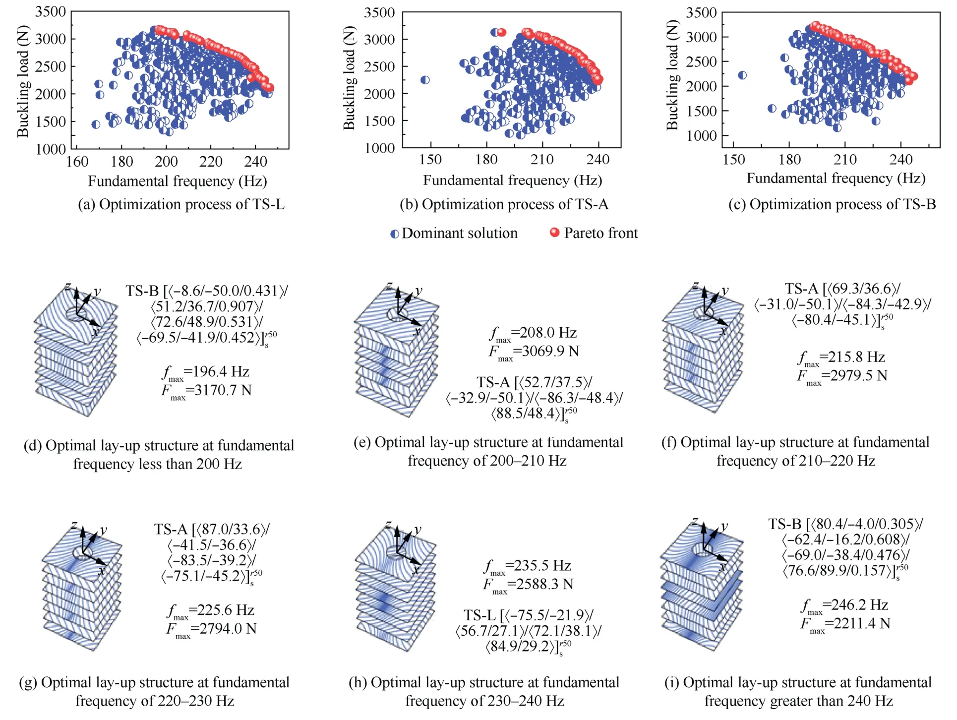
Fig.12 Multi-objective optimization process under different reference paths for open-hole laminate.
4.Experiments
To verify the accuracy of the optmization model in Section 3,experimental research is conducted.First,the uniform experiment method is first utilized to improve the process parameters,with the Interlaminar Shear Strength (ILSS) as the optimization objective.Following that,two groups of unopen-hole laminates and two groups of open-hole laminates are chosen at random for laying experiments.Finally,the vibration and buckling performance of the laminates are tested to verify the accuracy of the simulation model.
4.1.Experiment set-up
The thermoplastic composite CF/PEEK unidirectional prepreg tows used have a melting temperature of 343 °C,a glass transition temperature of 143 °C,and a width of 6.35 mm,all of which impose strict process window requirements.It is known that the bonding strength between plies has a direct influence on the final performance of the laying components,especially the variable-angle laying ones.Thus,the interlaminar shear performance can more accurately reflect laying quality.ILSS is used as a performance indicator to explore the best process window of CF/PEEK materials in terms of parameters such as heating temperature,mold temperature,laying speed,and compaction force.The uniform experiment method is a method for designing multi-factor and multi-level experiments.It requires fewer experiments than other design methods such as the orthogonal experiment and the response surface method,making it suitable for situations with a long-time frame,high cost,and multiple influencing factors.This method has been used in a variety of fields,such as biology and aerospace.39,40Therefore,the objective of the uniform experiment method is to optimize the AFP process with ILSS.The hot gas used has an outlet temperature range of 300–380 °C,the mold temperature is 130–180 °C,the compaction force is 300–900 N,and the laying speed is 10–50 mm/s.The maximum ILSS is 36.9 MPa when the laying speed is 10.9 mm/s,the compaction force is 496.7 N,the heating temperature is 380 °C,and the mold temperature is 180 °C,according to calculations(measured by universal testing machine).The laying experiments in the following experiment are carried out using these optimal process parameters.
The simulation analysis reveals that the TS-L curve has outstanding advantages in open-hole plate fundamental frequency optimization,unopen-hole plate fundamental frequency optimization,open-hole buckling optimization,unopen-hole buckling optimization and unopen-hole comprehensive optimization,so the TS-L curve is chosen as the experimental object in the experiment,and the new TS-L curve and the reference fixed-angle plate are chosen as the experimental object in order to avoid the randomness of simulation and experimental parameters.The unopen-hole laminates TS-L-1[〈77.2/25.1〉/〈–62.3/–33.2〉/〈–23.1/–50.2〉/〈0.3/45.9〉]sand NS-1[45/0/–45/90]s,and the open-hole laminates TS-L-2 [〈75.7/–25.0〉/〈52.5/33.1〉/〈83.0/32.2〉/〈84.8/47.6〉]r50sand NS-2 [45/0/–45/90]r50sare selected as experimental specimens for manufacturing.The experimental process and specimens are shown in Fig.13.
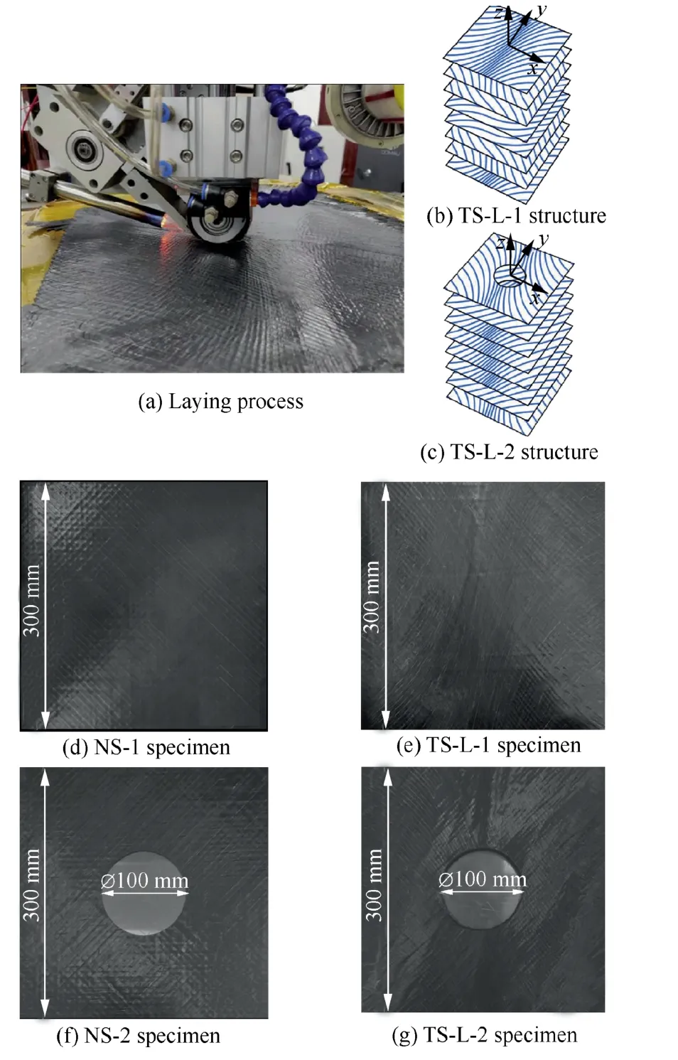
Fig.13 Experimental process and specimens.
4.2.Vibration mode test
Fig.14 shows the sensor and fixed settings used in the modal test.The excitation point is the location closest to the simulation’s maximum amplitude.Four-sided clamps secure the laminate to the vibration test bench,which matches the simulation boundary conditions.The K141-41 impact hammer is used to excite the modal response of the laminate,and the PCB 352C33 acceleration sensor,which has a sensitivity of 99.9 mV/g,is used to detect the 5 kHz vibration signals.For spectrum analysis,the DH8302 dynamic signal acquisition and analysis system is used.

Fig.14 Vibration mode test conditions.
Fig.15 demonstrates the frequency response curves of various laminates.The fundamental frequencies perpendicular to the plane are listed in Table 4 based on the laminate’s modal analysis and experiments.The experimental value of the fixed-angle laminate’s fundamental frequency is closer to the simulation,while the value of the variable-angle laminate is slightly higher.This is because the laying method is completely overlapped,resulting in some areas forming a rib-like structure that improves the structure’s rigidity and fundamental frequency.However,it can reflect the precision of simulation results to some extent.When compared to NS-1 and NS-2,the fundamental frequency of the variable-angle unopen-hole laminate TS-L-1 and the variable-angle open-hole laminate TS-L-2 increase by 22.5% and 21.3%,respectively.The theoretical optimization results of the variable-angle laminate’s fundamental frequency are largely confirmed.
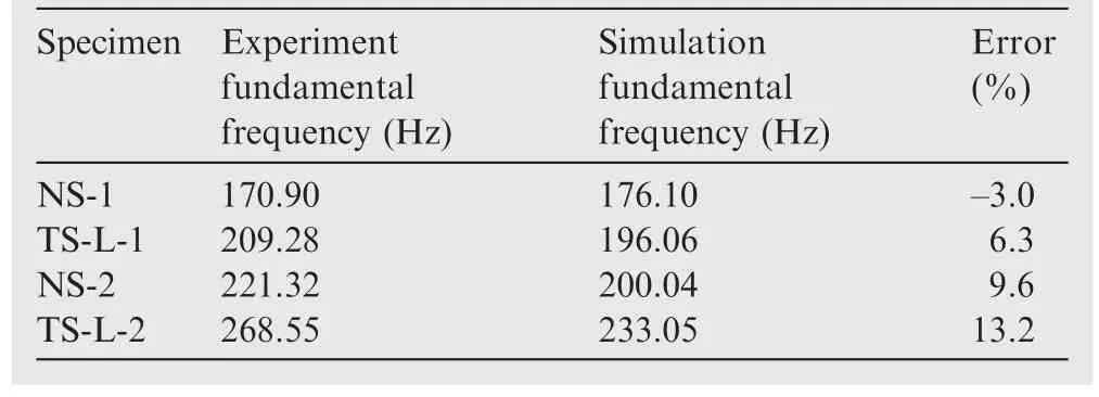
Table 4 Comparison of fundamental frequency results.
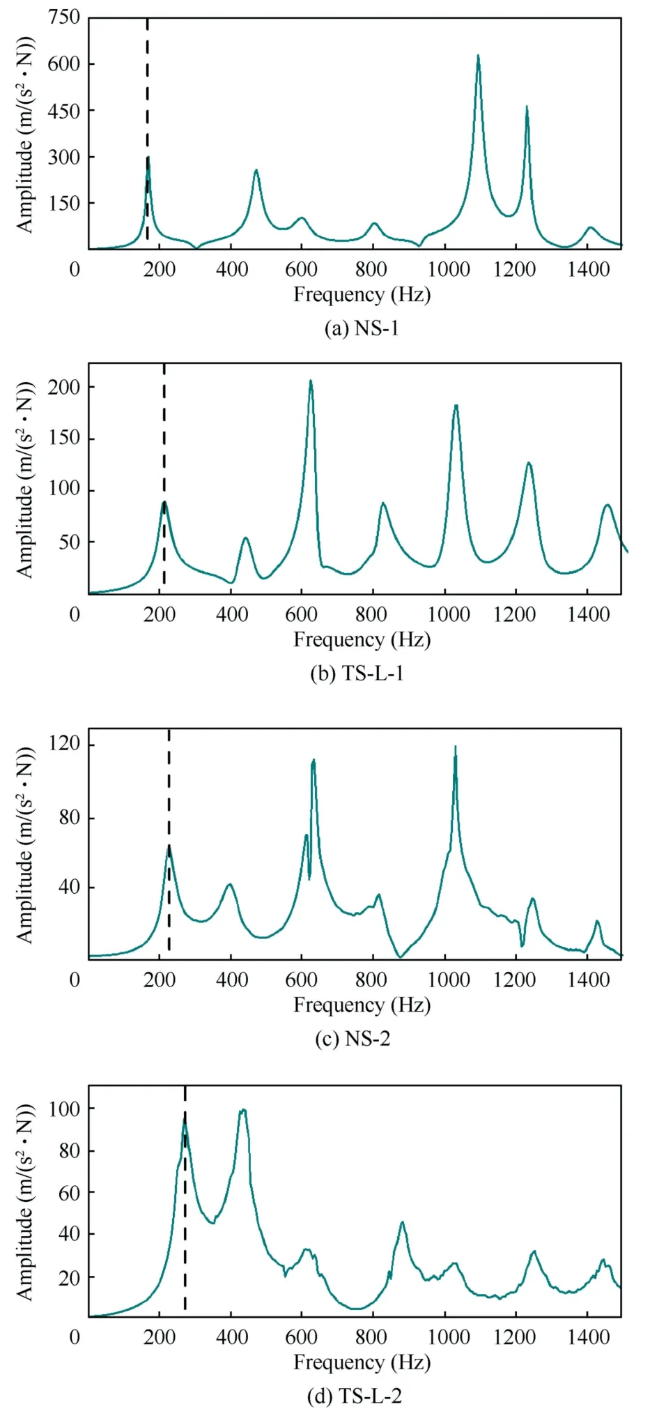
Fig.15 Frequency response curves of different specimens.
4.3.Compression buckling test
The test fixture and its principle31are used in the compression buckling experiment,as shown in Fig.16(a).The four sides of the laminate are constrained by the V-shaped gripper,which simulates the effect of four sides simply supported.Two unidirectional strain sensors are also attached along the axial direction at the specimen’s symmetry to monitor the laminate’s axial compression deformation.The ASMD5-4 resistance strain test system can obtain real-time data from the left and right strain sensors,as shown in Fig.16(b).It can be assumed that a uniform load is delivered to the upper boundary,when the data of the symmetrical location of the strain sensors is consistent.Otherwise,the compression buckling experiment needs to be re-adjusted until the laminate is uniformly loaded before proceeding.Fig.16(c) shows the MTS CNMT4202 compression testing equipment with a loading speed of 0.3 mm/min.
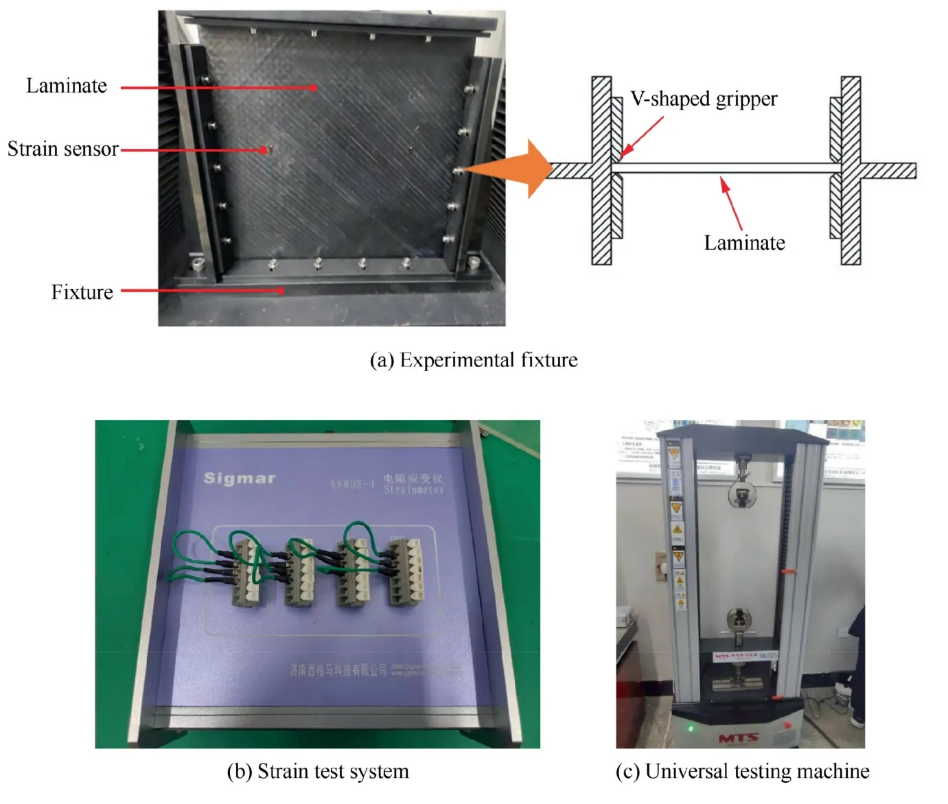
Fig.16 Buckling test experiment.
The load–displacement curves of the laminate in experiments and simulations are shown in Fig.17.The experiments show that the load–displacement response is separated into three zones to make study easier: the initial nonlinear zone(Zone-I),the pre-buckling zone (Zone-II),and the postbuckling zone (Zone-III).Zone-I occurs at the beginning of the loading process but does not reflect the real laminate performance.The range of the initial zone depends on the stability of the fixture,the defects on the side of the laminate,and the nature of the material.The pre-buckling zone is a linear elastic response zone that expresses the laminate’s compression prebuckling stiffness.After buckling,the material enters the post-buckling zone,where it continues to bear a larger stress.The critical buckling load in an ideal laminate should be easily defined from the load–displacement curve’s junction point of the pre-buckling zone and the post-buckling zone.The buckling process of a laminate’s load–displacement curve is difficult to be predicted precisely for an actual laminate.The buckling process is heavily influenced by the specimen’s geometric dimensions and whether the fixture is properly fitted.As a result,rather than a clear junction point,there is a transition zone between pre-buckling and post-buckling in the real test.Therefore,the buckling load is defined as the first corresponding point that departs from the linear pre-buckling zone.Because the simulation is carried out under idealized working conditions and the initial loading phase is very stable,the force–displacement curve obtained from the simulation does not have the initial nonlinear zone (Zone-I) compared with the experimental results.Instead,the curve enters the linear elastic response zone directly,i.e.Zone-II.Other than that,the simulation curve is closer to the experimental curve.Moreover,the buckling load obtained from the simulation is defined as the first corresponding point of deviation from the linear pre-buckling zone.
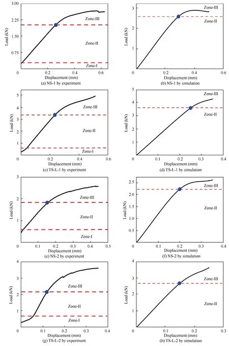
Fig.17 Load-displacement curves of different specimens.
The buckling test results in Table 5 show that the experimental buckling load is lower than that in the simulation.This is owing to the laminate’s geometric quality and incorrect clamping.Additionally,the clamping,debugging and specimen cutting process can also cause irreversible damage to the laminate,resulting in a reduction in stiffness and buckling load.Compared with NS-1 and NS-2,the buckling loads of TS-L-1 and TS-L-2 are increased by 62.2% and 18.3% respectively,confirming the theoretical model to a large extent.

Table 5 Buckling test results.
5.Applications
We integrate the modeling,analysis,optimization,and production of variable-angle composite laminates into a software platform that forms a complete design process of variableangle laminates to promote rapid application.This work develops a variable-angle laminate design optimization platform,as shown in Fig.18,to increase design and manufacturing efficiency and encourage the practical implementation of variable-angle laminates.Its main functions include variableangle laminate modeling,mechanical performance analysis,single-objective optimization of buckling load or modal fundamental frequency,multi-objective optimization of buckling load and modal fundamental frequency,variable-angle trajectory planning,and manufacturing code output.The design process of the variable-angle laminate is as follows.The mechanical characteristics of the original laminate structure are examined first.Second,the laminate is evaluated to estimate if it satisfies the design specifications.If this is not the case,the structure is optimized using the appropriate optimization method.If it is up to the specifications,the trajectory file producing the best laminate structure can be automatically exported.
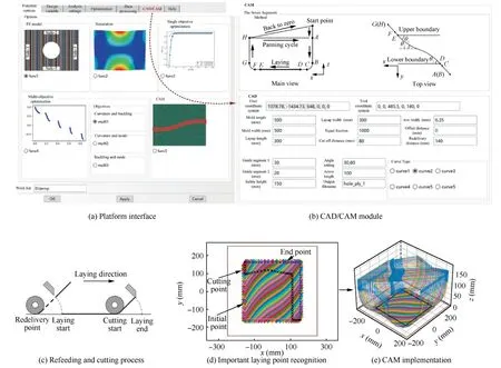
Fig.18 Variable-angle laminate design optimization platform.
The reference path design module integrates the coordinate,angle,and curvature calculation functions of six reference paths.Radio buttons and text boxes can be used to select an appropriate design curve and parameter information.By compiling functional functions,the pre-processing part defines the geometric dimensions,material properties,fiber angles,boundary settings,meshing,linear buckling,and analysis step properties of the vibration mode.The three translations and three rotations on the top,bottom,left,and right sides of the lami-nated plate can be restricted separately when defining boundary conditions.The model definition includes the number of layers,layer thickness,number of divisions,and opening radius.The post-processing part includes view adjustment,cloud image display,and data processing,which is automatically completed by the corresponding function functions.By selecting the required functions and inputting the corresponding parameters,Abaqus/CAE through the kernel program can be called to automatically model,output INP files,and deal with the analysis results.
The automatic completion of pre-and post-processing through the kernel program can not only improve the efficiency of simulation analysis and eliminate errors caused by manual operation,but can also be combined with finite element software and other optimization algorithms to improve the automation level of variable-angle laminate component optimization design.The following is the principle of calling finite element analysis using an optimization algorithm.The optimization algorithm is used to generate the initial design parameters for the variable-angle laminate,and then the results of the finite element analysis are fed back to the optimization algorithm.After a series of operations in the algorithm,new design parameters are generated.This process is repeated until the convergence condition is satisfied.
The kernel program includes a genetic algorithm and a multi-objective genetic algorithm (NSGA-II),which can optimize the variable-angle laminate’s multi-mechanical performance.Various optimization algorithm parameters,such as selection,crossover,and mutation,can be operated based on actual problems.The penalty function can also limit the curvature of the reference path.We also set aside some design and simulation interfaces that make it simple to calculate other curve trajectories and mechanical properties.
To ensure the quality of variable-angle laying process,a seven-segment layup path is adopted as shown in Fig.18(b)for variable-angle layup trajectory planning.The seven segments are rapid descent segment (AB),arc descent segment(BC),initial transition segment(CD),variable-angle layup segment(DE),end extension segment(EF),arc rise segment(FG)and rapid rise segment(GH).The aim of theABsegment is to quickly descend the consolidation roller from the safe height to PointBand match the direction of the consolidation roller with the tow’s tangent direction at PointD.TheBCsegment is to land the consolidation roller on the mold gently without collision,while the coordinates of theBCsegment are automatically calculated according to the refeeding distance and PointBis taken as the starting point of the refeeding.The major objective of placing theCDsegment ahead of theDEsection for laying is to make it easier to judge the cutting location and minimize defects produced by the descending process and the edge position’s laying distance being too short.TheDEsegment is the required laying path,which must regulate the process parameters,locate angle,and calculate the advance cutting point.TheEFsegment refers to a distance to continue laying after the end position;on the one hand,it is to ensure the laying quality at the end of the variable-angle laying segment,and on the other hand,it makes it easy to determine the processing position.To avoid the laminate damage,theFGsegment allows the laying head to be gently raised from the layup surface.TheGHsegment raises the laying head to a safe height,allowing for rapid transition to the next path.
Since there is a moving travel of the tows from the consolidation roller at the beginning of the refeeding,and there is a residual tow in the channel after the shearing action,the refeeding and shearing points in the layup trajectory need to be calculated to improve the layup quality and efficiency.Based on the above requirements,the kernel program and the interface of the CAM software are written,which are shown in Fig.18(b).The manufacturing process of variableangle laminates is more complicated than that of conventional laminates.Therefore,this software combines the sevensegment laying path to compile the CAM module shown in Figs.18(c)–(e).It can automatically generate a variable-angle laying trajectory according to the size,tow width,and reference path,and set the corresponding refeeding,cutting,clamping,pressing,and other laying actions.Meanwhile,this software can deduce the shear point according to the given advance shear distance.
6.Conclusions
The effects of variable-angle laminates with various design curve trajectories on mechanical performance,particularly vibration modal performance and buckling performance,are thoroughly investigated.Additionally,the corresponding curve parameters are optimized based on different mechanical performance requirement.Finally,the whole process design software of variable-angle laminates from trajectory design,mechanical performance optimization to manufacturing is developed for the application.Based on the presented analysis,the following conclusions can be drawn.
(1) The linear variable-angle curve outperforms other design curves in first-order buckling load optimization for unopen-hole and open-hole laminates.It is not recommended to use the cubic polynomial curve for design when the curvature is 1/2000 mm-1in the unopen-hole and the open-hole laminate.
(2) In comparison with other reference paths,the linear variable-angle curve has better designability for fundamental frequency optimization.A sine curve can be used to optimize a variable-angle unopen-hole laminate when the curvature is 1/1000 mm-1.When the curvature of an unopen-hole laminate is greater than 1/100 mm-1,the Bezier curve is more suitable.
(3) In multi-objective optimization,the use of linear variable-angle curves for unopen-hole laminates has a good design effect.Meanwhile,the linear curves,arc curves,and Bezier curves can be considered comprehensively for open-hole plates in terms of actual situation.
(4) The experimental results show that the fundamental frequency and buckling load of the variable-angle unopenhole laminate TS-L-1 increase by 22.5% and 62.2%respectively,compared with reference NS-1.The data of TS-L-2 with variable-angle open-hole laminate has increased by 21.3% and 18.3% respectively compared with NS-2,which verifies the theoretical optimization results of the variable-angle laminate structure.
The design method based on vibration deformation distribution and combined with genetic algorithm and machine learning can be proposed in the future to improve the model design method in this paper to achieve the optimal dynamic performance of the structure,because the curved fiber design method based on stress distribution can eliminate the limitation of specific curve type and has a broader design space.
Declaration of Competing Interest
The authors declare that they have no known competing financial interests or personal relationships that could have appeared to influence the work reported in this paper.
Acknowledgements
This study was co-supported by the National Natural Science Foundation of China (No.51875134),the Self-Planned Task of State Key Laboratory of Robotics and System(HIT),China(No.SKLRS202218B) and the Production and Research Project of HIT Wuhu Robot Technology Research Institute,China (No.HIT-CXY-CMP1-MWLRP-21-01).
 CHINESE JOURNAL OF AERONAUTICS2022年12期
- CHINESE JOURNAL OF AERONAUTICS的其它文章
- Control and utilization of range-dependent beampattern with waveform diverse array radars
- Airside pressure drop characteristics of three analogous serpentine tube heat exchangers considering heat transfer for aero-engine cooling
- Numerical analysis of deflection control of a gas plasma jet based on magnetohydrodynamic staggered electrode configuration
- Neural network-based model predictive control with fuzzy-SQP optimization for direct thrust control of turbofan engine
- Method for utilizing PIV to investigate high curvature and acceleration boundary layer flows around the compressor blade leading edge
- Experimental investigation of expansion effect on shock wave boundary layer interaction near a compression ramp
