Airside pressure drop characteristics of three analogous serpentine tube heat exchangers considering heat transfer for aero-engine cooling
Yinlong LIU ,Guoqiang XU,c ,Yanchn FU,d,* ,Ji WEN,d ,Shaoshuai QI ,Lulu LYU
a Research Institute of Aero-engine,Beihang University,Beijing 100083,China
b National Key Laboratory of Science and Technology on Aero-engine Aero-thermodynamics,Beihang University,Beijing 100083,China
c School of Energy and Power Engineering,Beihang University,Beijing 100083,China
d Beihang Hangzhou Innovation Institute Yuhang,Hangzhou 310023,China
e China Aerospace Aerodynamics Technology Research Institute,Beijing 100074,China
f AECC Commercial Aircraft Engine Co.,Ltd.,Shanghai 200241,China
KEYWORDS Aero-engine;Heat exchanger;Heat transfer;Pressure drop;Serpentine tube
Abstract This study explores the design,analysis,and air pressure drop assessment of three analogous air–fuel heat exchangers consisting of thin serpentine tube bundles intended for use in high Mach number aero-engines.In high speed flight,the compressor bleed air used to cool high temperature turbine blades and other hot components is too hot.Hence,aviation kerosene is applied to precool the compressor bleed air by means of novel air–fuel heat exchangers.Three light and compact heat exchangers including dozens of in-line thin serpentine tube bundles were designed and manufactured,with little difference existing in aspects of tube pitches and outer diameters among three heat exchangers.The fuel flows inside a series of parallel stainless serpentine tubes (outer diameter:2.2,1.8,1.4 mm with 0.2 mm thickness),while the air externally flows normal to tube bundles and countercurrent with fuel.Experimental studies were carried out to investigate the airside pressure drop characteristics on isothermal states with the variation of air mass flow rates and inlet temperatures.Non-isothermal measurements have also been performed to research the effect of heat transfer on pressure drops.The experimental results show that inlet temperatures have significant influence on pressure drops,and higher temperatures lead to higher pressure drops at the same mass flow rate.The hydraulic resistance coefficient decreases quickly with Reynolds number,and the descent rate slows down when Re>6000 for all three heat exchangers.Additionally,the pressure drop on heat transfer states is less than that on isothermal states for the same average temperatures.Moreover,the pressure drop through heat exchangers is greatly affected by attack angles and transverse pitches,and an asymmetric M-shaped velocity profile is generated in the crosssection of sector channels.
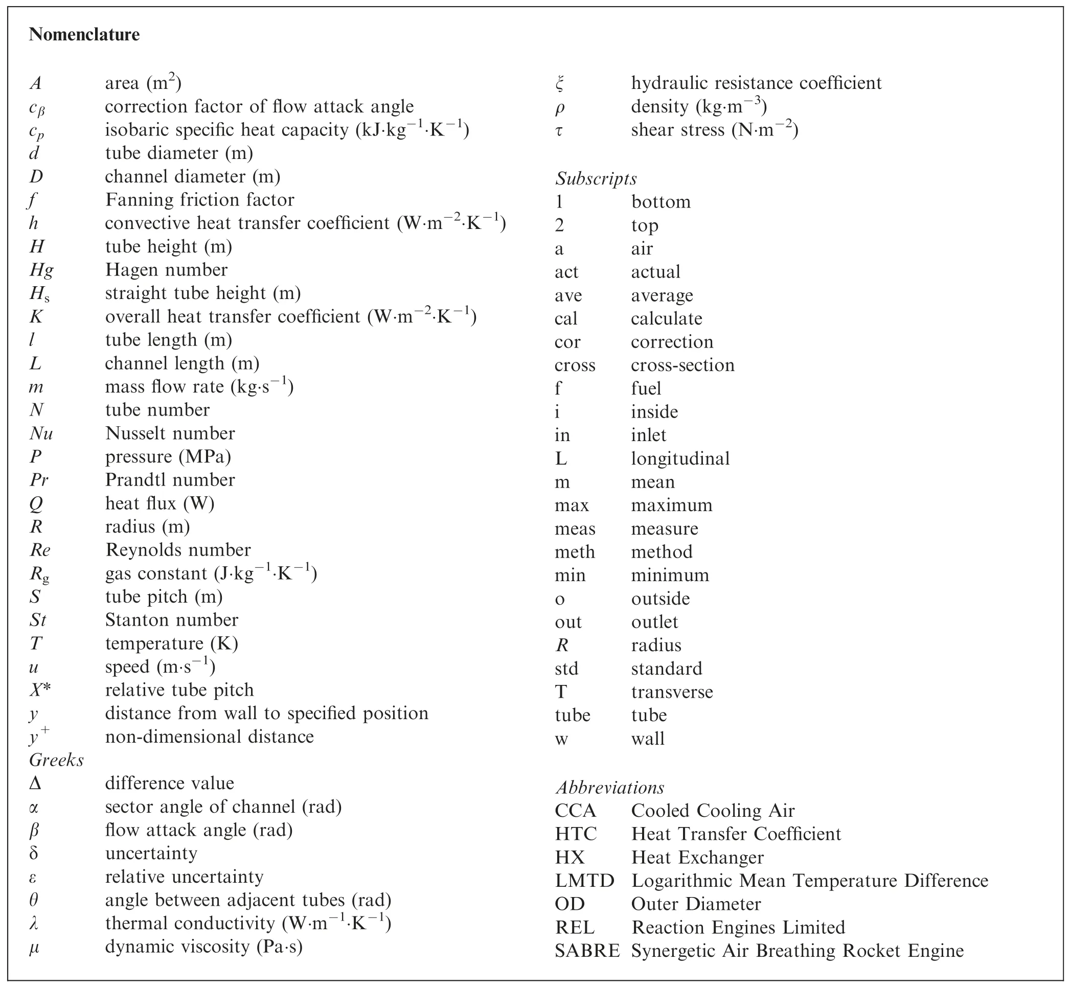
1.Introduction
The development of advanced aero-engines and hypersonic vehicles draws more and more attention due to the great scientific research value and strategic significance.Increasing turbine inlet temperatures and improving the engine compression ratio is the necessary way to enhance engine thrust and thermal efficiency.However,the turbine inlet temperatures of modern advanced turbine engines are approaching 2000 K,which greatly exceeds the permissible temperature of blade materials.Advanced sophisticated cooling technologies1,2(e.g.,convective cooling,impingement cooling,and film cooling) have been successfully applied for turbine blade cooling in the last decades,3and all such require high compressor bleed air as coolants for the pressure balance need.But,compressor bleed air is too hot to serve as coolants4due to the increasing air stagnation temperature and compressor ratio.Less amount of cooling air bled from the compressor is beneficial to engine efficiency but is detrimental to cooling performance where a large amount of cooling air is wanted.Therefore,an improvement approach on current cooling technology is urgently demanded.
Cooled Cooling Air(CCA)5,6technology is to install a Heat Exchanger (HX) on engines utilizing low temperature bypass air or onboard fuel to precool the compressor bleed air for raising its cooling quality.Since the external bypass air is extracted from the surrounding atmosphere with the advantage of no need for carrying extra coolants on board,it is often adopted as a heat sink for CCA technology.Many studies have been conducted aiming at design,manufacture,and performance verification for light and compact air-air HXs applied in aero-engines.Chepkin7introduced an air-air tubular HX applied in the Russian AL-31F engine which cooled the compressor bleed air by 150–170 K using engine external bypass air.Li et al.8and Liu et al.9have carried out experimental studies on two analogous serpentine tube bundle air-air HXs with different elbow numbers.The outside convective Heat Transfer Coefficient (HTC) was obtained by the revised Wilson method and showed disagreement with calculated data by both Zˇukauskas10and Grimison11correlations due to the relatively weaker heat transfer performance on elbow regions with respect to straight tube regions.Aristotle University of Thessaloniki and MTU Aero Engines have conducted series of experimental and numerical research on several novel airair HXs consisting of U-shaped elliptic profiled tube bundles served as recuperators in a recuperated aero gas turbine.12–15The turbine exhaust gas with high temperature was used to preheat the air from high pressure compressors before combustion aiming to reduce fuel consumption and recover waste heat.Experimental results indicated that high HTCs and low pressure drops were obtained with a staggered arrangement of elliptically profiled tubes.Besides,pollutant emissions were also reduced thanks to the application of the novel recuperator.
Whereas,the shortcomings of low heat capacity,low density,and low HTC for air compared with aviation fuel limit the application of air-air HXs on engines.Therefore,onboard aviation fuel is regarded as a better coolant for cooling hot air with fewer coolants in a compact and light air–fuel HX.Moreover,the subsequent heated fuel with a higher initial temperature at supercritical pressure can be atomized better5for following efficient combustion,resulting in a higher engine thermal efficiency.Nacke et al.16proposed a cross-flow micro-channel air–fuel HX module applied in high Mach number aircraft gas turbine engines and a large number of miniature modules could be closely spaced in annular to make an integrated HX.The cold fuel flowed through a series of parallel microchannels with a width of 0.254 mm and height of 0.762 mm,while the hot air flowed externally past rows of short and straight fins perpendicular to the fuel flow direction.Experimental results indicated that the developed theoretical model was reliable to predict fluid exit temperatures and heat transfer rates.A compact plate finned tube air–fuel HX for CCA technology was proposed by Wen et al.,17and the welding procedure between serpentine tube bundles and large flat fin rows was detailed introduced.Correction factors for flow resistance calculation on both sides were obtained based on the similar tendency between literature correlations and experimental data on isothermal tests.Employing the Gnielinski correlation18to predict heat transfer performance on tube inside,the outside convective HTC was separated from experimental data and a new empirical correlation was put forward.The Reaction Engines Limited(REL)company has invented a micro tube bundle air-helium HX for precooling high temperature intake air used for the Synergetic Air Breathing Rocket Engine (SABRE)19–23with helium serving as an intermediate medium between air and onboard propellant hydrogen.Series of tests have been carried out and great heat exchange performance was verified.24
Furthermore,the outside air pressure drop characteristics of air–liquid and air-air HXs have been paid much attention owing to the pressure demand of subsequent aerodynamic components on aero-engines.Researchers have carried out many experimental and numerical studies on tube bundle HXs to understand the influencing mechanism of several key parameters (such as tube pitch,tube row number,flow velocity,attack angle,etc.) on air pressure drop and developed applicable empirical correlations for various flow circumstances and structures.
The airside pressure drop performances of single tube25and tube banks10in crossflow have been detailed researched by Zˇukauskas in terms of fluid types,physical property,viscosity,free-stream turbulence,blockage factors,and two linear analytic diagrams were obtained to calculate pressure drops for in-line and staggered tube bundles in crossflow respectively.Kays and London26have conducted and summarized a great deal of heat transfer and flow resistance experimental data for air flowing normally to tube banks with various tube pitches and an outer diameter of 9.525 mm.For each layout,the heat transfer data were summarized asStPr2/3and flow resistance data were summarized as friction factorf.The interpolation method could be used to calculate HTC and pressure loss when a new tube pitch arrangement is introduced.Gu et al.27,28have conducted numerical studies on airside thermal–hydraulic characteristics of plain tube bundle HXs with tube outer diameter of 3 mm intended for aero-engine cooling techniques considering variable air properties.Calculated data indicated that the largest pressure drop occurred at the first tube row while the last tube row yielded the smallest pressure drop.Besides,ignorance of air property variation gave rise to the overestimation of pressure loss,and the decrease of air velocities augmented the prediction deviation.Correction factor with the form of(μw/μave)nis proposed for considering the effect of air property variability on friction factor.An HX with 0.38 mm diameter tube banks and compactness of 3000 m2/m3has been manufactured and tested by Murray et al.29to predict and verify the flow and heat transfer performance of the airhelium precooler in the SABRE.19Experimental results revealed that heat exchange capacities were close to 2 GW/m3with temperature drops up to 500 K,which were well predicted by Kays and London26Stanton correlation for external flow and Taylor30correlation for internal flow.The external pressure drop remained predictable in the isothermal flow test,but showed some excess against predicted results by Kays and London26friction factor correlations in large temperature difference situations.The reason might be attributed to the large property variation over short distances caused by bulk-tosurface temperature gradients and the two-dimensional nonuniform temperature distribution brought about by the crossflow mechanism.
Among all studies of compact tube bundle HXs,the majority of investigations focused on heat transfer,but the airside pressure drop characteristics were relatively less discussed.Besides,the influence of heat transfer and miniature tube diameters were less considered when pressure drop was investigated.Based on the application demand and previous research on air–fuel HXs in aero-engines,this paper presents three analogous compact tube bank air–fuel HXs for CCA technology applications,and serpentine tubes with the external diameter of 2.2,1.8,and 1.4 mm were chosen as basic heat transfer elements.Pressure drop tests on isothermal and nonisothermal states have been conducted,and the effect of heat transfer and attack angle on hydraulic resistances are detailed discussed.
2.Design and manufacture
2.1.Thermodynamic design
It is well known that there are plenty of HX configurations,and the optimal corresponding relation of HX types versus application environments is still debatable.For the highpressure demand on the fuel side,the tube bundle type of HX was selected in this study.As the low heat transfer temperature difference and little variation in the thermophysical property on both sides,the Logarithmic Mean Temperature Difference (LMTD) method31was used in the design and verification process of serpentine tube air–fuel HXs.In a design condition with given mass flow rates,inlet pressures,and inlet temperatures on both sides,the heat balance equation is applied to calculate one side outlet temperature in case that the other side outlet temperature is demanded in advance as follows:

where subscript ‘‘a”,‘‘f”,‘‘in”,and ‘‘out” stands for air,fuel,inlet,and outlet,respectively.The temperature difference between two fluids can be computed easily by the LMTD method for the simple co-current flow and countercurrent flow.In this paper,the air crossflows through the serpentine tube bundles locally,but the temperature difference is still calculated by the LMTD method because the elbow number in each tube exceeds four.32The LMTD formula for the overall heat transfer process is expressed as.

where ΔTmis the mean temperature difference.For circular tubes as the basic element,the overall HTC based on the outside tube area can be calculated using the one-dimensional thermal resistance equation

where subscript ‘‘i”,‘‘w”,and ‘‘o” stands for inside,wall,and outside,respectively.The Gnielinski empirical correlation18was employed to calculate the fuel side convective HTChfsince the thermophysical property of hydrocarbon fuel RP-3 varies relatively slow as the fuel operating temperature is much less than the pseudo-critical temperature.On the airside,theukauskas correlation10was chosen to predict the convective HTChawith the attack angle correction factor applied on elbow sections.The computation of heat transfer rate based on the LMTD method is defined as

The tube outside heat transfer area can be obtained by solving Eqs.(1)-(4)in order.Meanwhile,the tube length and structure of the HX are determined.

whereNis the total tube number.Pressure drops on the air and fuel side are evaluated by Eqs.(6) and (7) as follows.

where ξ andfare the hydraulic resistance coefficients on the air and fuel side respectively,andNLis the tube row number in the air flow direction.The optimization of HX structures is essential in case that the pressure loss,weight,or space occupation have a discrepancy with technical requirements.
2.2.Thermodynamic verification
Fig.1 presents the verification process,in which the outlet temperatures on both sides and thermal-dynamic performance of the HX are intended to be obtained based on the fixed structure and given inlet mass flow rates and temperatures on both sides.
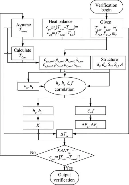
Fig.1 Flow diagram of HX verification process.
First,Ta,outis assumed with an initial value to calculateTf,outthrough the heat balance equation Eq.(1).Then,thermal properties on both sides are obtained respectively with average temperatures as reference temperatures,and HTCs and resistance coefficients on both sides are computed using suggested empirical correlations.Subsequently,the overall HTCKoand mean temperature difference ΔTmis derived by the onedimensional thermal resistance equation and LMTD method,respectively.The verification process would finish if the heat exchange capacity computed by Eq.(4) equals that by Eq.(1).Otherwise,a new value ofTa,outshould be assumed and the above-mentioned procedures continued.
2.3.Structural design
In this work,the installation space of HXs was restricted to an annular channel and six identical HX units were equally distributed annularly,meaning that each unit occupies a 60°angle sector channel as shown in Fig.2.A 60° angle sector channel was divided into a 51.9° channel for HX core installation and an 8.1° channel for braced structures and manifolds.To enhance heat transfer inside the tube by adding heat transfer area and reducing the tube number,the serpentine round tube bundles (1Cr18Ni9Ti) were chosen as primary heat transfer elements.Dozens of serpentine tubes are placed to be circumferentially uniform,with the radial and axial direction of the annular channel serving as the height and length direction of serpentine tubes,respectively.The hot air flows axially normal to serpentine tube bundles,while the hydrocarbon fuel RP-3 as coolant is injected into the serpentine tube and flows countercurrent with air as displayed in Fig.3.
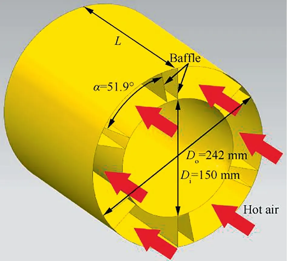
Fig.2 Installation channel diagram for HXs.
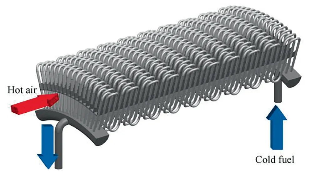
Fig.3 Three-dimensional model for 1.8 HX.
Bare round tubes with miniature external diameters of 2.2,1.8,and 1.4 mm were employed to meet the light and compact demand of HXs used in aero-engines as convective HTCs on both sides increased with the diminution of tube diameters.Meanwhile,serpentine type of tubes were employed to enhance single tube mass flow rates and heat transfer performance on the fuel side by improving space utilization and reducing the tube number.In addition,two serpentine tubes were parallelly positioned in the same row to reduce the longitudinal tube pitch to half of the elbow diameter,with the elbow section of these two serpentine tubes bent in opposite directions at a little certain angle as shown in Fig.4.
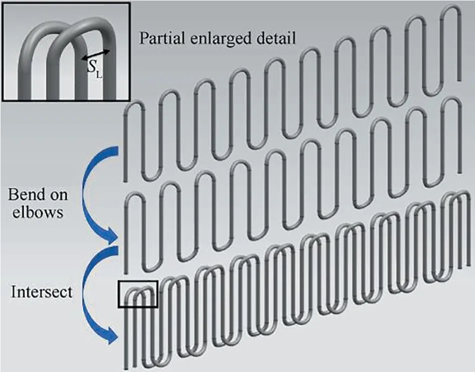
Fig.4 Sketch of assembling process for two serpentine tubes.
Fig.5 presents the detailed cross-section dimensions of 1.8 HX.Sixteen serpentine tubes were placed to be circumferentially uniform with 2.56° of the angle between adjacent tubes,resulting in the phenomenon that the tube transverse pitch varies from 4 mm to 5.34 mm along the radial direction.
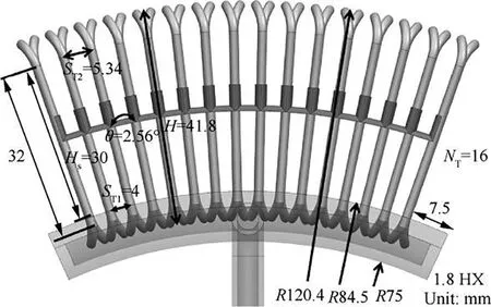
Fig.5 Diagram of cross-section dimensions for 1.8 HX.
In the manufacturing process,all tested straight round tubes on high pressure were bent to serpentine shape accompanying with elbow sections bent in the transverse direction at a little certain angle.Total tubes were then arrayed in wellplanned order,and support chips with a thickness of 0.2 mm were placed in tube transverse intervals to enhance structural strength.Subsequently,tube inlets and outlets were inserted into arc-shape manifolds,and liquid brazing solders were smeared to all contacting faces including manifolds vs.tubes and support chips vs.tubes.Later,the whole components were sent into a high temperature vacuum brazing furnace to be brazed at the environment temperature of 1070°C and vacuum degree of 0.01 Pa.Through the whole process,serpentine tube air–fuel HXs were manufactured.3D printing technology was applied in the manufacture of arc shape manifolds,and the wire cutting photo presented in Fig.6 shows that no significant burrs exist on the manifold internal surface.In addition,the infrared imaging technology was employed to test tube blockage and the uniformity of internal flow distributions among tubes,as displayed in Fig.7.With the above sophisticated design and layouts,these HXs were deemed to meet the requirement of lightness,compactness,and low flow resistance in the aerospace field,and the detailed physical parameters of the three HXs are listed in Table 1.
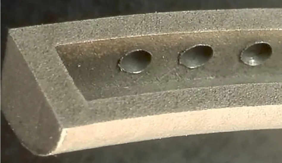
Fig.6 Wire cutting photo of 1.8 HX manifold.

Fig.7 Infrared imaging for blockage and flow uniformity detection.
3.Experimental apparatus
The thermodynamic performance experiments for air–fuel HXs were carried out on a high pressure and temperature test rig as shown in Fig.8.The experimental system includes two fluid paths,with high temperature air serving as hot fluid to simulate compressor bleed air and high pressure aviation kerosene serving as the coolant.Along the air path,the room temperature air flows from an air tank and through a filter to remove impurities.A pneumatic control valve and a thermal flow meter then stand along the air path in succession to adjust and measure the air mass flow rate.Subsequently,a tubular electric heater is used to heat air to a specified temperature,and then the heated air flows through the air–fuel HX being cooled by low temperature fuel.Before the HX,air inlet absolute pressure and temperature are measured by a pressure transducer and K type sheathed thermal couples,respectively.Five thermal couples in total are placed in the same crosssection with a well-designed layout to obtain the accurate bulk temperature by the mass flow averaging method.Later,air total pressure drops in the HX and exiting temperatures are measured,and then the cooled air is cooled further by a shell and tube type of water cooler.Last,the air is discharged into the atmosphere after flowing through an electric control valve for regulating air path operating pressures.Along the fuel path,a triple plunger pump is employed to draw fuel from a fuel tank with an overflow valve to release redundant flow.Over a gasbag damper to weaken system pressure fluctuation,the fuel flows through a Coriolis mass flowmeter and then is heated to a demanded temperature in a tube bundle preheater by a light oil burner.Behind the measurements of inlet pressures and temperatures,the fuel absorbs heat from hot air in the air–fuel HX with pressure drops and outlet temperatures being measured later.Then the hot fuel is cooled in a doublepipe water cooler and flows through a back-pressure valve for system pressure regulation.Finally,fuel flows back to the fuel tank for reuse as no coke production in the whole path.All uncertainties and ranges of airside direct measurements are listed in Table 2.
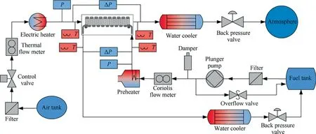
Fig.8 Schematic of experimental rig.

Table 1 Physical parameters of three HXs.

Table 2 Uncertainties and ranges of airside direct measurements.
All high temperature pipelines and test areas are covered by the thermal insulation material with thermal conductivity of 0.02 W/(m·K) (room temperature) and the type of fiber glass chopped stand mat to reduce heat loss.
4.Data reduction
4.1.Resistance coefficient definition
Airside hydraulic resistance characteristics of the above three serpentine tube HXs are focused on and investigated in this study,and air total pressure drop ΔPand non-dimensional resistance coefficient ξ are chosen as index parameters.The calculation of ξ based on experimental data is defined as.

The flow resistance for air crossflowing tube bundles includes the frictional resistance and form resistance,and the total pressure drop is adopted to represent the synthetical effect of both resistances as there is no need to divide and investigate the two resistances separately in this study.The total pressure drop is measured by a Rosemount differential pressure transducer calibrated by a standard pressure source with the range of 62.16 kPa and the relative uncertainty of ±0.065%,with the front end of pressure measuring tubes with a diameter of 3 mm being placed at the central position of gas pipelines.The characteristic velocityumaxin Eq.(8) is calculated at the minimum free flow area as follows:

The variable ρ in Eq.(9) is calculated by the ideal-gas equation,where the mean temperature and pressure of inlet and outlet are chosen as the characteristic temperature and pressure to compute thermophysical properties,respectively,as expressed in Eq.(10).

whereRgis the gas constant of air and equals 287.05 J/(kg·K).Noting that there exists a discrepancy between air actual density and calculated value by Eq.(10),which will be demonstrated in Section 4.2.Because of the in-line arrangement for tube bundles of three HXs,Aminis computed with

whereAcrossis the cross-section area of air flow channels,Atubeis the block area caused by tube bundles andNTrepresents the transverse tube number.Combining Eqs.(8)–(11),the hydraulic resistance coefficient ξ is calculated using

4.2.Uncertainty calculation
The uncertainty calculation of variables is a significant procedure for projecting experimental conditions and evaluating the reliability of result data.Based on the non-linear error propagation method,the following relative uncertainty calculation equation for resistance coefficient ξ can be deduced from Eqs.(8) and (9).

As the ideal-gas equation is used to compute air density,the density uncertainty is composed of the method uncertainty and measurement uncertainty.

Among the whole temperature and pressure conditions in this work,the maximum relative difference between calculated density using the ideal-gas equation and the true density from the National Institute of Standards and Technology (NIST)33is 0.15%for the same pressures and temperatures.The relative uncertainty of the minimum cross-section area could be unfolded as:

where μ is dynamic viscosity.Combining Eqs.(8) and (9),the calculation formula for pressure drops using hydraulic resistance coefficients is obtained as

where hydraulic resistance coefficient ξ is the function of Reynolds number,relative transverse tube pitchST/d,and relative longitudinal tube pitchSL/dfor flowing normally to bare tube bundles.10,26In addition,the airside convective HTChais defined as

where Nusselt numberNuis the function of Reynolds number,Prandtl number,relative transverse tube pitchST/d,and relative longitudinal tube pitchSL/d.10,26
Based on Eqs.(17)and(18),when HX structures,mass flow rates,and temperatures are fixed,the airside pressure drop is only determined by pressure and viscosity,and the airside convective HTC depended only on viscosity,isobaric specific heat capacity,and thermal conductivity.With thermophysical property data from the National Institute of Standards and Technology (NIST),33variations of density,isobaric specific heat capacity,thermal conductivity,and viscosity with temperatures are presented in Fig.9 at several pressures.
Fig.9 reveals that viscosity,isobaric specific heat capacity,and thermal conductivity increase with temperatures,and
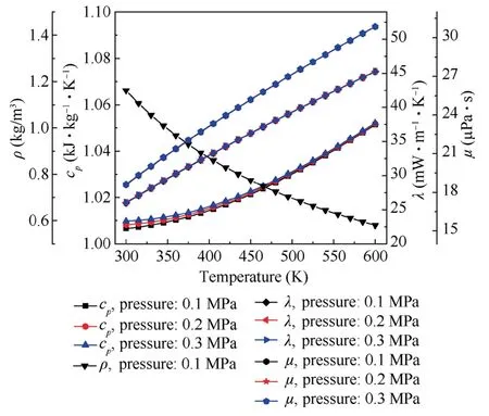
Fig.9 Variations of air thermophysical properties with temperatures at several pressures.

Combining uncertainty data of direct measurements in Table 2,the maximum relative uncertainty of resistance coefficient ξ for 2.2 HX,1.8 HX,and 1.4 HX is estimated to be 4.55%,4.74%,and 4.82% among whole experimental conditions,respectively.
4.3.Pressure drop correction
Since the air flow was supplied by a low pressure source and the air pressure drop for flowing through the water cooler was marginal due to its simple bundle arrangement,the static pressure at the HX outlet was slightly higher than atmospheric pressure under whole experimental conditions.As a result,average pressures of inlet and outlet used to determine air thermophysical properties varied frequently with pressure drops on HXs.To compare pressure drops on different conditions more visually and easily,the standard atmospheric pressure was chosen as the reference pressure under all conditions through a theoretical transformation as follows:
The Reynold number in this paper is defined as almost remain unchanged with pressures.The maximum relative deviation of thermophysical properties under different pressures for viscosity,isobaric specific heat capacity,and thermal conductivity is 0.16%,0.27%,and 0.32%,respectively.Therefore,it can be derived that air side pressure drops are only determined by operating pressures following an inversely proportional relationship and convective HTCs approximately remain unchanged when the HX structure,mass flow rate,and operating temperature are fixed.The airside actual pressure drop could be transformed to the pressure drop at the standard atmospheric pressure whether under isothermal or nonisothermal conditions.To confirm the practical feasibility of the above theoretical analyses,a test was carried out under a heat transfer state with variations of air average pressures by adjusting the back-pressure valve.
It is evidently shown in Fig.10 that airside pressure drops decrease with the augment of average operating pressures roughly following an inversely proportional relationship and air temperature drops remain almost unchanged.The average absolute value of the relative deviation between experimental pressure drops and fitted values is 1.11%.The above results validate the theoretical analysis sufficiently.Then,all experimental pressure drops in this work have been converted to pressure drops at the standard atmospheric pressure using the inversely proportional relationship between pressure drops and operating pressures with the equation expressed as
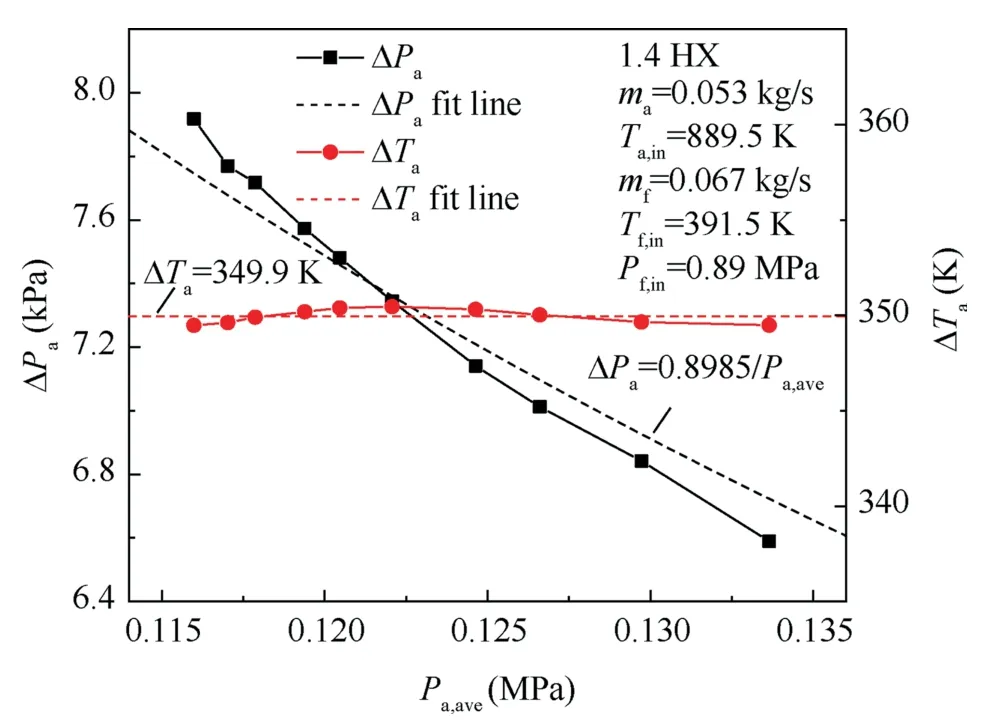
Fig.10 Variations of air side pressure drops and temperature drops with average pressures.

where ΔPcor,Pstd,ΔPact,andPavestands for the corrected pressure drop,standard atmospheric pressure,actual pressure drop,and average operating pressure.
5.Results and discussion
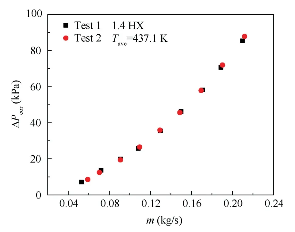
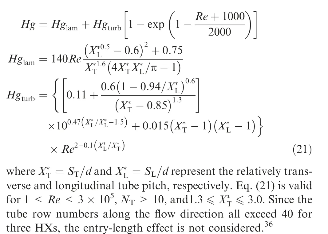
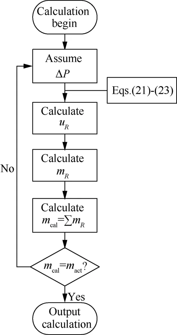
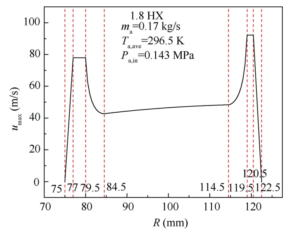
Total pressure drops through three serpentine tube bundle HXs were investigated in this work on isothermal states without heat transfer and non-isothermal states with heat transfer.On isothermal states,tests have been carried out for five different air inlet temperatures corresponding toTin=293,363,433,503,573 K (Tin=Tout),and a wide range of mass flow rates from 0.05 kg/s to 0.25 kg/s.For fluid crossflowing through tube bundles,the laminar-flow range is ofRe<200 and the turbulent-flow range ofRe>6000 with the transition-flow range within 200 The pressure drop data on heat transfer states were extracted from thermodynamic performance tests with air mass flow rates varying from 0.088 kg/s to 0.19 kg/s.Air inlet temperatures remained constantly atTin=589.5 K with outlet temperatures changing from 434 K to 470 K due to the variation of heat transfer performance.Experimental parameters are listed in Table 3. Table 3 Parameters of air pressure drop experiments. Thermal deformation and fouling deposition could be generated on HXs after a long time operation,which would havean influence on airside pressure drop characteristics.In order to verify the stability and reliability of pressure drop measurements,repetitive pressure drop experiments have been conducted before and after several high temperature thermodynamic performance tests. Fig.11 presents the corrected air pressure drop data on 1.4 HX at two different times under identical isothermal conditions withTave=437.1 K,and it is evident that the two pressure drop tendencies are almost coincident.Using the interpolation method,the maximum relative deviation is estimated to be 3.13% and the mean relative deviation 2.11%.Therefore,the tube bundle configuration was not affected by thermal deformation and fouling deposition,meaning that experimental data are repeatable. Fig.11 Repeatability verification of pressure drop measurements. Fig.12 illustrates that corrected pressure drops increase with mass flow rates,and the increasing slope generally maintains a smooth trend and exceeds the linear trend for all three HXs.Besides,pressure drops increase with air temperatures due to the simultaneously rising frictional drag and form drag,which is caused by simultaneously rising viscosity and velocity where increasing velocity is induced by decreasing temperature depended density in terms of the ideal-gas equation.Moreover,it is observed that pressure drops for 1.8 HX and 1.4 HX are roughly equal under the same condition and greater than that for 2.2 HX though the tube row number of 1.8 HX and 1.4 HX is less than that of 2.2 HX.Fig.13 reveals that the resistance coefficient ξ generally decreases withRe,and the decline rate of lowRerange is faster than that of highRerange where the dividingReis roughly located around 6000 for all three HXs.The whole trend disagrees with the linear analytic diagram of Zˇukauskas10where the friction factor decreases withReat first and generally remains constantly later with dividingRelocating around 1000 for in-line tube bundle arrangement.Moreover,it is observed from Fig.13 that the resistance coefficient ξ generally follows the decreasing trend with air temperatures,but the discrepancy of resistance coefficients under different air temperature conditions are small at lowRerange and the discrepancy amplifies at highRerange where the dividingReis also roughly located around 6000.It is deduced thatReis not enough to predict resistance coefficients and there might be another temperature depended dimensionless parameter (notReorPr) influencing pressure drops.Furthermore,the resistance coefficient of 1.8 HX and 1.4 HX is much higher than that of 2.2 HX. Fig.12 Variations of pressure drops with mass flow rates. Fig.13 Variations of resistance coefficients with Re. Since the longitudinal tube row numbersNLfor three HXs all exceed the specific row number beyond which heat transfer and hydraulic resistance for fluid crossflowing tube banks are fully developed,10the resistance coefficient ξ could represent the pressure drop characteristics for the repeatable unit of HXs.Due to the sector configuration for HXs,the transverse pitch of adjacent tubes varies from the bottom to the top,and the arithmetic mean method is employed to obtain the mean transverse pitchSTm/doas listed in Table 1.It is indicated that the relative transverse and longitudinal pitches among three HXs have only tiny differences,and all relative pitches are greater than 2.5,meaning that the tube bundle arrangement is not within the very compact range and tiny discrepancies on tube pitches just have slight effects on hydraulic resistance performance.26Besides,the micro scale effect has not taken effect as all tube outer diameters are greater than 1.0 mm.29In conclusion,these three HXs are roughly similar in the aspect of tube pitches. As Fig.14 displayed,the flow characteristic through serpentine tube HXs is the synthetic effect of crossflowing straight tube banks and flowing through series of elbow regions.The repeatable unit consists of four straight tubes and four elbows where two elbows locate in the top and other two bottom,which means that air flows through four parts of inclined tubes in the top or bottom region while air crossflows equal number of straight tubes in the middle region.It is well known that the hydraulic resistance for crossflowing normal tube banks is higher than that for incline tube banks because the form drag decreases with the reduction of flow separation caused by decreasing adverse pressure gradients and the form drag occupies a significantly larger proportion in the whole hydraulic resistance whenRe>1000.10Using data in Table 1,the ratio of elbow region area vs.the whole cross-section area for 2.2 HX,1.8 HX,and 1.4 HX is 30.4%,25%,and 20%,respectively,testifying that the resistance coefficient for 2.2 HX is lower than that for 1.8 HX and 1.4 HX. Fig.14 Schematic of single row in flow direction for 1.8 HX. Fig.15 and Fig.16 provide the comparison of airside hydraulic resistance characteristics between the isothermal state and heat transfer state.It is obvious from Fig.15 that the corrected pressure drop of 1.8 HX and 1.4 HX are higher than that of 2.2 HX on isothermal states consistently with Fig.12.However,the pressure drop on the non-isothermal state(Tave=522.6 K) is lower than that on the isothermal state(Tave=505.0 K) for all HXs while the average temperature on the non-isothermal states is higher than that on the isothermal state,which disagrees with Fig.12 tendency when no heat transfer.Besides,Fig.16 presents that the resistance coefficient on the heat transfer state(Tave=522.6 K)is less than that on both isothermal states (Tave=505.0 K andTave=575.6 K),though the resistance coefficient generally decreases with rising temperatures without heat transfer as described in Fig.13.Therefore,it is concluded that the resistance coefficient on the heat transfer state (air being cooled) is less than that on the isothermal state for the same average temperatures. Fig.15 Comparison of pressure drops between isothermal and heat transfer states. Fig.16 Comparison of resistance coefficients between isothermal and heat transfer states. When hot air outside flows through three air–fuel HXs and has a general countercurrent flow with the inside cold liquid fluid such as hydrocarbon fuel,the hot end for HXs is located in the air inlet region.And the overall heat transfer performance in the high temperature region is greater than that in the low temperature region for the following reasons. Firstly,the calculation of airside convective HTChais often advised as follows: wherea,b,andcare three empirical values withbbeing advised in the range of 0.4–0.8 andcbeing 0.36 for crossflowing in-line tube banks.10With the augment of air temperatures,the dynamic viscosity and thermal conductivity increase with roughly the same gradient while the Prandtl number just increases very little as shown in Fig.9.As a consequence,the airside convective HTC is enhanced with higher temperatures. Then,the overall heat transfer resistance between the tube outside hot air and tube inside cold fuel consists of the tube outside air heat convection resistance,tube wall thermal conduction resistance,and tube inside fuel heat convection resistance on the hypothesis of no fouling deposition.And the tube outside heat convection resistance usually accounts for the largest proportion owing to the lower density,isobaric specific heat capacity,and thermal conductivity for air compared with fuel. Based on the above two reasons,the overall heat transfer performance for the hot end is higher than that for the cold end of HXs,and the required heat transfer area of the hot end is less than that of the cold end for the same air temperature drop in terms of Eqs.(1) and (4).Hence,when hot air flows outside through HXs and has a general countercurrent flow with inside cold fuel,the heat transfer area and flow length for the temperature drop from the air inlet temperature to average temperature is less than the area and length for the temperature drop from the average temperature to outlet temperature.Drawing upon the conclusion from Fig.12 that the air pressure drop for high temperatures is higher than that for low temperatures,it could be concluded that the pressure drop for heat transfer states is lower than that for isothermal states under the same average temperatures,and using average temperatures as reference temperatures for one-dimensional pressure drop calculation would have overestimation.For pressure drop computation on heat transfer states,the piecewise calculation method should be adopted to enhance accuracy. In the design and verification progress of HXs,the onedimensional calculation method is widely applied to compute hydraulic resistance due to its convenient and efficient characteristics.Eq.(17) reveals that the tube bundle configuration has a critical influence on hydraulic resistance when air crossflowing tubular HXs,and Fig.5 presents that the transverse tube pitch and flow attack angle vary with the radius of sector channels.Zˇukauskas10has presented extensive experimental results graphically for flowing normally to inline and staggered plain tube bundles,and comprehensive pressure drop correlations for inline plain tube bundles have been recast per tube row in terms of the Hagen number by Martin35as follows: where β is the flow attack angle which equals π/2 when flow normally to tube bundles and 0 when flow parallelly to tube bundles.Based on the Martin correlation of Eq.(21)and flow attack angle relationship of Eq.(22),it is realizable to analyze the pressure drop characteristics of these three serpentine tube bundle HXs in detail with the equation as follows: According to the fluid mechanics,the pressure in each position of a cross-section could be taken as constants when fluid flows in a channel,which could be summarized as the following equation referring to Fig.14. Eq.(24) indicates that the flow speed is slower when the hydraulic resistance coefficient is higher.Then,it is easy to divide the sector channel into seven parts by channel radius in terms of hydraulic resistance characteristics and flow speeds:the near-wall region of 75 ≤R<77 andy+<200,region between near-wall region and elbows of 77 ≤R<79.5,elbow region of 79.5 ≤R<84.5,straight tube bank region of 84.5 ≤R<114.5,elbow region of 114.5 ≤R<119.5,region between the near-wall region and elbows of 119.5 ≤R<120.5,and near-wall region of 120.5 ≤R≤122.5 andy+<200.y+is a non-dimensional distance and is computed by the following equation. whereyis the distance from the stationary wall to the specified position and τwis the wall shear stress.In the estimation ofy+,the equivalent diameter and 1/7 power velocity law were used. An iterative solution algorithm is designed to compute the fluid speed on each tiny region by Eqs.(21)–(23) and the flow chart is expressed as Fig.17. Fig.17 Flow diagram of speed calculation at each location. Noting that the Martin correlation is not accurate enough when predicting hydraulic resistance for flowing normal to tube bundles,the final pressure drop in Fig.17 might not equal to the actual pressure drop,and the obtained speed distribution is just used to explain flow mechanism to some extent. Fig.18 presents the velocity profile in the sector channel of 1.8 HX,and evidently illustrates the influence of hydraulic resistance on mass flow distribution.An asymmetric M-shaped velocity profile is obtained and the velocity on lower radius regions is slower than that on higher radius regions because smaller transverse tube pitches induce larger pressure drops due to stronger interaction effects between adjacent tubes for the same speed.Therefore,in the straight tube bundle region of 84.5 ≤R<114.5,flow speed increases with radius because of the rising transverse tube pitch and uniform pressure hypothesis on the cross-section.In the elbow region of 114.5 ≤R<119.5,the flow attack angle varies from π/2 to 0,resulting in the speed increases with radius as the flow separation for flowing normally to tubes is greater than that for flowing parallel to tubes.In the region of 119.5 ≤R<120.5,uniform speed distribution is adopted due to no appropriate law or empirical correlation to represent this open region,and the speed reaches the extreme value among surrounding regions.In the near-wall region of 120.5 ≤R≤122.5 andy+<200,no-slip speed law takes effect anda linear tendency isassumed to describe the velocity decrease from the extreme value to zero.The speed distribution in lower radius regions is similar to higher,but the whole speed values are less owing to smaller transverse tube pitches.The speed distribution in Fig.18 is helpful to calculate the pressure drop and explain the hydraulic resistance characteristics of tube bundle HXs placed in sector channels.Besides,it can be easily inferred from Fig.18 that the actual averageumaxin the tube bank region is less than theumaxcalculated by Eq.(9),which means that overestimation would occur when theumaxcalculated by Eq.(9) is used to compute the pressure drop.Thus,it is important to first get the channel velocity distribution before pressure drop estimation for structures similar to this paper. Fig.18 Velocity profile of 1.8 HX in sector channel. In this work,three serpentine tube bundle HXs were manufactured,and thermodynamic experiments were conducted to investigate the pressure drop characteristics of HXs with sector sections for aero-engine CCA applications by two main parameters: inlet temperatures and mass flow rates.Isothermal tests have been carried out firstly with no heat transfer.Additionally,the effect of heat transfer on pressure drops has been studied by conducting non-isothermal measurements.The influence of mass flow rates,temperatures,heat transfer,transverse tube pitches,and attack angles on pressure drops has been discussed and the main following conclusions are obtained. (1) There is a direct correlation between pressure drops and inlet air temperatures.Higher temperatures lead to higher pressure drops for the same inlet mass flow rate. (2) Hydraulic resistance coefficients decrease with Reynolds number rapidly and then gently with dividing Reynolds number locating around 6000. (3) Pressure drops on heat transfer states are less than that on isothermal states for the same average temperatures,and one-dimensional pressure drop calculation would have overestimation with average temperatures as reference temperatures. (4) An asymmetric M-shaped velocity profile exists on the cross-section of the HX sector channel;smaller attack anglesinelbowregionslead tohighervelocitieswithrespect to larger attack angles in straight tube bundle regions. Declaration of Competing Interest The authors declare that they have no known competing financial interests or personal relationships that could have appeared to influence the work reported in this paper. Acknowledgements This study was co-supported by the National Science and Technology Major Project of China (Nos.2017-III-0005-0029,J2019-III-0021-0065,and J2019-III-0015-0059),and the National Natural Science Foundation of China (No.51906009).
5.1.Repeatability verification
5.2.Pressure drop characteristics at isothermal states


5.3.Effect of heat transfer on pressure drops


5.4.Effect of sector layouts and elbows on pressure drops


6.Conclusions
 CHINESE JOURNAL OF AERONAUTICS2022年12期
- CHINESE JOURNAL OF AERONAUTICS的其它文章
- Control and utilization of range-dependent beampattern with waveform diverse array radars
- Numerical analysis of deflection control of a gas plasma jet based on magnetohydrodynamic staggered electrode configuration
- Neural network-based model predictive control with fuzzy-SQP optimization for direct thrust control of turbofan engine
- Method for utilizing PIV to investigate high curvature and acceleration boundary layer flows around the compressor blade leading edge
- Experimental investigation of expansion effect on shock wave boundary layer interaction near a compression ramp
- Experimental study on dynamic behavior of mechanically pumped two-phase loop with a novel accumulator in simulated space environment
