Experimental study on dynamic behavior of mechanically pumped two-phase loop with a novel accumulator in simulated space environment
Qingliang MENG ,Tao ZHANG ,Feng YU ,Yu ZHAO ,Zhenming ZHAO ,Zhenhua ZHOU
a Beijing Institute of Space Mechanics and Electricity,Beijing 100094,China
b Beijing Key Laboratory of Advanced Optical Remote Sensing Technology,Beijing 100094,China
c College of Energy and Mechanical Engineering,Shanghai University of Electric Power,Shanghai 200090,China
KEYWORDS Heat and mass transfer;Mechanically pumped twophase loop (MPTL);Pressure drop fluctuation;Thermal control;Two-phase flow
Abstract Mechanically pumped two-phase loop (MPTL) which is a prominent two-phase heat transfer technology presents a promising prospect in thermal control for space payload.However,transient behavior of MPTL caused by phase-change and heat sources load-on/off in simulated space environment is rarely reported.In the present study,one MPTL setup was designed and constructed,and experimentally studied.Particularly,a novel two-phase thermally-controlled accumulator integrated with passive cooling measure and three capillary structures was designed as the temperature-control device.Dynamic behavior of the start-up,temperature control,and temperature adjustment were monitored;meanwhile,thermodynamic behavior within the proposed accumulator,the operating behavior as well as the heat and mass transfer behavior between the main loop and the accumulator were revealed.The results show that the fluid management function of the capillary structures for the novel accumulator is verified.The working point of the MPTL system can be adjusted by changing the temperature control point of the accumulator and it is little influenced by external heat flux and heat sources on/off.Pressure-drop oscillations which are manifested as fluctuations of temperature and pressure can be observed after phase changing due to the compressible volume within the accumulator and the negative-slope portion of the internal pressure.©2022 Chinese Society of Aeronautics and Astronautics.Production and hosting by Elsevier Ltd.This is an open access article under the CC BY-NC-ND license(http://creativecommons.org/licenses/by-nc-nd/4.0/).
1.Introduction
Mechanically pumped two-phase loop (MPTL) which has the superiorities in stable temperature control,long heat transfer distance,and high heat transfer capacity has been widely spread in energy and engineering applications.1Compared with the typical single-phase cooling loop,MPTL is relatively smaller and lighter since it transfers heat through the latent heat of the working fluid.Usually,the heat-transfer capability of latent heat is 2–3 times larger than that of the sensible heat.2Recently,the development of aerospace vehicles has brought about aggressive integration and miniaturization of on-board electrical and electronic devices,which will lead to exponential growth in both the overall waste heat and heat flux to be dissipated.3The features of the MPTL system promote a promising prospect in the application of spacecraft thermal control.4–7Zhang et al.8discussed the cooling principles,experimental studies,and applications of MPLTs in different fields and concluded that MPLTs are suitable as the thermal control system for future spacecrafts due to their advantages in high-accuracy temperature control and wide operating range.With the development of space technology,the operating modes and working environments are becoming more complicated and volatile;variation and stability of the temperature for the essential equipment are therefore more stringent on demand.Traditional thermal control products,like micro-grooves heat pipes or loop heat pipes,are not interested in the applications of space devices which require high temperature stability due to their limitations in heat transfer capacity and operating stability.1Xie et al.9carried out experimental investigation of the operating performance of the loop heat pipe with and without Thermoelectric Cooler (TEC) under both terrestrial gravity and acceleration fields.They pointed out that the operating performance could be improved by applying TEC.However,additional power consumption and fixing structures are needed for the TEC scheme.MPTL solves the mentioned problems related to heat pipe and loop heat pipe by employing an active pump that drives the working fluid in the loop to absorb the heat released from the heat sources (i.e.,essential devices)and then releasing the heat into the sink quickly and effectively.Spray cooling is a highly-advanced two-phase heat transfer technology besides MPTL,10and it has been widely utilized in the thermal protection of the ground-based electronic equipment.However,the aerospace-oriented spray cooling technology is still in its infancy,whose application is extremely rare due to a lack in the knowledge of flow and heat transfer behavior under microgravity.11Recently,Wang et al.proposed and tested a thermal rectifier which could ensure that heat flows in a preferential direction.12The novel thermal rectifier shows a promising prospect in antigravity thermal controller for MPTL system.Hence,MPTL is highly appreciated and urgently expected to be a promising thermal control device in space applications (such as optical payloads,large-power laser,and active antenna) due to its merits of accurate temperature control of multi-heat sources,high stability level,and long transport distance.13–16Several studies and in-orbit application cases have demonstrated the excellent preponderances of MPTL in temperature control and heat transfer for the distributed and confined payloads.The most typical MPTL case,which was developed by National Aerospace Laboratory (NLR) for thermal control of 192 silicon micro-strip detectors of Alpha Magnetic Spectrometer(AMS02) that mounted on the International Space Station(ISS),has been working for more than 9 years so far.17,18
Several experimental and theoretical investigations have been carried out to study the transient behavior of the MPTL system under different operating conditions and operating modes.Sunada et al.19derived a specific MPTL architecture based on a series of performance requirements,in which a system thermodynamic model for the performance evaluation in response to the thermal control needs of future planetary exploration was developed.Zhang et al.20carried out thermal vacuum tests in the simulated space environment to check and qualify the operating patterns of a MPTL and found that the MPTL showed excellent abilities,with respect to the various external heat flux conditions,in temperature control and self-adaption.Huang et al.21experimentally and theoretically investigated the coupling behavior between the accumulator and the main loop under the disturbed boundaries of condensers and the step change of heat loads.Liu et al.22,23investigated the start-up and dynamic operating features of the MPTL with varying heat load,mass flow rate,and temperature boundary.Meng et al.24designed and constructed a MPTL setup to reveal the transient behavior caused by the heat sources load-on/off and found oscillations in temperature and pressure in the accumulator during these processes.Van Es et al.17described the variations of in-flight sequence,commissioning results,and operating features during the hot switch between primary and secondary loop for AMS02;the results indicated that the MPTL operated flawlessly in the space.Van Es et al.18reported the test results of AMS02 about temperature stabilities of heat sources,start-up of the pump at vapor-phase,and freezing and defrosting of condensers in thermal vacuum environment;the results showed that the MPTL can fulfill all the design requirements.van Gerner et al.25,26developed a software tool to analyze the operating behavior of the MPTL which employed CO2and R134a as the working fluid;meanwhile,several methods to reduce the temperature variations in MPTL were proposed based on the software.Meng et al.27studied the mass transfer behavior between the accumulator and the main loop,and the mutual relations between the gas phase and liquid phase in the accumulator during the variation of heat loads were revealed.Liu et al.28conducted steady-state tests under different boundary conditions and unbalanced heat loads,and the results showed that MPTL operated stably and normally under these conditions.Sun et al.29observed temperature oscillations at the outlet of the evaporators when MPTL operated at low temperature and at low pump rotation speed;they pointed out that the oscillations were density wave oscillations caused by the redistribution of mass flow rate between two parallel evaporators.
However,to the authors’ best knowledge,the transient behavior of MPTL caused by phase-change and heat sources load-on/off in space environment was rarely discussed.Considering the variations and the stability requirements of the MPTLs in future in-orbit applications,it is crucial to explore the transient features of the heat and mass transfer between the accumulator and the main loop and the fluctuation characteristics of its key components.In the present study,one MPTL setup for the accurate temperature control of charged coupled devices which are commonly used in the space camera is designed and constructed.Particularly,a novel two-phase thermally-controlled accumulator integrated with passive cooling is designed to integrate with the MPTL.A thermal vacuum chamber is employed to simulate the space environment with the feature of high vacuum,ultra-low temperature,and varied external heat flux.The thermodynamic behavior of the accumulator,the operating behavior of the main loop,and the coupled heat and mass transfer process between the main loop and the accumulator are experimentally studied in detail.Meanwhile,the transient performance of the proposed accumulator is also tested and evaluated.
2.Design and construction of MPTL system for spacecraft
2.1.Operating principle of MPTL
The schematic diagram and pressure-enthalpy figure of the proposed MPTL for thermal control of spacecraft are shown in Fig.1.As shown in Fig.1(a),the MPTL consists of a pump,a two-phase thermally-controlled accumulator,a heat exchanger,a pre-heater,nine simulated heat sources and evaporators,a condenser,and the connected pipes.With the help of pressure-enthalpy diagram,the cooling cycle of the MPTL system can be analyzed by the thermodynamic state change of the working fluid.The numbers from 1 to 11 in Fig.1(b) correspond to the numbers located in Fig.1(a).The specific process is shown as follows: (A) Pressure increase process.The input electrical power is converted into the kinetic power of the working fluid through the pump and changes the state point from 1 to 2.(B) Temperature-rising process.Firstly,the state point of the working fluid drops to 3 due to the friction loss during the flowing.Then,the super-cooled fluid is pre-heated by the two-phase fluid from the evaporators,which changes the state point at the exit of the heat exchanger from 3 to 4.Finally,the pre-heated liquid then enters into the pre-heater,where it is further heated and changes to the two-phase state 5.(C) Evaporating process.The saturated fluid flows into the evaporators where it evaporates after absorbing the heat generated by the heat sources.The dryness of the fluid increases continually during this process and the state point of fluid at the exit of the last evaporator changes to 6.(D)Heat exchanging process.The state point of the working fluid also firstly drops to 7 due to the friction loss during the flowing.Then,the two-phase fluid with the state point of 7 enters into the heat exchanger where its latent heat is recycled by the super-cooled liquid.The working fluid is cooled and changes to state 8.(E) Condensing process.The state point of fluid firstly also changes to 9 due to the pressure drop of the twophase fluid during the flowing.After that,the fluid enters into the radiant condenser where it is condensed into cold fluid with a certain degree of supercooling,and the fluid state turns to 10.(F) Thermal managing process.The super-cooled liquid is evenly divided into two branches,one flows through the proposed accumulator and then converges together with the other branch.The state of fluid turns to 1 due to heat releasing in the accumulator and pressure drop.Finally,the fluid with state 1 flows into the pump.In addition,the state point of 11 is located in the accumulator;it is also the temperature control point of the system.
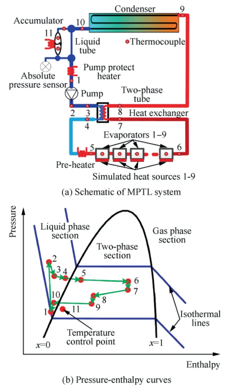
Fig.1 Schematic diagram and pressure-enthalpy curves of MPTL system.
The states of the working fluid within the accumulator and evaporators are both two-phase,so the Clausius-Clapeyron relation between them is satisfied.The temperatures inside these two components are related as.30

whereTevaandTAccuare the temperatures of fluid in evaporators and accumulator,respectively;ΔPEAis the pressure difference between the two components;(dP/dT)satis the slope of the saturation pressure–temperature line atTAccu.Eq.(1)states that the temperature within the evaporator can be managed by the accumulator.
2.2.Design and construction of novel accumulator
The accumulator,which is the key component of the MPTL system,is employed to control the saturation temperature of the evaporator and to perform fluid management of the system.The two popular design methods that have been employed to implement the control functions of the accumulator are mechanically-controlled and thermally-controlled.A bellow which only contains liquid is required for the mechanically-controlled accumulator and the pressure within it is adjusted by either activating a piston that is attached to the bellow or changing the volume of the inert gas enclosing the bellow.Similarly,a fixed volume tank that is filled with pure two-phase fluid is required for a thermally-controlled accumulator.The temperature or pressure within the tank can be managed by external heating and cooling.Since the mechanically-controlled accumulator has the inherent complexity of moving parts,the two-phase thermally-controlled accumulator is highly appreciated in the MPTL system due to its advantages of fewer components,lower cost,and more reliability.
Several cases have demonstrated the excellent characteristics of the two-phase thermally-controlled accumulator for the MPTL system.A thermally-controlled accumulator with the electric heater was tested on the Russian Segment,in which an ammonia two-phase centralized heat rejection system was employed.The data obtained in the flight experiments had proved its validity of scientific and technical approaches.31China Academy of Space Technology and NLR jointly developed an accumulator for AMS02 and its in-orbit functions were also verified.17Thales Alenia Space designed a thermally-controlled accumulator with variable volume ranging from 10.0 to 40.0 L.14
However,there are still some deficiencies in the design of the two-phase thermally-controlled accumulator,manifested as complex structure,high power,and large mass requirement of liquid.For example,to manage the temperature control of the accumulator of AMS02,the thermal-control component consisted of heaters,Peltier,fixing structures,and cooling loops.13However,it is not particularly economical for inorbit applications.
In the present study,a novel accumulator with passive cooling measure was designed and manufactured to simplify the structure of the traditional accumulator.The passive cooling measure,which was employed to replace the traditional Peltier elements,was accomplished by the heat exchange between the subcooled liquid from the condenser and the hot liquid in the accumulator,and a capillary tube was designed and introduced to achieve the heat exchange.Fig.2 presents the schematic diagram and physical setup of the proposed accumulator.As shown in Fig.2(b),the subcooled liquid from the condenser is evenly divided into two branches;one branch directly flows into the capillary tube where it exchanges cooling quantity with the accumulator.That is the passive cooling process.Temperature difference between the liquid and vapor in the accumulator will be formed.In other words,the liquid phase section in the accumulator is always cold by exchanging heat with one branch that enters into the capillary tube,and the cooling capacity will be transferred from the cold section to the heating part both by the metal shell and the gas–liquid interface.Hence the operating point of MPTL system can be controlled readily during disturbance in the system.Compared with the traditional accumulator,the novel accumulator is simpler in design,has lower power consumption,and has higher reliability.Meanwhile,another advantage of the novel accumulator is that the capillary tube located at the bottom of the accumulator is always the coldest part,which ensures the fluid out of the accumulator always in the pure liquid state.
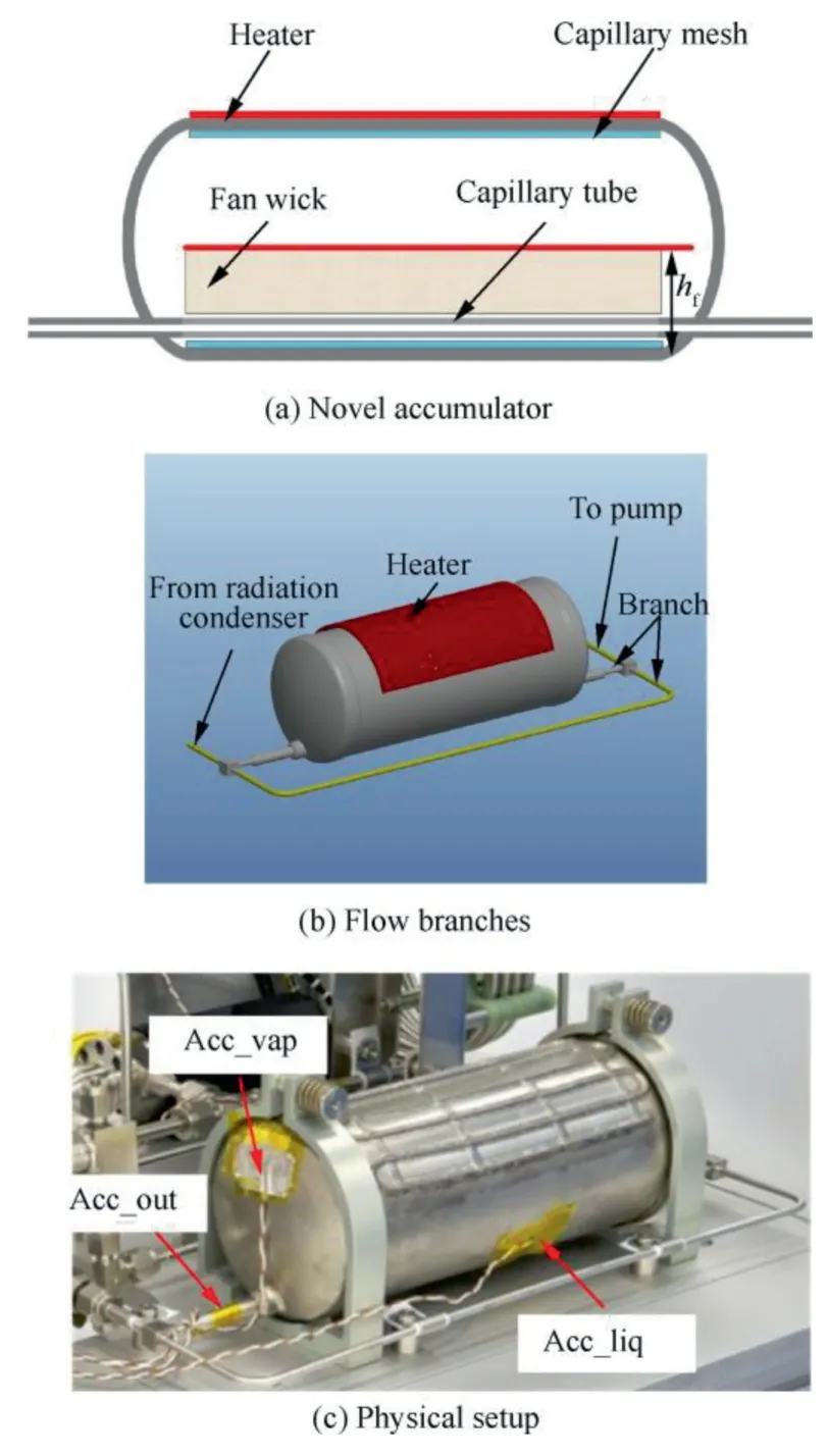
Fig.2 Schematic diagram of proposed novel accumulator,flow branches,and physical setup of accumulator.
In addition,to achieve the functions of heat exchange and liquid supplement of the capillary tube under micro-gravity applications,two more capillary structures,which are fan wick and capillary mesh,were introduced inside the accumulator.The capillary mesh was used to provide liquid to the inner surface of the accumulator for evaporating,and the fan wick was employed to gather liquid around the capillary tube to inhibit vapor from entering into the loop under microgravity.The fan wick was made of wire mesh with a large porosity.It is worth mentioning that the core function of the fan wick is to hitch the liquid around the inlet of the capillary tube rather than transport liquid to the capillary tube through the wick.Therefore,the fan wick is only used for space applications,and it is not necessary under the ground conditions.When the heat sources are loaded off,the amount of vapor between the evaporators and condenser will be decreased quickly.The evaporators and the tube located at the downstream cold-plates will be re-filled by the liquid from the accumulator,which will cause backflow from the accumulator to the main loop.In order to maintain the MPTL operating smoothly,the liquid inventory around the capillary tube should be larger than the amount required by the main loop in case of the load-off of all heat sources.
When heat is added to the accumulator,the capillary mesh must provide liquid to the accumulator’s heated surfaces for vaporization.The driving force which overcomes the flow resistance and the gravitational head is only the capillary pressure of the mesh.For the design of the capillary mesh,the maximum capillary pressure head ΔPc_max1should be higher than the sum of the pressure drop ΔPf1through the capillary structure and gravitational pressure drop ΔPgin ground application.That is:


The gravitational pressure drop in Eq.(2)disappears under the micro-gravity conditions.ΔPc_max1,ΔPf1,and ΔPgcan be expressed as.where σsis the surface tension coefficient;rcis the effective pore diameter of capillary structure,m;μlis the dynamic viscosity;Qis the heat power loaded on the accumulator;Δhlvis the latent heat;ΔLis the maximum transport length through the wick;ρlis the liquid density;Kis the wick permeability;ε is the porosity;lais the axial length;tis the wick thickness;Dais the diameter of accumulator.Moreover,the relation between the pressure drop and flow rate for the capillary mesh can be expressed as a form of Ref.32,as shown in Eq.(4).Combining Eqs.(2)-(5),one can obtain that the minimum thicknesses of the wick are 1.0 mm and 1.4 mm for ground and space applications,respectively.In this study,the thickness of this capillary structure was selected as 2.0 mm.
For the design of the capillary tube,the flow of working fluid through it should satisfy the following relation:

where ΔPc_max2and ΔPf2are the maximum capillary pressure of the pore and the pressure drop along the tube.ΔPc_max2can be obtained by Eq.(3),and ΔPf2can be calculated by.

wherefis the friction coefficient,which can be calculated by the Churchill formula;lc2is the length of tube,m;is the mass flow rate through the tube in the accumulator;dc2is the inner diameter of the capillary tube;Ac2is the cross-section area.
Moreover,another function of the capillary tube is to form a barrier via capillary force to avoid vapor permeating into the loop in case of orbit change or repositioning for satellite under in-orbit conditions.If vapor enters into the tube,the pump could be damaged and the operating and stability of the MPTL will be further impaired.
The function of fan wick is only retention of the liquid around the capillary tube and not transporting fluid through the wick.It is made of the felt wick material with a large diameter.The fan wick fits closely with the capillary tube,so the liquid in the accumulator can cover the capillary tube easily.In addition,the corners between the fan wick and the capillary tube can be used to collect the liquid by the capillary force,which will be beneficial for liquid entering into the main loopfrom the accumulator during the load-off of heat sources.In orbit,it needs to be assured that the complete wick is filled with liquid and the capillary tube is in contact with enough liquid zones to deliver the maximum amount of liquid.The total volume requested,the difference between the volume before and after shutdown,is 1.15 × 10⁻⁴m3.The volume should be located around the capillary tube in the volume below the red line indicated in Fig.2(a),whose heighthfis greater than 30.0 mm.In order to satisfy the manufacturing requirement for the fan wick,its thickness should be greater than 1.0 mm.In this study,the thickness is selected as 2.0 mm by considering the allowance.
The capillary structures are therefore of great importance for the MPTL system.Table 1 summarizes the design geometries and functions of the three capillary structures.It is worth noting that safety factors were also introduced when determining the design geometries.The material of the metal container was stainless steel 316L and the wall thickness was 3 mm.
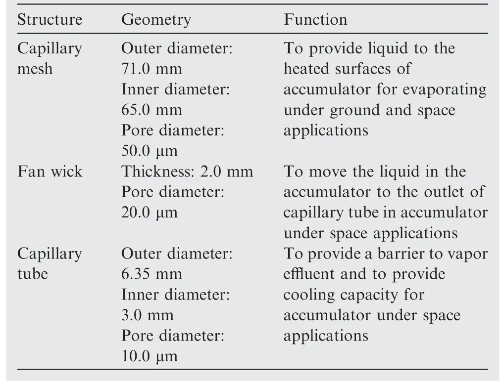
Table 1 Design geometries and functions of three capillary structures.
2.3.Experimental setup of MPTL
The assembly drawing of the proposed MPTL system for the space camera is displayed in Fig.3(a).Nine heat sources that are connected in series are employed to simulate the core optical detectors of the space camera.Particularly,the nine coldplates are manufactured by 3D printing.The power of each heat source is 5.0 W;that is,the total dissipating power for the MPTL system is 45.0 W.A centrifugal pump is used to transport the working fluid in the loop due to its advantages in a long lifetime,high reliability,and low maintenance cost.A plate heat exchanger is set to recover the heat from the heat sources so as to reduce the pre-heater power.A preheater is used to heat the sub-cooled liquid to the saturated state before it enters into the evaporators.A heater was also set at the outlet of the condenser to protect the pump from cold shock.In order to avoid vapor generation during the heating process,one power circuit of heating with the automatic temperaturecontrol function is designed and used.The temperature point is set as-25°C,which is much lower than the operating point(10–20°C).There is no possibility for vapor to generate in this section.Propane is selected as the working fluid due to its comparatively high-quality factor and suitable mass flow rate.33Several thermal-couples were pasted on the walls of each component.An Absolute Pressure Sensor (APS) was set to monitor the pressure variation in the accumulator.During the tests,all the measured data,such as temperatures and pressure,were recorded by the Agilent 34980 data acquisitions system.The uncertainties of temperature sensors and the APS were less than 0.1 °C and 2000 Pa,respectively.Table 2 gives the main parameters of the MPTL system.
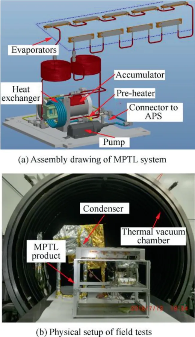
Fig.3 Assembly drawing of MPTL system and physical setup of field tests.
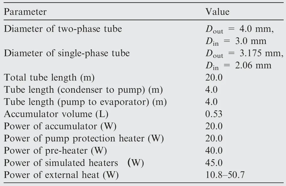
Table 2 Parameters of MPTL system.
In the present study,a thermal vacuum chamber was employed to simulate the working environment in the space.The physical setup of field tests is shown in Fig.3(b).During the tests in the thermal vacuum chamber,only the front surface of the condenser was exposed to the space environment.The vacuum degree of the vacuum chamber can reach 10-4–10-3Pa,and the convective heat transfer between the MPTL system and the space environment could be therefore omitted.The cold environment of the space was simulated by cooling the internal walls of thermal vacuum chamber with liquid nitrogen,and the wall temperature can reach that lower than-173 °C.Although the wall temperature was a little higher than that in the space,the difference in the radiant-heat exchange between these two conditions was less than 1%.Multilayer Insulation (MLI) blankets were packed at the back of the radiator to prevent heat loss.The MPTL setup was fixed on a platform,and a PTFE plate was used to insulate heat between the MPTL and the radiator.All the components of the MPTL system except the radiator were mounted in a small cabin whose temperature could be adjusted.In order to decrease the heat disturbance between adjacent components,all the components were packed with MLI blankets.
For space applications,the waste heat of the spacecraft is ultimately dissipated to space by infrared radiation through the radiator surface.As shown in Fig.4(a),an aluminum base plate with white paint on the front surface was selected as theradiator.The white paint on the front surface of the radiator has a high emissivity for infrared emission (ε >0.9) and a small infrared absorptivity for sunlight (α <0.2).The former can maximize the heat-dissipating to the sink while the latter can minimize the heat-absorbing from the sun.Fig.4(b) presents the structure of the back of the radiator.It consisted of the mounting grooves of the tubes,a heater,and the condenser tube.The condenser tube and the radiator were well thermally connected to quickly and efficiently dissipate the heat.Silicone rubber and hoops were employed to concatenate and fix the condenser tube with the mounting groove to decrease the thermal resistance between them.Besides the heat generated from the onboard equipment,the energy-absorbing from the space environment also affects the temperature of the radiator.A heater located at the red zone in Fig.4 was applied to simulate the external heat.

Fig.4 Radiator surface with white paint and layout of back of radiator.
2.4.Analyses of gravity independence in MPTL system
Except for the accumulator,the two-phase working fluid can also be found in the pipe between preheater and heat exchanger.In the present study,the performances of two-phase flow and heat transfer for MPTL system are conducted under terrestrial conditions.However,in the space environment,the MPTL is under microgravity condition.The effect of gravity on the flow boiling of MPTL is through buoyancy.Because of the large density difference between liquid and vapor,buoyancy will significantly influence the vapor motion relative to the liquid,the interphase velocity slip,and other flow characteristics arisen therefrom(such as pressure drop,heat transfer,etc.).34When reducing the gravity,the influences of buoyancy are attenuated;meanwhile,secondary forces (such as surface tension forces)which are usually insignificant under terrestrial conditions are expected to play an important role.35Due to the demand of the MPTL system in future spacecraft,two-phase flow boiling under microgravity (μg) conditions is needed to be considered.Simultaneously,theories and correlations have been derived to set up the criteria of gravity independence in the multiphase thermal fluid system.36–40From the space application’s point of view,if one can assure that the performance of the MPTL system is independent of gravity during the design process,the behavior of the heat and mass transfer under μg conditions can be tested and checked on the ground.Therefore,the characteristics of the two-phase flow and boiling heat transfer of the MPTL are analyzed by the criteria of gravity independence.
The two-phase flow in the tube is determined by surface tension force,inertia force,and gravity.In addition,the surface tension force and inertia force are the two common forces that can suppress gravity.Hence,one can infer that the twophase flow can be regarded as gravity independence if these two forces far exceed the gravitational force.In the present study,two dimensionless numbers,which are Bond number(Bo) and gas superficial Froude number (FrSG),are used to evaluate the effect of surface tension force and inertia force.BoandFrSGare given by.39

wheredis the inner diameter of tube;ρgis the gas density;USGis the gas superficial velocity.
By substituting the corresponding values into Eq.(8) and Eq.(9),Bo=2.64 andFrSG=2.63 to 4.60 are obtained.The critical values of these two dimensionless numbers to estimate the gravity independence are.39

In addition,there is flow boiling process occurring in the preheater and evaporators,and gravity also affects boiling heat transfer in these components.Zhang et al.40developed three criteria to estimate the gravity independence of flow boiling,which were: (A) overcoming the influence of hydrodynamic instability at the vapor–liquid interface by the perpendicular component of gravity to the heated wall;(B)overcoming the influence of vapor removal from the channel by the gravity component opposite to the direction of liquid flow;(C)ensuring that the wavelength related to the instability of the liquid–vapor interface is smaller than the heated length.
For Criterion(A),the influence of gravity becomes negligible when.

where θ is the angle between heat source and flow direction.It is 0° in the present study.By substituting the corresponding values into Eq.(12),the results show that the value of the left term ranges within 0.0006–0.02,which meet the demand.
The Criterion (B) can be judged in terms of the Froude number as.

Considering that the value of θ equals 0° in the present study,the value of left term therefore equals 0.The Criterion(B) is also satisfied.
The Criterion (B) can be evaluated by Weber number as.

whereleis the length of heat source.In the present study,the length of the flow channel of each evaporator is 0.35 m.By substituting the corresponding values into the left term in Eq.(14),one can obtain the values ranging between 2000 and 11703.The Criterion (C) is also satisfied.
In conclusion,the gravity impendence of the two-phase flow and heat transfer is certified based on the dominant force,interfacial wave in two-phase annular flow,and flooding in slug flow.The proposed MPTL meets the requirements of in-orbit application for spacecraft.
3.Results and discussion
3.1.Start-up behavior of MPTL system
Before the pump starts up,all the components except the accumulator should be full of liquid in order to avoid cavitation at the vanes and the bearing of the pump.However,it should be noted that the temperature of the whole system is almost the same before the first-time start-up in orbit,which leads to the fact that the vapor might distribute anywhere in the system.In order to liquefy the vapor,the saturated pressure of the MPTL should be firstly increased by heating the accumulator to a higher temperature.In the present study,the set temperature of the accumulator was 20.0 °C,which was about 22.0–25.0 °C higher than the initial temperature.
Fig.5 presents the temperature variation of the three measure points and power variation of the heater on the accumulator.As shown in Fig.5,the heating process began at 4500 s and the heating power quickly reached its maximum value of 20.0 W.The temperature rising of the vapor(Acc_vap) within the accumulator was faster than that of the liquid (Acc_lip)due to the differences in specific heat and mass.A temperature difference between the vapor and the liquid quickly formed during this process and the vapor in the main loop was liquefied because of the pressure rising.When the vapor temperature reached the set value,the pump started to work at 5586 s.At the same time,the subcooled liquid from the radiant condenser was pushed into the inlet of the accumulator,which supplied cooling capacity for the passive cooling.Then,the liquid temperature at the outlet of the accumulator (Acc_out)plunged to-7.0°C and a temperature difference of more than 15.0 °C can be observed between the gas and the liquid in the accumulator.The temperatures of outlet and liquid phase varied with the values of external heat load,while the temperature of vapor phase was influenced little by them and it kept stable.
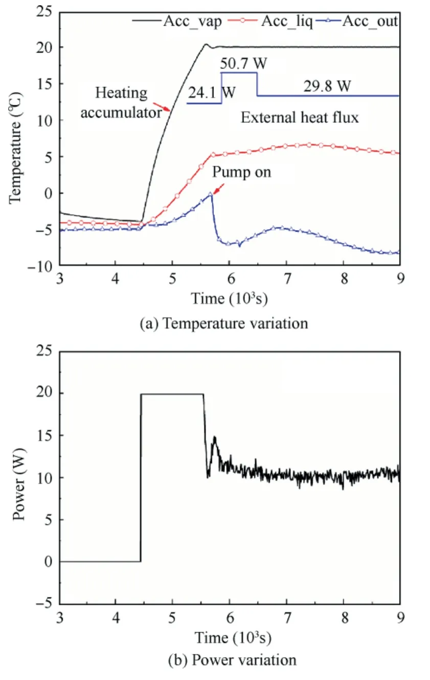
Fig.5 Overall variation in temperatures of three measure points on accumulator and temperature control power on accumulator during start-up of MPTL system.
By neglecting the transient terms of heat capacity for the solid structure of the accumulator and fluid in the accumulator during the stably running phase,the energy balance equations can be expressed as.

whereQHis the heating power on the accumulator;QCis the cooling capacity by the branch flowing into the accumulator;QLis the heat leakage from the accumulator to the mounting plate;QRis the radiation power from the accumulator to the environment.
The heat transfer process from the accumulator to the mounting plate is mainly through the heat conduction process.Four titanium alloy screws are used to fix the accumulator,soQLcan be calculated by.

wherekTiis the heat conductivity coefficient of titanium alloy;Ascrewis the area of screw;lscrewis the length of screw;Taccis temperature of average temperature of accumulator;Tpis the temperature of mounting plate.By substituting the values of the upper variables,the value ofQLin Eq.(16) is calculated as 0.50 W.
The accumulator is covered by MLI blankets,so the heat leakage through radiation can be expressed by.

where εeis the equivalent coefficient of radiation for the accumulator,and the value is 0.02;σ is the Stefan-Boltzmann constant;Ais the surface area of the accumulator;Teis the temperature of environment.By substituting the values into Eq.(17),QRis calculated as 0.05 W.
As shown in Fig.5(b),the heat power of the accumulator decreased from 20.0 W to about 10.0 W after the start-up of the pump.Combining Eqs.(15)-(17),one can conclude that the cooling capacity provided by the heat exchanger of the capillary tube is about 9.45 W.
Fig.6(a)presents temperature variation in the outlet of the pump,and the inlet and outlet of the preheater,(Pump,PH_in,and PH_out).Before the start of the pump,the temperatures of evaporators ranged between -7.0 °C and 0 °C due to the long-time exposure in the low-temperature environment in the cabin (ranged between -10.0 °C and 0 °C),as shown in Fig.6(b).A quick temperature drop can also be found at these locations after the pump started to work.The preheater started to work at 6130 s and the temperatures of preheater and evaporators increased quickly after that.However,two-phase flow phenomena did not appear due to the heat leakage from the MPTL system to the low-temperature cabin.
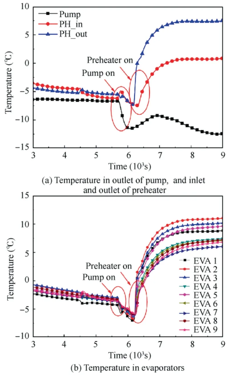
Fig.6 Temperature variation in outlet of pump,and inlet and outlet of preheater and evaporators during start-up of MPTL system.
Variation of vapor temperature and absolute pressure within the accumulator,as well as the fitting vapor temperature based on absolute pressure,are presented in Fig.7.Using the data of saturated pressure and saturated temperature from NIST standard reference database,41one can obtain the fitting correlation between them.As shown in Fig.7(a),the pressure quickly increased from 0.42 to 0.845 MPa after the start of the heating process and then almost stabilized at 0.845 MPa except for several oscillations during the phase-changing process.The trend agreed well with the vapor temperature in Fig.5(a).Besides,as shown in Fig.7(b),the fitting temperature agreed well with the measured vapor temperature although there was a temperature difference of 0.2–0.3 °C between them.In addition,the fitting vapor temperature is lower than the measured value due to the heating power and thermal resistance of the shell.Particularly it is proved that the saturated temperature/pressure within the accumulator is determined by the gas phase in it.
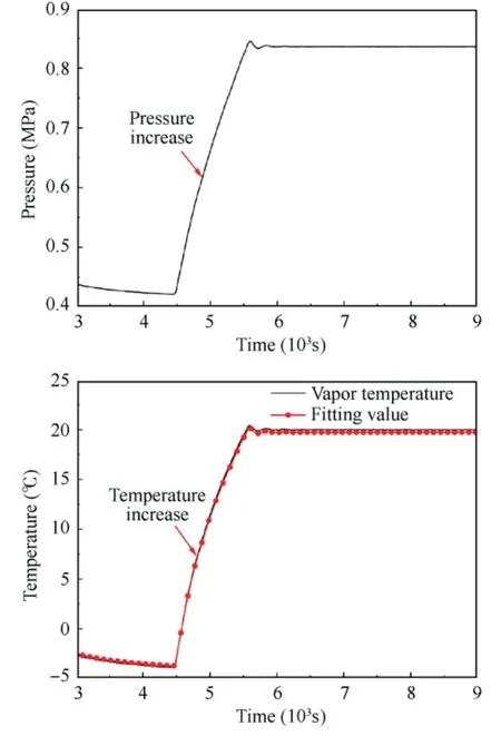
Fig.7 Variation in pressure in accumulator and vapor temperature and fitting temperature during start-up of MPTL system.
3.2.Phase changing behavior of MPTL system
Fig.8 presents the oscillation of temperatures,heating power and pressure during the phase changing of MPTL system.The pump protection heater located at the outlet of the condenser was started to increase the inlet temperature of the preheater at 9646 s.After that,as shown in Fig.8(a),temperaturerising can also be found at the outlet of the accumulator.At 10591 s,temperatures,heating power,and pressure oscillations can be found,which symbolized the occurrence of two-phase changing,that is,the working liquid changed from singlephase to two-phase.For the vapor temperature,it fluctuated in a small range,which was 19.6–20.5 °C.For the outlet temperature of the accumulator,it oscillated in a relatively big range,which was between -6.0 and 2.1 °C.Meanwhile,big oscillations in heating power,which ranged between 3.0 W and 12.0 W,were also observed to balance the vapor temperature.The pressure fluctuated between 0.827 MPa and 0.847 MPa during this process.Meanwhile,they shared a much close fluctuation in amplitude and frequency.As shown in Fig.8,the oscillation lasted for about 1600 s.After several oscillations,the temperature of each variable stabilized gradually.Oscillations during the phase-changing process also reflected that mass transfer and heat transfer simultaneously occurred between the main loop and accumulator.Reasons and details of the oscillations will be further discussed in Section 3.5.

Fig.8 Overall variation in temperatures of three measure points on accumulator,temperature control power on accumulator,pressure in accumulator,and vapor temperature and fitting temperature during phase change of MPTL system.
3.3.Operating stability of MPTL system
Temperature stability caused by heat sources load-on/off plays a key role in an MPTL.In the present study,the external heat with the maximum power of 50.7 W simultaneously loaded on with the heat sources to simulate the most demanding environments.Fig.9(a)presents the temperatures of the vapor and liquid within the accumulator and the outlet liquid temperature of the accumulator.The results show that the vapor temperature within the accumulator was slightly affected during this process while the liquid temperature within the accumulator and the outlet temperature of the accumulator were obviously influenced,because of the mass transfer process between the accumulator and the main loop.The outlet temperature of the accumulator,as well as the liquid temperature within the accumulator,firstly decreased because more subcooled liquid from the condenser flowed into the accumulator due to more vapor generated when the heat sources was loaded on.Similarly,the instantaneous increase of outlet temperature of the accumulator after the heat sources loaded off can be explained in the same way.After that,the outlet temperature of the accumulator continuously increased when the heat sources were loaded on and increased first and then decreased when the heat sources were loaded off.However,oscillations which are presented in detail in Fig.9(b) can be found in the temperatures of vapor and outlet of the accumulator.The results show that the vapor temperature first increased and then decreased after the heat sources loaded on.Such a trend is because vapor fraction within the main loop increased after the heat sources loaded on,and then more liquid was therefore pushed into the accumulator,which further compressed the vapor space within the accumulator and increased the vapor pressure.Considering that the saturated temperature is linearly correlated with the saturated pressure,the vapor temperature,therefore,increased with the increase of vapor pressure.
It can be predicted that the heat and mass transfer between the accumulator and the main loop was enhanced due to bigger pressure,which decreased the inlet temperature of the preheater and therefore decreased the inlet dryness of the evaporator;meanwhile,the heating power of the accumulator was also decreased due to the temperature rising.Above interaction leads to the temperature decrease of vapor temperature.Accordingly,the trends of vapor temperature after the heat sources loaded off can be explained in a similar way.
However,the oscillations of the vapor temperature and the outlet temperature of the accumulator were moderate after heat sources loaded off.The small mass flow rate,from the accumulator to the main loop,was responsible for that.
Variations in temperatures of the inlet and outlet of the heat exchanger and the nine evaporators are displayed in Fig.10.The variation of external heat power is shown as the black line with solid squares in Fig.10(a).The results show that the outlet temperature of the liquid at the cold side of the heat exchanger (the graphic symbol of HX_cold_out in Fig.10(a))can be heated to 19.0–20.5°C after exchanging heat with the two-phase flow from the evaporators.Compared with the inlet temperature(the symbol of HX_cold_in in Fig.10(a)),the liquid temperature achieved an increase of 7.0–12.0 °C by setting a heat exchanger in the main loop,which saved the power of the preheater.Meanwhile,Fig.10 indicates that the setting of the heat exchanger can provide a relatively stable inlet temperature during the whole process despite there was a temperature rise of about 1.5°C after the heat sources loaded on.The inlet temperature of the heat exchanger at the cold side shared the same variations but with smaller oscillations with the outlet of the accumulator.It is because the oscillations were buffered by the pump.
For the hot side,the inlet temperature (the symbol of HX_hot_in in Fig.10(a))varied little during the whole process,which demonstrated that the working fluid was always in the two-phase state from another aspect.However,the outlet temperature of the exchanger (the symbol of HX_hot_out in Fig.10(a)) was greatly influenced by the heat sources.A big temperature increase was observed after the heat sources loaded on.It is because the loading of the heat sources increased the dryness of the working fluid at the inlet of the exchanger,and therefore increased the latent heat which can be released by the working fluid.
As shown in Fig.10(b),the temperatures of the nine simulated evaporators ranged between 21.5 °C and 23.0 °C,which were 1.5–3.0 °C higher than the vapor temperature within the accumulator.The higher temperature was caused by the higher pressure due to the pressure boost by the pump.In detail,the temperatures ranged between 21.5 °C and 22.5°C during heat sources load-off while increased to 22.0–22.5°C,despite small oscillations,after heat sources loaded on.Besides,the temperatures of the evaporators were influenced little by the variation of external heat flux.
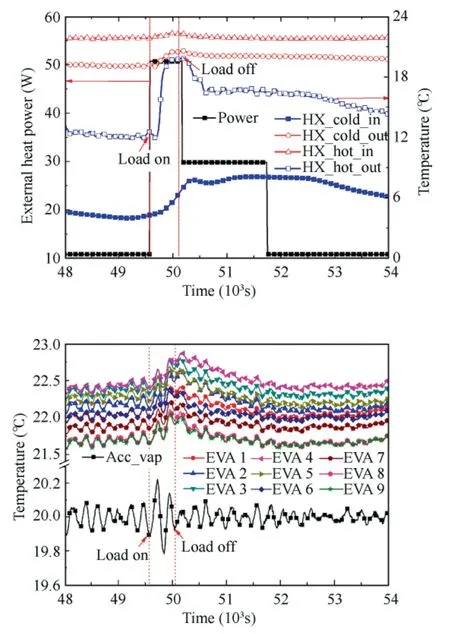
Fig.10 Temperature variations in heat exchanger and evaporators and vapor in accumulator during heat load-on/off.
Summing up the above,during the heat sources loaded-on/off,the proposed accumulator can generate a stable temperature boundary condition for the main loop and therefore ensured a stable evaporating temperature.
3.4.Temperature adjusting behavior
Normally,the temperature control point of the MPTL system is fixed.However,considering that the MPTL system would operate in orbit for more than ten years,the system will be required to adjust the temperature control point when power supplied by the solar panel attenuated or the working conditions of electronic components are needed to change.Fig.11 shows the variations in temperatures,pressure,and power in key components during the temperature control point adjusting process.What’s more,the start-up process of the MPTL system in Fig.11 is similar to that in Section 3.1,and the reasons for these oscillations are omitted here.
As shown in Fig.11(a),the temperature control point of the accumulator changed to 10 °C at 15486 s.The heating power of the accumulator plunged to zero just at this moment.Then,the temperatures within the accumulator gradually decreased to set value with time.As mentioned before,passive cooling was achieved by the heat exchanging process between the capillary tube with super-cooled liquid and the liquid phase in the accumulator.Hence,the gradient of temperature decrease was nearly linear under the circumstances,and the value was 0.223 °C/min.Even so,the adjusting process lasted for about 44.9 min and the vapor temperature reached the set value at 18180 s.After that,the vapor temperature within the accumulator remained stable and ensured a constant working boundary for the heat sources.
In addition,because there was no phase-changing that occurred during this process,the temperatures of the liquid within the accumulator,the outlet of the accumulator,and the evaporators all gradually decreased,and no oscillations were observed.Besides,the pressure within the accumulator also gradually decreased with time.It was because,without heating,the vapor was liquefied by the subcooled liquid at the contact surface,which decreased the vapor temperature because of the heat exchanging and increased the specific volume of the vapor due to the density difference between the vapor and the liquid.Accordingly,the pressure decreased by the interaction of temperature decrease and vapor increase.However,because the heat exchange rate between the vapor and the liquid within the accumulator was limited,the descent gradients of pressure and temperature were slow.Therefore,as shown in Fig.11(b),the fitting temperature based on pressure also always closely followed the real value.
Fig.11(c) shows the variation of temperatures in the evaporators.The results showed that the temperatures of evaporators had the same trend as the vapor temperature.After the start-up process,the fluid in the evaporators was in a twophase state,which was controlled by the accumulator.Hence,the temperatures of evaporators changed with that of the accumulator.However,some differences between them were due to the heat leakage between the evaporators and cabin.After the cooling process,all the temperatures within the evaporators kept constant.The temperatures of evaporators are 1.3–2.7 °C higher than the vapor temperature of the accumulator.The temperature differences between the two types of components are mainly caused by the saturated pressure differences between them.
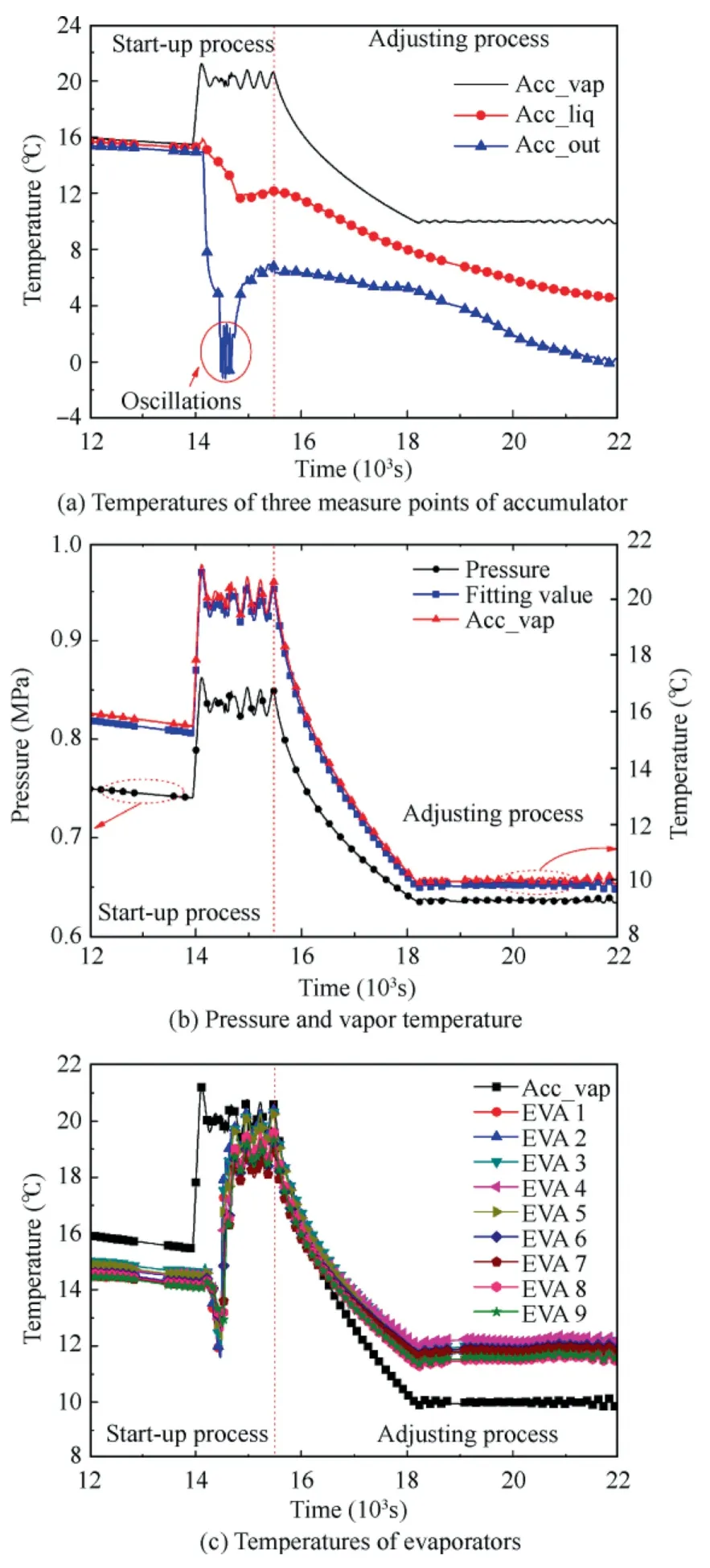
Fig.11 Variation in temperatures of three measure points of accumulator,pressure and vapor temperature of accumulator and fitting temperature from saturated pressure,and temperatures of evaporators during temperature control point adjusting process.
3.5.Analyses of oscillation process
Along with the merits in performance,there also are some challenges in predicting several design parameters,such as heat transfer coefficient and pressure drop.42Besides,the instability phenomenon of the thermally induced two-phase flow is also of great interest in the design and operation of many twophase systems.43Boure et al.44earliest and influentially reviewed important distinctions of the two-phase instability between the static and dynamic instabilities.The predicting methods for the frequency of dynamic instabilities were also suggested.Kakac and Bon43summed up the dynamic instabilities in tube boiling systems and found that most theoretical models to predict the instabilities were clarified by the solution examples and validated by the experiments.Ruspini et al.45summarized the experimental and theoretical results for each kind of instability and introduced the instability mechanisms in triggering and sustaining the two-phase flow.Recently,O’Neil and Mudawar42systematically overviewed the fundamental occurrence mechanisms which dominated the two-phase instabilities in macro-and micro-channel systems during the boiling process.They pointed out that the internal and external pressure curves were still the best intermediaries in predicting the instabilities in system level.As a two-phase heat transfer system and shown in Section 3.1,MPTL is prone to instability during the process of phase change.
Fig.12 shows,in detail,the oscillations that have been presented in Fig.8 in temperature and pressure during the phasechanging process.Because of the big vapor–liquid density ratio of propane,just at the moment of phase-changing,more liquid downstream of the main loop was pushed into the accumulator,which enhanced the passive cooling and led to the decrease of outlet temperature from PointBto PointC.As shown in Fig.12(a),the outlet temperature dropped from -2.1 °C to-6.2 °C during this process.Meanwhile,as shown in Fig.12(b)and Fig.12(c),both the vapor temperature and the pressure of the accumulator increased from PointBto point C due to the compression of the vapor space by the inrush of liquid.Moreover,the heating power of the accumulator also decreased to 2.5 W because of the increase in vapor temperature.
When the pressure within the accumulator reached the maximum value at PointC,more ‘‘hot” fluid from the accumulator was compressed into the main loop.Consequently,as shown in Fig.12(a),the outlet temperature of the accumulator gradually increased after that.Meanwhile,the vapor temperature and the pressure of the accumulator began to decrease because of the increase of the vapor volume.And the heating power of the accumulator began to increase as it reached its minimum value at PointC.With the interaction of the low heating power and expansion of the vapor phase,the vapor temperature decreased to its minimum value of 19.6 °C.And the new point B was generated at this moment.After that,the extra liquid will be pushed into the accumulator again and begin the next cycle.It is obvious that because of the alternate motions of increasing and decreasing in the process of mass transfer between the accumulator and main loop,the temperatures,pressure,and heating power of the accumulator oscillated many times during the phase-changing process.All the parameters finally reached to dynamic stability when the mass transfer process also oscillated regularly.
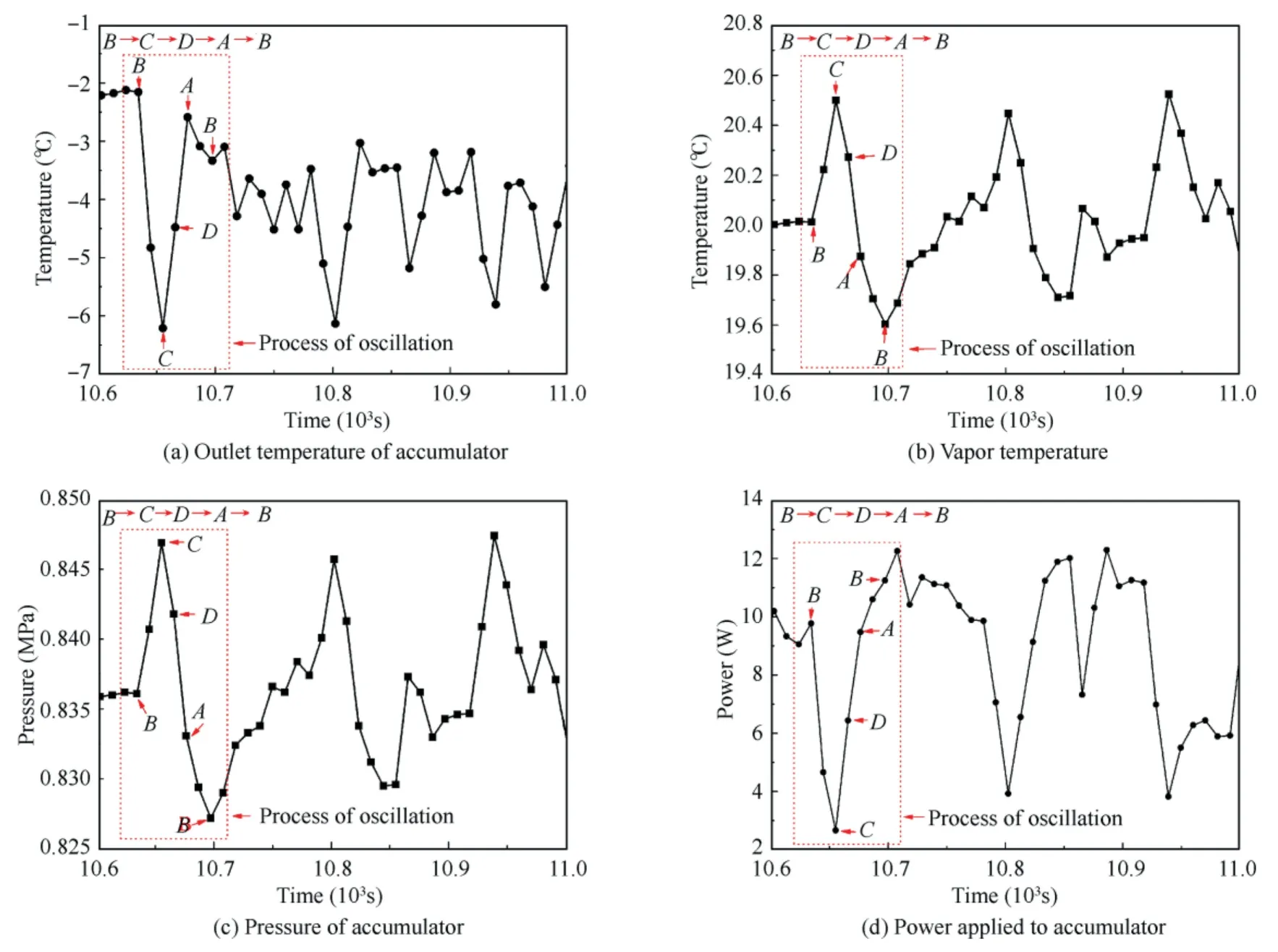
Fig.12 Oscillation in outlet temperature of accumulator,vapor temperature,pressure of accumulator,and power applied to accumulator.
In the present study,the accumulator has a compressible volume and the slope of the internal pressure is negative.These two characteristics within the accumulator led to Pressure Drop Oscillations (PDOs) during the phase changing process.In order to analyze the mechanism of PDOs,the schematic diagram of the flow and the cycle of the PDOs are presented in Fig.13.When there is no mass transfer between the main loop and the accumulator,MPTL operates in the middle of the negative slope region(PointP)and the liquid level in the accumulator is constant.Under this condition,the mass flow rate of steady state satisfies.

Fig.13 Schematic diagram of flow and cycle of PDOs.


where ΔPis the pressure drop of system;Ktis the equivalent friction coefficient,-.
The alphabetsAtoDin Fig.12 correspond to the locations in Fig.13.When the liquid in the main loop turns into the twophase state,will be higher thanand extra fluid with flow rate ofwill flow into the accumulator.Accordingly,the equivalent friction coefficient in Eq.(18)will increase,and the operating point will move up until it reaches PointB.If the pressure drop increases continually,the operation point will further move to PointC,where it will turn to a single-phase state.At PointC,the mass flow rate that enters into the preheater exceeds the amount that can be changed to a twophase state.Therefore,the pressure of the accumulator decreases to PointD.The extra fluid with a flow rate ofwill flow from the accumulator to the loop.Meanwhile,the low pressure will remain only if the rate decreases to the value at PointAwhere the mass flowing out the accumulator is less than that entering.After that,the pressure increases to PointBagain.That is any perturbation that is applied to two-phase region with a negative slope in pressure will lead to a flow cycle asB-C-D-A-B.The oscillations stop and tend to be stable after the stop of the mass transfer process between the accumulator and the main loop.
4.Conclusions
In the present study,a proposed MPTL setup for space camera was tested under the simulated space conditions.Particularly,a novel accumulator with passive cooling was designed as a temperature-controlled device.Transient behavior of the accumulator and the main loop during phase changing,heat sources load-on/off,and temperature control point changing were presented and discussed in detail.The main conclusions were drawn as follows:
(1) The passive cooling capacity of novel accumulator was achieved with assistance of the capillary tube in the accumulator,whose design got rid of the external cooling components of Peltier and structures.Compared with the traditional design,the novel accumulator has the features of simpler design,lower power consumption and higher reliability.
(2) Vapor temperature within the accumulator reached its set value in a short time while the other temperature points varied during the whole start-up process.Meanwhile,oscillations can be found in temperatures,pressure,and heating power during the phase changing process.The type of the oscillation of the system was PWOs,which was due to the presence of a compressible accumulator and an internal pressure curve with negative-slope portion.In spite of this,the proposed MPTL managed to control the oscillation within a small value.
(3) When the heat sources loaded on/off,despite several oscillations occurring,the MPTL managed to control the temperature variation within 1.0 °C.Heat and mass transfer between the accumulator and the main loop contributed to temperature stability.
Declaration of Competing Interest
The authors declare that they have no known competing financial interests or personal relationships that could have appeared to influence the work reported in this paper.
Acknowledgements
The work was supported by the National Natural Science Foundation of China (No.51806010) and Shanghai Sailing Program,China (No.18YF1409100).
 CHINESE JOURNAL OF AERONAUTICS2022年12期
- CHINESE JOURNAL OF AERONAUTICS的其它文章
- Control and utilization of range-dependent beampattern with waveform diverse array radars
- Airside pressure drop characteristics of three analogous serpentine tube heat exchangers considering heat transfer for aero-engine cooling
- Numerical analysis of deflection control of a gas plasma jet based on magnetohydrodynamic staggered electrode configuration
- Neural network-based model predictive control with fuzzy-SQP optimization for direct thrust control of turbofan engine
- Method for utilizing PIV to investigate high curvature and acceleration boundary layer flows around the compressor blade leading edge
- Experimental investigation of expansion effect on shock wave boundary layer interaction near a compression ramp
