Numerical analysis of deflection control of a gas plasma jet based on magnetohydrodynamic staggered electrode configuration
Jingjia ZHANG,Junwei LI,Zelin ZHANG,Zhijun WEI
School of Aerospace,Beijing Institute of Technology,Beijing 100081,China
KEYWORDS Deflection angle;Deflection control;Gas plasma;Magnetohydrodynamic;Thrust vector
Abstract To control the deflection of the gas plasma jet,a new analytical method is proposed based on the Magnetohydrodynamic (MHD) technique.Based on the typical MHD power generation model,the applied voltage is applied to the staggered electrodes,that is,a pair of electrodes on the same side wall are connected to generate an axial current in the channel.Under the action of the magnetic field perpendicular to the direction of the flow,the plasma is subjected to electromagnetic forces perpendicular to these two directions,and the jet is deflected.The computational model including the Navier-Stokes equations coupled with electromagnetic source terms,the electric potential equation and Ohm’s law is solved.The deflection of the gas jet under the action of an electromagnetic field is observed,and the maximum deflection angle is about 14.8°.The influences of the electric field,magnetic field,and conductivity on the jet deflection are studied.Results show that although the influences of these three factors on the deflection are similar,and the effect of increasing the electric field strength is slightly greater,priority should be given to increasing the magnetic field strength from the perspective of reducing energy consumption.The Stuart number is introduced to assess the ability of electromagnetic force to control jet deflection.When the electromagnetic parameters are constant,this solution provides better control of low-density and low-speed fluid flows.The calculation results show that using the staggered electrode method configuration is feasible in terms of controlling the deflection of a plasma jet deflection.
1.Introduction
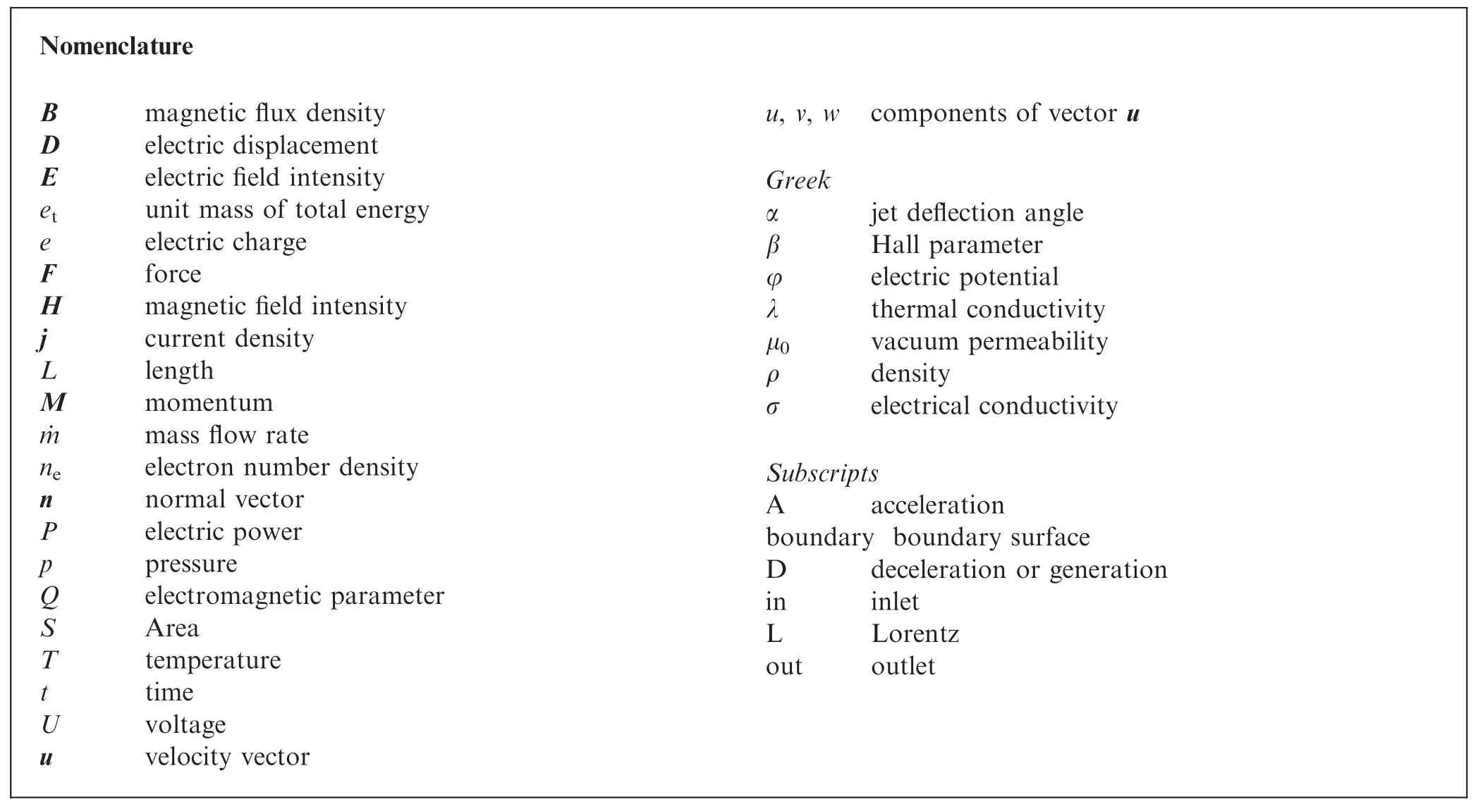
Thrust vector control aims to generate thrust components by actively controlling the deflection of the engine exhaust jet to replace the traditional control surfaces found on an aircraft or enhance its control performance,which will become one of the key techniques used in aerospace engineering.At present,the methods of controlling the deflection of a gas jet are mainly divided into two categories: mechanical1and fluidic,2and the available jet deflection angle is usually 7°–20°.The mechanical structure is subject to erosion by hightemperature gas,and the complicated control device has an adverse effect on the reliability of the engine.The fluidic method requires additional bleed air or exhaust devices,which is not conducive to the compact design of the engine.In recent years,as the active control of aircraft by electromagnetic fields has become a research hotspot,3,4there is the potential to use Magnetohydrodynamic (MHD) methods to provide thrust vectors for aircraft.
MHD is a subject that combines classical hydrodynamics and electrodynamics methods to explore the laws of motion of conductive fluids in electromagnetic fields and their interactions.In terms of aerospace engineering,Resler and Sear5first proposed the concept of magneto-aerodynamics and pointed out that it can be used to accelerate or decelerate conductive fluid in the channel.Restricted by the electromagnetic technology of that time,the related research mainly focused on ground MHD power generation6and high enthalpy hypersonic wind tunnels.7Until the 1990 s,Gurijanov and Harsha8proposed the idea of MHD energy bypass (AJAX),which transfers the kinetic energy of high-speed incoming flow to the engine in the form of electrical energy to extend the working range of traditional ramjets.Inspired by this pioneering work,scholars from various countries have investigated the application of MHD technology,including MHD combined turbo-ramjet engines,9hypersonic vehicle MHD power generation,10,11MHD enhanced propulsion,12,13inlet shock wave control,14–16and hypersonic vehicle thermal protection systems.17,18
Compared with traditional mechanical and fluidic solutions,plasma flow control has the advantages of a rapid response,high reliability,and a simple structure;however,current research into the use of MHD to achieve thrust vector control remains limited.The method proposed by Borovskoi et al.19,20involves the deflection of the magnetic field through a certain angle on the basis of the typical MHD power generation model,so that the induced electromagnetic force will decelerate the gas plasma while changing the direction of the flow.By changing the angle between the magnetic field and the axis of the engine,it is possible to change the direction of a conducting flow in multi-branch pipes or to control the direction of the thrust vector in flight vehicle.Shneider and Macheret21introduced the application of MHD method to aerodynamic control and thrust vectoring.A set of MHD power generation devices are installed at the outlet of the engine nozzle,and the deflection moment can be formed by decelerating the gas on one side,thereby realising thrust vectoring.Taking the low-speed gas containing Cs2CO3ionisation seeds as the research object,Zhao et al.22,23placed a pair of permanent magnets outside the rectangular channel and observed the deflection of the jet at different gas temperatures.He explained that the ions are deflected by the Lorentz force and transfer momentum to neutral molecules,while the momentum of the electrons is ignored due to their small mass.
The discussion of the interaction between the flow and electromagnetic fields in the above work remains limited.At the same time,to ensure the control effect,the plasma must have a sufficiently high flow velocity.In the present work,a method of controlling the deflection of a jet with MHD staggered electrodes is proposed.Based on the typical MHD power generation model,a voltage is applied to the electrode on the same side: due to the conductive properties of the plasma,this pair of electrodes will be turned on and a current along the direction of jet flow is generated.Under the action of the magnetic field perpendicular to the direction of flow,the electromagnetic volume force perpendicular to both must act on the plasma at this time,which in turn causes the jet to deflect.The core of this scheme is to apply an electric field to introduce a suitable axial current into the channel,and the effect of jet deflection can be flexibly adjusted by changing the intensity of the electric and magnetic fields.Since the electric field induced in the plasma flow is perpendicular to the applied electric field,the lateral Lorentz force is largely independent of the flow velocity,and does not change the original momentum.
2.Method and mechanism
The magnitude of the Lorentz force in MHD is determined by the current density j and the applied magnetic field B,that is,FL=j×B.The current density is given by the general form of Ohm’s law:

The right-hand term of the formula automatically ignores the electronic pressure term (σ/ne)·e·grad(pe) and the inertial effect -τdj/dt(τ is average time between collisions),which are only obvious in the case of strong shock waves and extremely high collision frequencies.24It can be seen from the above formula that the current density is affected by the applied electric field E,induced electric field u×B,and Hall parameter β.In Section 2.1 we describe the working principles of different applications of MHD in combination with Eq.(1).
2.1.Mechanism underpinning action of an MHD generator
MHD power generation is the most basic application in MHD.In this mode,the plasma flow direction,electric field direction,and magnetic field direction are mutually perpendicular(Fig.1(a)).The gas with conductivity σ flows perpendicular to the magnetic field B=(0,0,Bz)at speed u to generate an induced electric field-uBzalong they-axis,and a load with an electric field strength of E=(0,Ey,0) is connected between the two electrodes.In this mode,since the induced electric field is dominant,that isuBz>Ey,the current in the channel is aligned with the induced electric field.The magnetic fluid device outputs electrical energy j·E to the load;and at the same time,the induced current generates the Lorentz force FLopposing motion of the fluid under the action of the magnetic field,decelerating the flow.In the figure,u′is the velocity vector after the action of MHD.
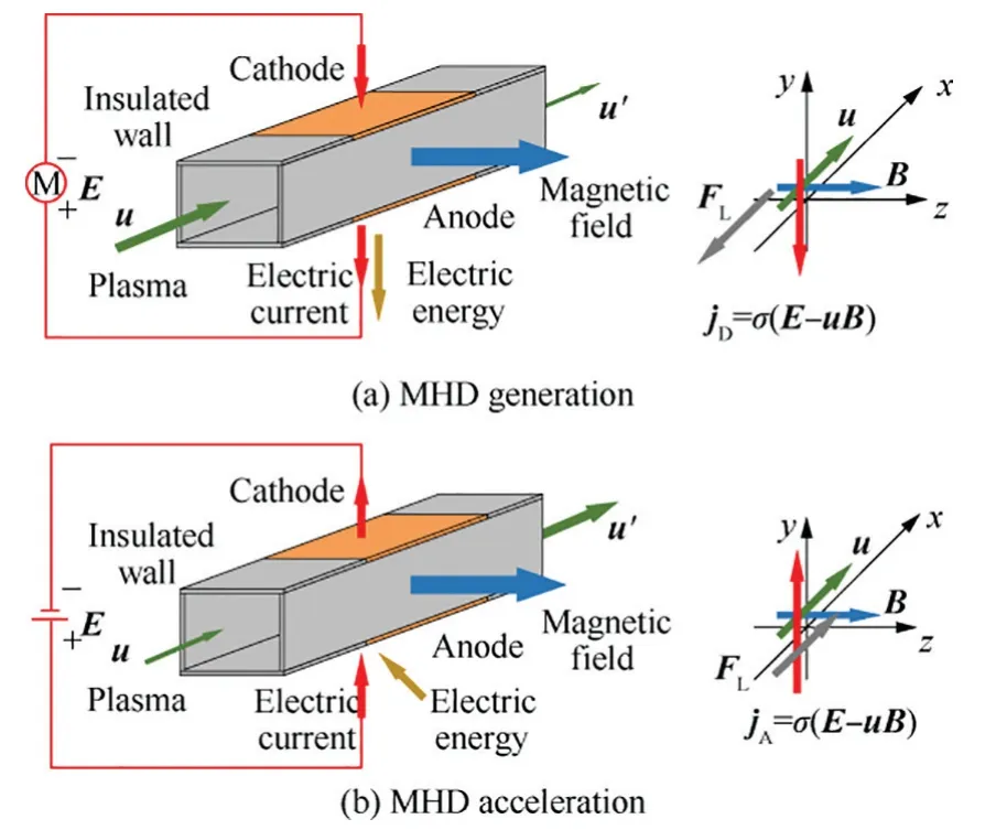
Fig.1 Schematic diagram of MHD power generation and acceleration.
2.2.Mechanism of MHD acceleration
The mechanism of MHD acceleration is similar to the power generation (Fig.1(b)),except that the magnetic fluid device is connected to a power source with an electric field strength E instead of a load.In this mode,the applied electric field dominates,that isEy>uBz,so the current in the channel is conducted along the direction of the applied electric field.External electrical energy will be injected into the magnetic fluid device,and the current will generate the same Lorentz force FLas the fluid motion under the action of the magnetic field to accelerate the gas.
2.3.Mechanism of MHD jet deflection control
On the basis of MHD power generation and acceleration,several solutions for jet deflection control have been developed(Fig.2).Fig.2(a) shows the principle of MHD in terms of uneven acceleration and deceleration in the exertion of jet control,whose essence is to accelerate or decelerate the plasma in different regions.There are several pairs of electrodes installed in the channel (only two pairs are shown in the figure),which can be independently controlled to accelerate or decelerate.When it is necessary to control the deflection of the jet,one pair of electrodes is set to power-generation mode,and the other to acceleration mode.Under the action of this asymmetric electromagnetic force,a momentumMyalong theydirection is generated.21In this solution,to ensure sufficient torque,the plasma in the channel is required to have a large velocity and the nozzle must have a certain width.
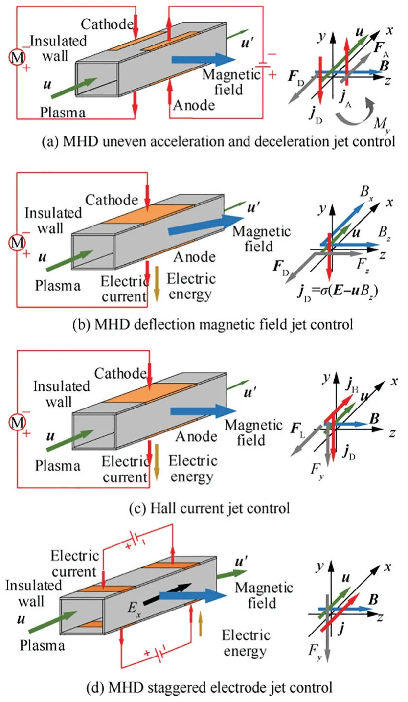
Fig.2 Schematic diagram of different MHD control methods.
Fig.2(b) is a schematic diagram of the MHD deflection magnetic field jet control system.The scheme is designed to make the magnetic field rotate through a certain angle around they-axis based on the power-generation mode.At this time,the magnetic field B=(Bx,0,Bz) not only has az-direction component,but also anx-direction component.In this case,only the magnetic field in thez-direction contributes to the induced current,that is,jy=σ(Ey-uBz).Due to the rotation of the magnetic field,the Lorentz force acting on the plasma has two effects,a deceleration opposing the flowjyBzand the deflection force perpendicular to the axis -jyBx.The lateral deflection force generated in this scheme is necessarily accompanied by flow deceleration,and its magnitude is affected by the magnetic field component.19In fact,it is relatively difficult to increase the strength of the magnetic field and change the direction of the magnetic field.
Fig.2(c)presents a schematic diagram using Hall current to control jet deflection.From Eq.(1),we can see that the current is not only affected by the applied electric field and induced electric field,but also related to the Hall parameter.In this scheme,the Hall current is the dominant force,the essence of the Hall effect is that the mobility of electrons is much greater than that of ions.When the influence of the Hall effect is considered,there will also be a Hall current jH=(-β/|B|)·(j × B) in thex-direction in the channel,which generates an electromagnetic force in they-direction under the action of the magnetic field.In this scheme,the Hall parameters are affected by the jet composition and the environment,and are not easy to control.More importantly,the Hall effect will concentrate the current on the edge of the electrodes,causing significant heating.
The principle of the MHD staggered electrodes jet control method proposed in this paper is shown in Fig.2(d).In this scheme,the external electricExfield plays a major role.A pair of electrodes on the same side wall are connected to the power source,and the gas plasma in the channel is conducted along the flow direction at this time.Under the action of the magnetic field B,the plasma is deflected by Lorentz force -jxBzin they-direction.This solution can flexibly control the deflection of the jet by changing the intensity of the electric field or the magnetic field(this does not affect the original momentum and neither require the jet to have a high velocity).
3.Numerical method
3.1.Plasma acquisition
The MHD problem (the magnetic fluid referred to herein is equivalent to plasma) requires the fluid to have a certain conductivity.To obtain sufficient conductivity,artificial ionisation is generally required.There are mainly two methods used in current research: external ionisation and thermal ionisation.External ionisation technology can be used when the gas temperature is low,mainly including electron beam ionisation,high-voltage nanosecond pulse discharge,and microwave discharge.The plasma obtained by this method is inhomogeneous,and the electrons will recombine far from the area of ionisation.When the temperature of the gas is high(>2500 K),thermal ionisation can be used.Due to the low ionisation potential of alkali metals,adding alkali metal substances to the gas as ionisation seeds means that the metal readily loses electrons and induces gas ionisation.The plasma obtained by the thermal ionisation method is both uniform and stable.
In the present work,the high-temperature gas containing an alkali metal salt is taken as the research object,and the degree of ionisation is usually 10-6to 10-3(a weakly ionised plasma).Under this condition,the charged particles are surrounded by many neutral molecules,and the electromagnetic force acting thereon will be transferred to the neutral molecules through collisions.In the MHD problem,the motion characteristics of a specific particle are no longer considered separately,but the conductive properties of the gas plasma are described by the macroscopic conductivity σ,which is affected by the gas temperature and pressure.25,26In fact,since the mobility of electrons is much greater than that of ions,the flow process is accompanied by the Hall effect.Its strength can be characterised by Hall parameter β=σ|B|/(ene),which is usually related to electron number density and magnetic field strength.
3.2.MHD equations
For the magnetic fluid,the most basic governing equation is used to couple the electromagnetic source term based on the Navier-Stokes equation to obtain the full MHD equations.27To simplify the calculation,the dimensionless magnetic Reynolds number is introduced:

where μ0is the vacuum permeability,σ denotes the electrical conductivity,Lcis the characteristic length,anducrepresents the characteristic velocity.The magnetic Reynolds number can be regarded as the ratio of the intensity of the induced magnetic field b to the applied magnetic field B,which characterizes the degree of distortion of the magnetic field.
Under typical working conditions (Rem=0.01),the induced magnetic field of the magnetic fluid is much smaller than the external magnetic field.Therefore,ignoring the influence of the induced electric field,the MHD control equations under a low magnetic Reynolds number are obtained28:

where U is the conservation vector,F,G,and H are respectively the convective flux vector in thex,y,andz-directions,Fv,Gv,and Hvare the viscous flux vectors,and SMHDis the MHD electromagnetic source term.Their expressions are shown below,

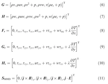
whereetis unit mass of total energy,τijis the viscous stress,λ is the thermal conductivity.
Compared with the general Navier-Stokes equation,the low magnetic Reynolds number equations introduce new variables current density j and electric field intensity E.To ensure that the equations are closed,the electric field equations need to be solved.Maxwell’s equations are:

Under the hypothesis of a low magnetic Reynolds number,further neglecting the change of the applied magnetic field with time,the right-hand term in Eq.(12) in the equations is zero,which means the curl of electric field is 0.The electric field is a conservative field,so the potential function must be used to describe this variable.The electric potential φ can be expressed as.

In the non-relativistic problem,the displacement current caused by the residual charge is very small relative to the induced current and the conduction current can be ignored.29So if we take the curl at both ends of Eq.(13),Eq.(1) will simultaneously lead to the Poisson equation of electric potential30:

There are two types of boundary conditions for the potential equation: conductive walls and insulating walls.For conductive walls,you can specify the current density on the electrode,or the potential value φ0on a given electrode.Usually,the latter is easier to obtain and simple to calculate,so.

For the insulating wall,no current flows through the wall,that is j·n=0.Substitute this into the potential equation to get.

where n is the normal vector to the boundary.
3.3.Code validation
To verify the mathematical model of the low magnetic Reynolds number MHD equations,the numerical value and experimental results are compared below.Bogdanoff and Mehta31and others from NASA Ames Research Center established the MHD accelerated test system,which uses shock waves to drive air and mixes K2CO3therein to increase the conductivity,and obtained a plasma gas (σ ≈120 S/m) that satisfies the requirements imposed on the test temperature and pressure.The numerical calculation conditions refer to the experimental conditions and the work of other researchers.32The magnetic field is considered uniform throughout the acceleration working period,and has an intensity of 0.92 T.In the Ref.33,to avoid the need to calculate the sheath voltage,uniform electric fields of different strengths are used to replace the voltage drop between the plates.The composition change is not considered in the calculation process,and the gas satisfies the ideal gas equation and Sutherland’s formula.
Fig.3 depicts the pressure distribution diagram on the axis of the MHD channel,where the points in the diagram are the test results,and the curve is a plot of the results of numerical calculation.Ucapacitoris the voltage between the two electrodes,whileEyrepresents the corresponding electric field strength(excluding the effect of the electrode sheath).Note that the nominal inlet conditions of the three tests are theoretically the same.It can be seen from the figure that the pressure will gradually decrease with the flow;however,under the combined action of the electromagnetic field,as the applied voltage increases,the pressure drop happens at a lower rate.This is due to the Joule heating effect,which offsets the drop in static pressure caused by the acceleration of the flow,which is consistent with the test results.As shown in Fig.4.The average velocity increment at Electrode 19 under different capacitance voltages is compared:when the capacitor voltage is 380 V,the speed increases by about 40%;when the voltage is 320 V,the speed increases by 28%.The calculation results are in good agreement with the results of the test and Gupta and Agarwal.34Due to the complicated flow process in MHD acceleration,lack of detailed experimental data,rough simplification,and uncertainty around some parameters,there are still some discrepancies between the calculated and experimental results,yet the key data and the overall trend are consistent.Although the following calculation conditions(density,velocity,acceleration and deflection,etc.) are different from the test,the assumptions and governing equations currently used are applicable.And the model is also used21,35to study the deflection of the plasma jet under the electromagnetic field.Therefore,the low magnetic Reynolds number MHD model is considered reasonable.
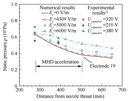
Fig.3 Pressure distribution along axis of MHD channel.
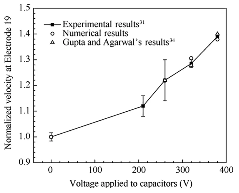
Fig.4 Dimensionless velocity of Electrode 19 under different capacitance voltages.
3.4.Computational model and conditions
Referring to the model in the Ref.36,as shown in Fig.5,the calculation model used in the present work is a 3D model indicating the relationship between flow and electromagnetic field.When calculating the volume-related quantity in the following text,the channel width is 2Lw=20 mm.Using a right-handed Cartesian coordinate system,the plasma gas with temperatureT=3000 K and conductivity σ enters the channel at a speed u,and then enters the atmosphere after passing through the constant cross-section and expansion channel.Since the temperature and pressure of the gas do not change much,the conductivity here is the average value in the channel.35In individual cases,the Joule heating effect will heat up the local gas,and its impact has not been considered yet.The expansion channel is adopted to ensure that there is space for the jet to deflect.Its inlet height is 2Lhi=20 mm,outlet height is 2Lhe=30 mm,length isLl=35 mm,and the expansion half angle is about 8.1°.The upper and lower walls of the entrance and exit of the expansion section each have attached thereto a pair of electrodes of lengthLe=2.5 mm regardless of thickness,and energy can be injected into the channel during operation.The rest of the walls are ideal insulating walls,and the wall temperature isTw=1500 K.It is assumed that there is a uniform and stable magnetic field B along thez-direction of the channel.The gas satisfies the ideal gas equation of state,and the chemical reaction of the plasma in the channel is not considered.The main variable parameters in the paper include incoming flow velocityuin,conductivity,voltage,magnetic field strengthB,etc.The calculation conditions are summarised in Table 1.
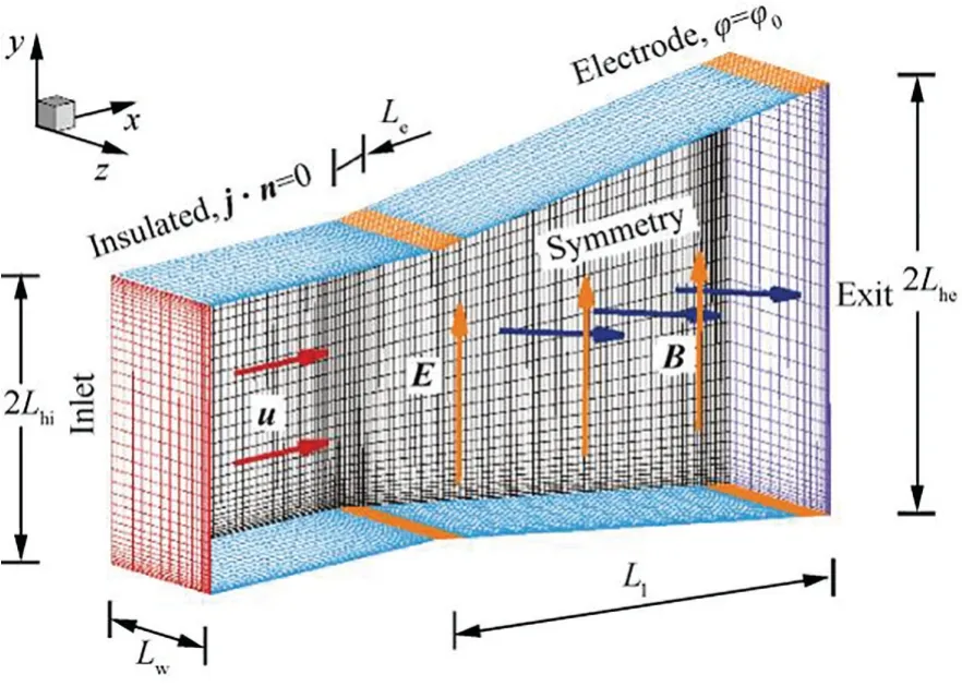
Fig.5 MHD gas jet deflection model diagram.
3.5.Grid independency
The calculation of the current density near the edge of the electrode and the heat transfer process of the surface layer on the wall are sensitive to the size of the grid and need to be encrypted.To eliminate the influence of the grid on the calculation results,three cases with different meshes are analysed.According to the height of the first layer of the grid,we calculate the dimensionless parametery+,and take values 1,2,and 5.Taking the MHD acceleration mode as an example,the voltage of the first group of electrodes isU=50 V,the Hall parameter is β=0.5,and the heat flux on the wall can be calculated byqw=h(Tw-T∞),wherehis the heat transfer coefficient,T∞is gas temperature.In the calculation,it is ensured that the residual value of each variable is smaller than 10-6,and the relative flow deviation of the inlet and outlet is<10-5.The result is shown in Fig.6.
Fig.6 illustrates the heat flux and current density distribution curve on the upper wall of the channel.The pair of electrodes can be turned on under the action of an external electric field,and the current is concentrated on the edge of the plate.Due to the influence of the Hall effect,a short circuit is formed at the edge of the electrode plate,which significantly increases the current density on one side.This is why segmented Faraday electrodes are usually used.In the atmospheric environment,the radius of rotation of electrons is restricted by neutral molecules,and the free path of electrons is reduced,37generally β<0.2.Moreover,the electrode width is limited(Le/Ll<0.1),so the electric field in the main electromagnetic area is not greatly affected by the Hall effect.For the sake of simplicity,the following calculations will not consider the effect of the Hall effect.Wheny+≈2,the distributions of heat flux and current density tend to converge,and this grid number is used in the subsequent calculations.
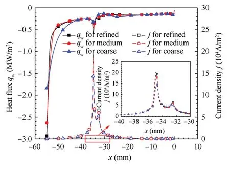
Fig.6 Distributions of current density and wall flux with different meshes.
4.Results and discussion
4.1.Simulation of MHD staggered electrode configuration
Take Case 1 in Table 1 as an example to analyse the flow process of the MHD staggered electrode configuration:the potential distribution in the channel is shown in Fig.7,and the channel is divided into three areas.This part of Zone 1 is far from the electrode,and the gas plasma is mainly affected by the induced electric field.Positive ions and electrons are separated by Lorentz force under the action of a magnetic field per-pendicular to the flow.The polarisation of the plasma will inevitably produce an electric field to prevent the further separation of positive ions and electrons to maintain a quasi-neutral state.This electric field is the Faraday electric field.Since the incoming flow velocity is low and the induced electric field is small,Δφ=uB·2Lhi=2 V can be deduced.Zone 2 is the main electromagnetic action area.The electric field distribution can be calculated by solving the electric potential gradient.The electric field intensity distribution is uniform and mainly along thex-direction.This is also the main source of the lateral electromagnetic force in this scheme.Zone 3 is the area near the electrode,which is subject to a large potential gradient,and the direction thereof is from the electrode to Zone 2,or vice versa.
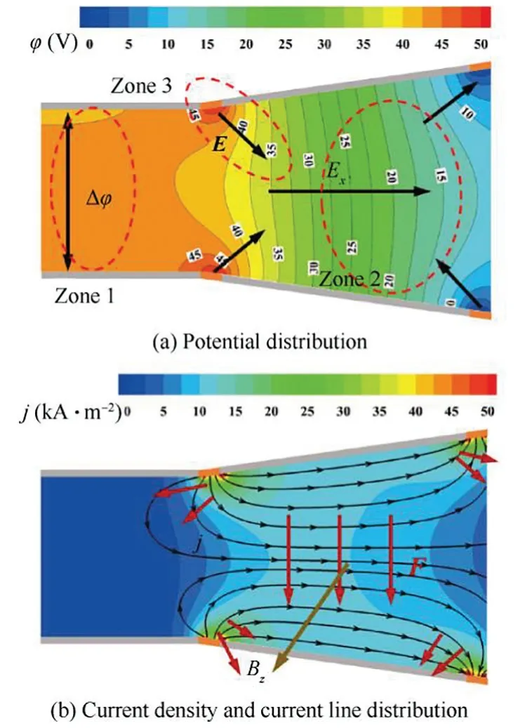
Fig.7 Parameter distribution in channel of Case 1.

Table 1 Salient model parameters.
Fig.7(b)shows the current distribution in the channel.The current starts from the positive pole and flows through the expansion channel to the negative pole located at the outlet.It can be seen in the figure that in the main electromagnetic zone (Zone 2),the current is almost distributed along the axis of the channel.The magnetic field B is along thez-direction,and it is inferred from the direction of the current that the direction of the Lorentz force on the fluid is downward.In this way,the gas plasma is able to gain momentum in theydirection and produce deflection under the action of the applied electromagnetic force.In the vicinity of the electrode(Zone 3),the current line is no longer in thex-direction but perpendicular to the direction of the electrode plate,so that the fluid near the upper electrode at the outlet is accelerated,and the fluid near the lower electrode is decelerated.The purpose of deflecting the jet is to increase the momentum of the jet in they-direction,and the Lorentz force near the electrode may weaken the deflection effect.Although this area is limited,its influence cannot be easily ignored due to the large current density and the location and the vicinity of the outlet.
To explore the influence of this part,the magnetic field is only applied to Zone 2 (the calculation conditions are those shown in Case 2,whereB=1 T corresponds to Case 2.1 andB=-1 T corresponds to Case 2.2).This treatment eliminates the influence of electromagnetic force on the gas plasma near the electrode.The velocity distribution after changing the magnetic field action area is shown in Fig.8:the jet is deflected downwards after passing through the electromagnetic field.Define the local velocity deflection angle θuon the exit section as the ratio of the local velocityvin they-direction to the velocityuin thex-direction,that is,tan θu=v/u.Fig.9 shows the velocity and its deflection angle distribution on the exit section of the channel,where the negative deflection angle represents downward deflection.The velocity deflection angle near the wall varies to a significant extent,which is not shown in the figure for the sake of clarity.When there is no magnetic field,the velocity and deflection angle are symmetrical with respect toy=0 mm,indicating that the total momentum in they-direction is 0,and the jet remains undeflected.In the presence of the electromagnetic effect,the peak velocities in Cases 1 and 2.1 are increased,the maximum velocity is about 78 m/s,and the mainstream zone is close to the downward wall.In Case 2.1,a zone of negative velocity appears near the upper wall,indicating that backflow has occurred.The velocity deflection angle in these two cases is no longer symmetrical either,and both tend to deflect downwards.Compared with Case 1,the magnitude and range of velocity deflection angle in Case 2.1 are greater than in the former case.The point where the deflection angle is 0° in Case 1 appears neary=6 mm.At that time,a part of the positive mainstream velocity deflection angle remains,which offsets a part of the downward deflection;however,in Case 2.1,when the angle is 0°,the corresponding velocity is not in the mainstream zone.It can be inferred from the figure that the effect of jet deflection is augmented after changing the range of the applied magnetic field.
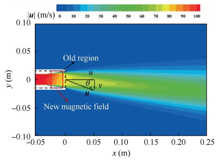
Fig.8 Velocity distribution of Case 2.
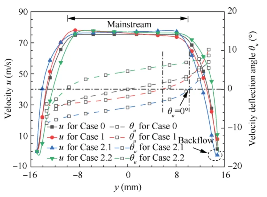
Fig.9 Velocity and deflection angle distribution at exit of channel.
To intuitively describe the jet deflection effect,the jet vector angle is defined macroscopically,that is,α=arctan(Fy/Fx),which is determined by the thrust on the nozzle exit,whereFx=∫ρuudSexit,Fy=∫ρuvdSexit,Sexitis the face vector of the exit and its direction is the same as the flow direction.Finally,the jet vector angles of Cases 1 and 2.1 are calculated to be-1.22°and-4.47°,respectively.Fig.9 also illustrates the results of changing the direction of the magnetic field (Case 2.2),which is completely opposite to the results of Case 2.1,which shows that changing the direction of the magnetic field can cause the opposite jet deflection effect.
Unlike the MHD acceleration and power generation mode,the Lorentz force in this scheme is mainly perpendicular to the jet flow direction.Its main purpose is to generate lateral momentum to deflect the jet and do limited work on the fluid,however,to maintain the magnitude of the electromagnetic force,a certain intensity of current is required,and the energy injected into the channel is mainly released in the form of Joule heating.The power consumed by the deflection process in this calculation condition is about 255 W.
4.2.Effects of electromagnetic parameters
The possibility of controlling the jet deflection by the staggered electrodes is analysed above,and the factors affecting the degree of jet deflection are discussed.The main factors affecting the magnitude of the lateral electromagnetic force are electrical conductivity,magnetic field strength,and electric field strength.Considering the case of a free jet,we assume that a unit volume of plasma with a density of ρ and a conductivity of σ passes through a distance of lengthLat a speed u.In this process,there is always a uniform electric fieldExand a uniform magnetic fieldBz,and finally the gas obtains momentum in they-direction,jxBzL/u=σExBzL/u=σBzUx/u,Uxis the voltage in thexdirection.Therefore,under certain conditions of incoming flow,the amount of deflection is related to the product of conductivity,voltage,and magnetic field.The influence of each factor will be discussed in detail below.
(1) Effect of electric field strength
Upon changing the voltage between the two pairs of electrodes,the effects on the calculated results under different electric field strengths are investigated,as shown in Case 3 in Table 1.Fig.10 shows the pressure distribution on the upper wallpupand lower wallspdownunder different electric field strengths.Under the action of a lateral electromagnetic force,the pressure on the lower wall increases while the pressure on the upper wall decreases,so that the upper and lower walls are subject to a pressure difference (the shaded area in the figure).As the intensity of the electric field increases,the pressure difference between the upper and lower walls will continue to increase.As the pressure on the lower wall increases,the adverse pressure gradient near the wall of the expansion channel will be increased further.Fig.11(a) shows the velocity and streamline distribution diagram whenU=250 V.Under the influence of the adverse pressure gradient,the flow near the lower wall is suppressed,the flow velocity decreases,and vortices appear.At the channel exit,the gas plasma flows downward under the action of the applied electromagnetic force,flow separation occurs on the upper wall surface,and backflow occurs.It can also be seen from the figure that near the lower wall of the outlet,the deflection of the jet is restrained by the wall.It is possible to improve the deflection effect through reasonable design of the channel shape.
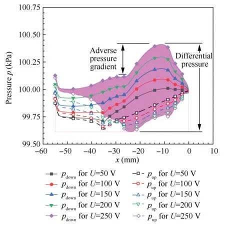
Fig.10 Pressure distribution on upper and lower walls.

Table 2 Calculated results at different St.
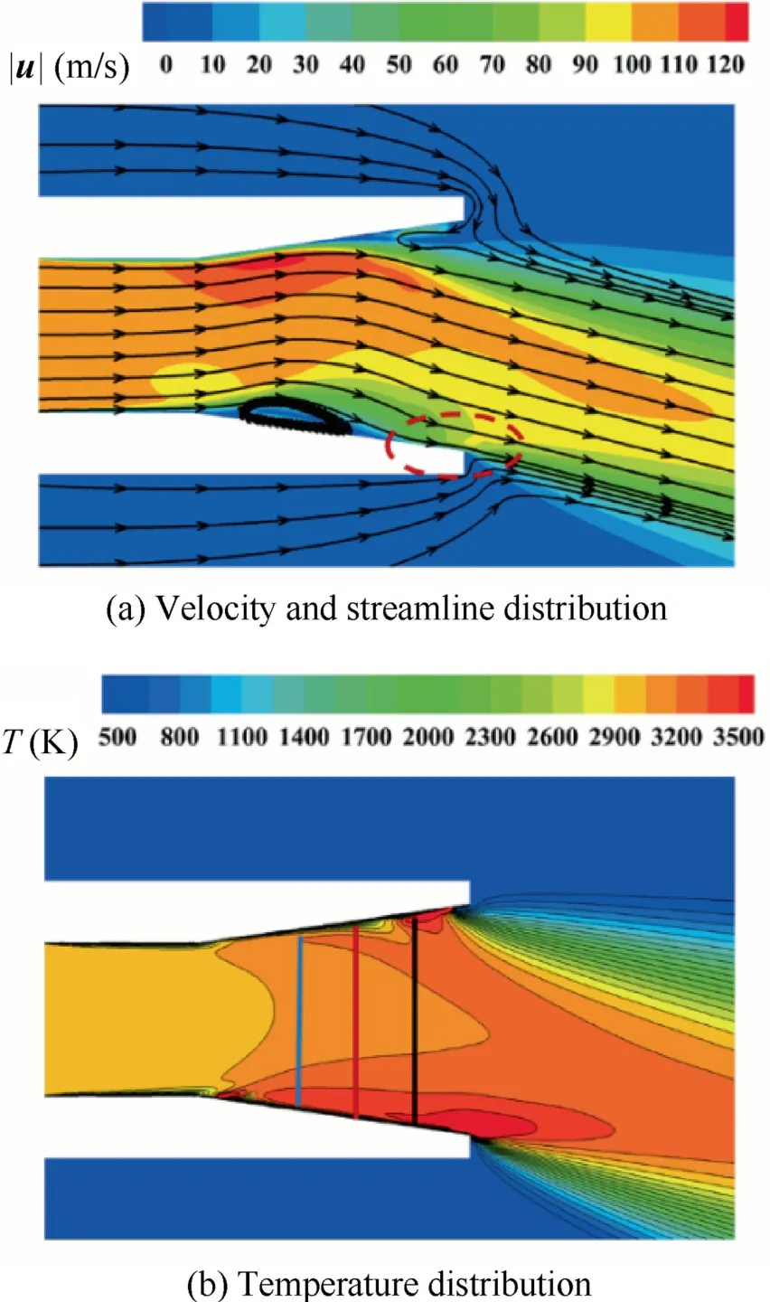
Fig.11 Calculated results when U=250 V.
In addition to Lorentz force,another phenomenon is Joule heating.Fig.11(b) demonstrates a contour map of temperature distribution.Increasing the voltage between the electrodes improves the jet deflection effect,but also generates significant Joule heat.The injection of Joule heat will significantly increase the temperature of the jet,especially near the electrode.Take the temperature and current density distributions on the three lines in Fig.11(b),the results are shown in Fig.12: the current density distribution in the channel is not uniform in they-direction.The current density is large near the wall,while it is relatively small in the central area.This causes the temperature near the wall to rise (the highest temperature thereat even exceeds 3500 K),which also leads to the difficulties with the thermal protection of the shell.On the other hand,the current density in the channel is not symmetric abouty=0,and the value in the lower half is higher than that in the upper half.This is because the flow separation produces backflow,which implies that the area of the electrode exposed to the gas is reduced (that is,the actual conduction area of the electrode),so more current will be conducted from the lower electrode.
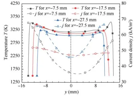
Fig.12 Temperature and current density curve in y-direction.
Fig.13 shows the velocity profile and deflection angle distribution on the exit.With the increase of the electric field intensity,the main jet flow area further tilts toward the lower half of this area,and the peak velocity and velocity deflection angle amplitude also increase.WhenU>50 V,the velocity deflection angle in the mainstream zone is almost always negative.Compared with the absence of MHD,the peak velocity increased by 38.7%,and the maximum velocity deflection angle is 16.3°.
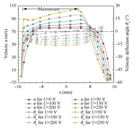
Fig.13 Velocity and deflection angle distribution at exit from channel (Case 3).
Fig.14 demonstrates the relationship between different electric field strengths,thrust,and deflection angle,where the thrust is the calculation result of unit channel width,and the same processing method is also used later.As the voltage increases,the jet deflection angle increases monotonically,following a quasi-linear relationship.The maximum deflection angle (as evinced by the current calculation) can reach 14.75°.For comparison,the maximum deflection angle calculated in Borovskoi and Vorozhtsov’s scheme19is less than 10°,while that of Zhao et al.23is about 12°.Shneider and Macheret21proposes the concept but does not give a specific deflection angle.
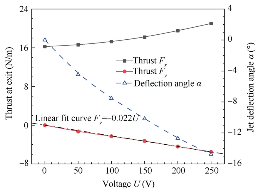
Fig.14 Thrust and jet deflection angle with different electric fields.
Observing the outlet thrust in thex-direction of different electric fields,it is found that in this scheme,Fxis not decreased due to the increased deflection: on the contrary,it is slightly improved due to the injection of energy.The thrust in they-direction and the applied electric field follow a linear relationship,which is consistent with the conclusion of the previous approximate analysis.TakingU=50 V as an example,Fx=5 N/m is estimated,which is greater than the calculated result.This is because the previous analysis assumes that the jet is in a free state,but the actual calculation should consider that the gas flow is constrained by the two side walls,and the electric field intensity in the channel is non-uniform.
(2) Effects of magnetic field and conductivity
Based on the previous results,it can be inferred that the deflection of the jet and the magnetic field strength and conductivity should also follow a quasi-linear relationship,that is,it has a linear relationship with the product of electric field strength,magnetic field strength,and conductivity.Using the parameters of Case 1 as reference values,we define the dimensionless electromagnetic parameterQ=σUB/The relationship between the tangent value of the deflection angle and the power consumption corresponding to different electromagnetic parameters is illustrated in Fig.15: independently increasing one of the three parameters can increase the deflection of the jet.When the dimensionlessQis constant,increasing the electric field strength alone has the greatest effect on the deflection,followed by those when increasing the conductivity and magnetic field.WhenQ=5,the deflection tangent values of the latter two are respectively 94.4% and 82.3% of that when changing the electric field.
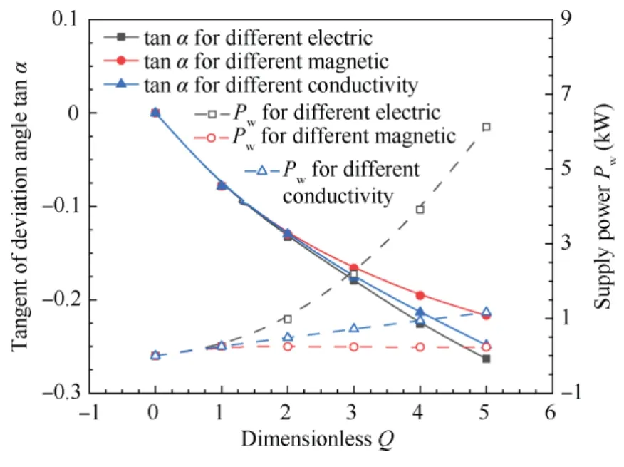
Fig.15 Deflection angle and power of different electromagnetic parameters Q.
It can be seen from the previous analysis that the three factors have similar effects on the jet deflection angle,but the power consumption involved is quite different.Increasing the intensity of the magnetic field can directly increase the electromagnetic force acting on the plasma without affecting the Joule heating.Assuming the power consumed to maintain the magnetic field is not considered,the energy consumed is constant.In the calculation,the effective area of the electrode is reduced due to the deflection,and the power drops slightly.This also explains why,as the magnetic field increases,the increase in deflection angle decreases slightly.The electric energy injected into the gas is mainly used to generate Joule heat,that is,P=|j|2/σ=σ·|E|2.When the electric field strength is constant,the power consumption follows a linear relationship with the conductivity;but when the conductivity is constant,the power is proportional to the square of the voltage,which means that as the increasing electric field improves the control effect,the energy consumption is also rising rapidly.WhenQ=5,the energy consumed by increasing the electric field is 26.4 and 5.26 times that when increasing the magnetic field and conductivity,respectively.
Therefore,to control the gas plasma jet,the conductivity should be increased as much as possible.On this basis,we should first consider increasing the magnetic field strength.Although increasing the voltage to the same degree can achieve better results,it is more advantageous to increase the magnetic field strength compared to the huge increase in energy consumption otherwise incurred.
4.3.Effects of flow velocity
The momentum of the gas jet will also affect the deflection.Fig.16(a) shows the velocity and deflection angle distribution at the exit,where the velocity is normalised.Whenuin=150 m/s,the normalised velocity does not change much,and the maximum value is 0.74,however,the deflection angle is no longer symmetrical.When θu=0°,the corresponding position isy=6.3 mm,which remains within the mainstream zone.As the incoming flow velocity decreases,the maximum normalised velocity gradually increases,and the point at which θu=0° gradually moves to the right.When the incoming velocity is 75 m/s and 50 m/s,the maximum values ofu/uinare 0.82 and 0.90,and the maximum values of θuare -10° and-14.5°.Fig.16(b) shows the pressure distribution,where the solid line represents the pressure on the upper and lower wallspwall,and the dotted line represents the differential pressure Δp.Due to the electromagnetic force,the pressure on the lower wall is higher than that on the upper wall.Asuinincreases,the peak differential pressure decreases from 165 Pa to 105 Pa,but the locus of the peak pressure shifts towards the nozzle outlet.
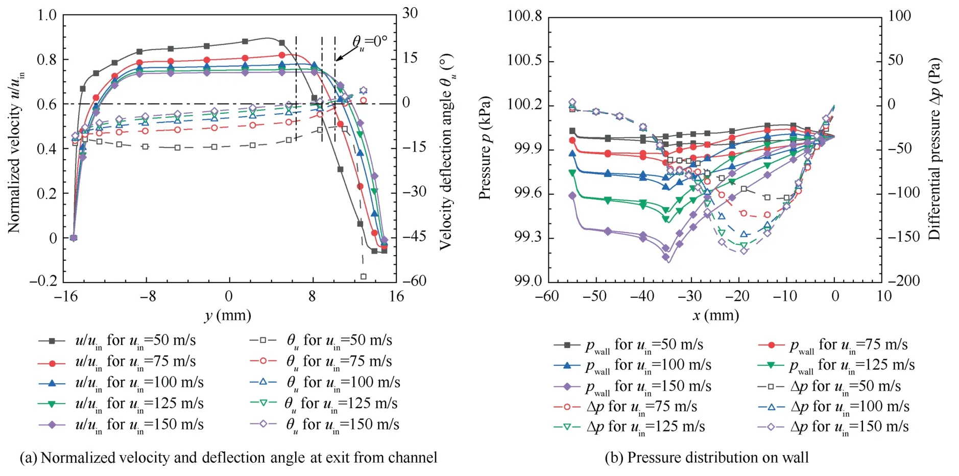
Fig.16 Calculated results of Case 5.
To describe the relationship between the incoming momentum and the deflection effect,the Stuart number is introduced,which is defined asSt=σBU/ρu2,and its physical meaning in this article is the ratio of the momentum of the jet in theydirection to the momentum at the inlet.The calculated results at differentStare listed in Table 2.For linear regression ofStand tan α,the correlation coefficientR2>0.9,implying that the two have a good correlation,andStcan be used to evaluate the degree of jet deflection.It is worth noting that the precise jet deflection angle cannot be obtained byStalone because,according to the previous analysis,even ifStis the same,the deflection effect is slightly different.By the same token,Stis unrelated to power consumption.The power consumption will increase slightly asStincreases,which is also affected by the degree of jet deflection.
To a certain extent,Streflects the ability to control jet deflection:the larger it is,the stronger its influence on the deflection of the jet.When the electric field,magnetic field,and conductivity are constant,Stis inversely proportional to the square of the density and the incoming velocity.For flows with low density and low speed,this control method is more effective.In addition,multiple pairs of electrodes are added to act simultaneously to increaseSt,but at this time,the electrode arrangement and channel structure need to be considered.
5.Conclusions
A staggered electrode configuration to control the deflection of a gas plasma jet is proposed based on the MHD technique.Through numerical analysis,the interaction between the plasma and electromagnetic field is studied.The influences of electric field strength,magnetic field strength,electrical conductivity,and incoming momentum on the deflection of the jet are analysed.The following conclusions are obtained:
(1) Using the proposed staggered electrode configuration,the phenomenon of jet deflection is observed,and the maximum deflection angle is about 14.8°,which shows that the scheme is feasible in terms of its ability to control the plasma jet deflection.Compared with the traditional control methods,the control effect obtained by this scheme is at the same level as the former.The advantage of this scheme is that it can avoid direct contact with high temperature gas and reduce the complexity of the mechanical structure.The Lorentz force at the edge of the electrode may weaken the deflection effect,so electric and magnetic fields should be arranged in an appropriate manner.
(2) The dimensionless electromagnetic parameterQis defined,and it is found that the degree of jet deflection is approximately linearly related toQ.Increasing the electric field,magnetic field,or conductivity can increase the deflection of the jet.The first has the greater effect,but at the cost of greater energy consumption.From the perspective of reducing power consumption,priority should be given to increasing the magnetic field strength.
(3)Stis introduced,and it is found that it can be used to evaluate the ability of the electromagnetic field to control the deflection of the jet.The largerStthe stronger its ability to control the jet.When the three electromagnetic parameters are constant,the control effect of this scheme is better for jets with low density and low velocity.
For future work,reasonable optimization of the electromagnetic field layout may be one of the directions.Furthermore,the miniaturization of equipment and the development of ionization technology will also promote the application of this scheme.
Declaration of Competing Interest
The authors declare that they have no known competing financial interests or personal relationships that could have appeared to influence the work reported in this paper.
 CHINESE JOURNAL OF AERONAUTICS2022年12期
- CHINESE JOURNAL OF AERONAUTICS的其它文章
- Control and utilization of range-dependent beampattern with waveform diverse array radars
- Airside pressure drop characteristics of three analogous serpentine tube heat exchangers considering heat transfer for aero-engine cooling
- Neural network-based model predictive control with fuzzy-SQP optimization for direct thrust control of turbofan engine
- Method for utilizing PIV to investigate high curvature and acceleration boundary layer flows around the compressor blade leading edge
- Experimental investigation of expansion effect on shock wave boundary layer interaction near a compression ramp
- Experimental study on dynamic behavior of mechanically pumped two-phase loop with a novel accumulator in simulated space environment
