Composite anti-disturbance position and attitude control for spacecrafts with parametric uncertainty and flexible vibration
Zengbo LIU ,Yukai ZHU ,Jianzhong QIAO
a School of Automation Science and Electrical Engineering,Beihang University,Beijing 100191,China
b Beijing Institute of Control Engineering,Beijing 100190,China
c School of Astronautics,Beihang University,Beijing 100191,China
d Peng Cheng Laboratory,Shenzhen 518055,China
KEYWORDS Composite anti-disturbance control;Flexible vibration;Parametric uncertainty;Spacecraft position and attitude tracking;Tumbling non-cooperative target
Abstract The rendezvous and proximity operations with respect to a tumbling non-cooperative target pose high requirement for the position and attitude control accuracy of servicing spacecraft.However,multiple disturbances including parametric uncertainties,flexible vibration,and unknown nonlinear dynamics degrade the control performance significantly.In order to enhance the system anti-disturbance ability,this paper proposes a composite anti-disturbance control law for the spacecraft position and attitude tracking.Firstly,the relative position and attitude dynamic models with multiple disturbances are established,where the refined descriptions of multiple disturbances are accomplished based on their characteristics.Then,by combining a dual Disturbance Observer-Based Control(DOBC)and a sliding mode control,a composite controller with hierarchical architecture is proposed,where the dual DOBC in the feedforward channel is used to reject the flexible vibration,environment disturbance,and complicated nonlinear dynamics,while the parametric uncertainties are attenuated by the sliding mode control in the feedback channel.Stability analysis is carried out for the closed-loop system by unifying the sliding mode dynamics and observer dynamics.Finally,the effectiveness of the proposed controller is verified via numerical simulation and hardware-in-the-loop test.
1.Introduction
Non-Cooperative Rendezvous and Proximity (NCRP) technology is one of the most critical technologies in the spacecraft on-orbit operation tasks such as target capturing and debris removal.1,2Different from the cooperative rendezvous and docking mission,the object of on-orbit operation is generally a non-cooperative target that is in the state of freely rotating.In order to achieve the precise on-orbit operations for tumbling non-cooperative targets,the servicing spacecrafts have to implement high-precision position and attitude tracking control in the proximity process.3
Compared with the cooperative target,it is more challenging to track a tumbling non-cooperative target accurately.The main reason is that the servicing spacecraft needs to carry out position and attitude maneuvers to search for appropriate operation points in the process of proximity.The maneuver will cause the fuel consumption,sloshing and flexible appendage vibration,which will bring the parameter (e.g.,mass and inertia) uncertainties and flexible vibration disturbance,degrading the control precision of the servicing spacecraft severely.4,5The mass and inertia variations are coupled with the unknown linear acceleration and angular acceleration,which induces the neutral uncertainty and may affect the system stability.6In addition to the above-mentioned aspects,the servicing spacecraft is also affected by the environment disturbances (e.g.,atmospheric drag and gravity gradient moment).The multiple disturbances including parametric uncertainty,flexible vibration,and environment disturbance make the NCRP control technology become a challenging topic.
In the field of rendezvous and proximity,many related control schemes with anti-disturbance capability have been developed,such as adaptive control,7robust control,8variable structure control,9,10backstepping control,11,12and Active Disturbance Rejection Control (ADRC).13Ref.14 studies the relative position and attitude tracking control problem in spacecraft rendezvous task,and a robust adaptive controller is developed to attenuate the parametric perturbations and disturbances.When the inertia parameters of spacecraft are unknown,a robust control scheme is introduced to achieve the non-cooperative rendezvous in Ref.15Adaptive relative translational controllers are developed in Refs.16,17for chasing spacecraft subject to parametric uncertainties.By incorporating the fixed-time algorithms into the disturbance observer and controller design,Ref.18 proposes a fixed-time control scheme for spacecraft proximity operations,where all the disturbances and uncertainties are treated as one lumped disturbance and rejected via the controller.In Ref.19,with respect to a space manipulator system with on-orbit operation task,a novel adaptive sliding mode disturbance estimation method is developed to rapidly estimate the disturbances including parametric variations and external disturbances.
Except for the parametric perturbations and external disturbances,the suppression of flexible vibration has also drawn considerable attention for spacecraft.In Ref.20,a robust controller is proposed for the ETS-VIII spacecraft with large flexible appendages including deployable antennas and solar panels,where the flexible vibration can be attenuated effectively.In Ref.21,a set of partial differential equation is used to describe the flexible spacecraft equipped with two flexible appendages,and a boundary control is proposed to suppress the flexible vibration.In Ref.22,a gain-scheduled robust tracking controller is presented to achieve the flexible vibration suppression by regarding the vibration mode as inherent perturbation.
It needs to be pointed out that the disturbances are generally classified into one equivalent variable (e.g.,norm-bounded variable,derivative-bounded variable) in the aforementioned methods.Thus,the control performances may be limited in the presence of multiple disturbances with different characteristics.Aiming at the anti-disturbance control problem for systems subject to multiple disturbances,Guo and his colleague propose a Composite Hierarchical Anti-Disturbance Control (CHADC) method,23which has been applied in many fields such as robots and satellites.24,25CHADC can accomplish the simultaneous attenuation and compensation of multiple disturbances with feedforward plus feedback structure.26In Ref.27,by combining the Disturbance Observer-Based Control (DOBC) with the H∞control,a composite hierarchical anti-disturbance attitude controller is constructed for spacecrafts subject to flexible vibration,measurement delay,and input delay.Moreover,the thought of dual disturbance observers has been investigated to improve the disturbance estimation performances.28In Ref.29,the dual disturbance observers constructed by a disturbance observer and an Extended State Observer (ESO) are proposed to estimate the disturbances of spacecrafts accurately.In Ref.30,the dual observers are designed to estimate the disturbance and diagnose the actuator fault simultaneously.
Motivated by the CHADC,a composite anti-disturbance position and attitude controller is proposed in this paper for the servicing spacecraft when approaching a tumbling noncooperative target.The parametric uncertainty,flexible vibration,and some other disturbances are specifically considered.The main contributions of this work can be summarized as follows:
1.The relative position and attitude dynamic models with multiple disturbances are established for the servicing spacecraft when approaching a tumbling non-cooperative target.Different from the traditional dynamic models(e.g.,Refs.1,2,3,10),not only the position and attitude dynamics,but also the refined descriptions of multiple disturbances are established.The disturbances are deeply analyzed and thereby described by different mathematical types including neutral uncertainty,exogenous model,and derivative-bounded variable based on their characteristic information (e.g.,frequency information of flexible vibration),which can reduce the conservativeness in system modeling.
2.A refined composite anti-disturbance control method with simultaneous disturbance attenuation and compensation capability is proposed by combining a dual DOBC and a sliding mode control.The flexible vibration disturbance described by exogenous model and the derivativebounded disturbances(unknown nonlinearity and environment disturbance) are estimated and rejected by the dual DOBC,while the neutral uncertainty is attenuated by the sliding mode control.A unified stability analysis is carried out in the presence of strong coupling between the observer dynamic and the sliding mode dynamic.Compared with traditional control methods,7–13,20the anti-disturbance ability can be further improved.
The rest of this paper is organized as follows.In Section 2,the position and attitude dynamic models of spacecraft are introduced.In Section 3,the design of composite antidisturbance controller is described,and the stability analysis of closed-loop system is given.Numerical simulations and experimental studies are carried out in Section 4 and Section 5,respectively.Conclusions are provided in Section 6.
Notation.For a given matrix M,the symbol sym(M)is defined as sym(M)=M+MT,and λmin(M)represents the minimum eigenvalue of M.For a givenn-dimensional vector x,the signum function sign(x)is denoted as sign(x)=[sign(x1),sign(x2),...,sign(xn)]T,and x×denotes the skew symmetric matrix of x in cross-product operator.
2.Dynamic model with multiple disturbances
2.1.Relative position dynamics
In the process of approaching a tumbling non-cooperative target,the position dynamic of the servicing spacecraft is shown as31

wherem=m0+Δmis the mass of servicing spacecraft,m0is the known portion,and Δmis the uncertain but bounded portion.r is the position vector of the servicing spacecraft in inertial coordinate frame,Ftis the coupling coefficient matrix between the spacecraft translation and flexible appendage vibration,η is the flexible modal coordinate and its dynamic will be given later,fcrepresents the control force,and fdis the other force such as the gravitational force and the environment disturbance force.
In the proximity process,the position vector of the servicing spacecraft needs to track a desired trajectory.The desired position and velocity trajectories are denoted as rdand vd,respectively.By defining the tracking errors as re=r-rdand ve==v-vd,the position tracking dynamic can be rewritten as follows:

2.2.Relative attitude dynamics
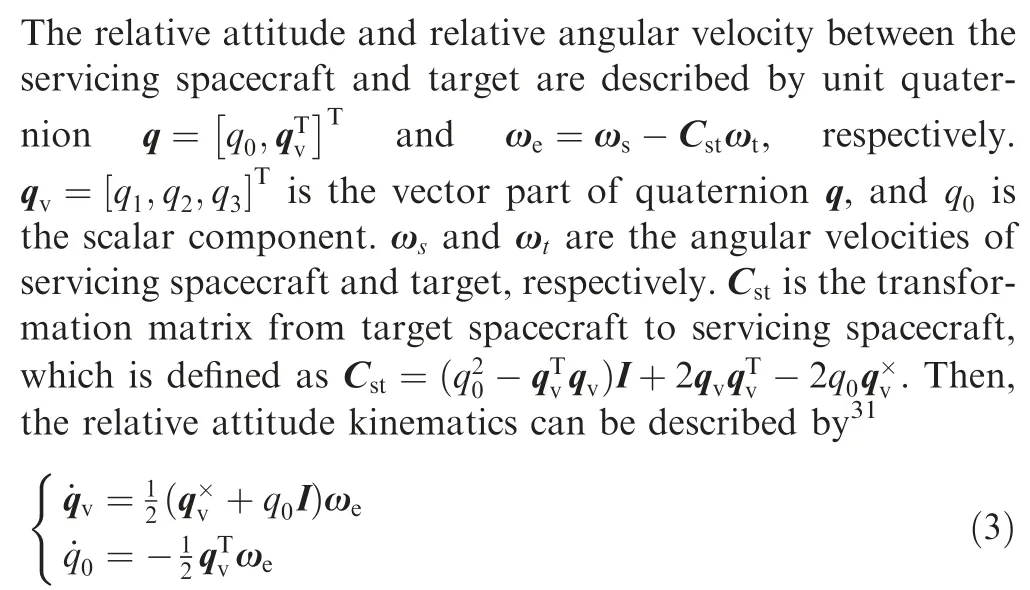
The attitude dynamics of the servicing spacecraft and the tumbling target are written as

where Js=Js0+ΔJsstands for the inertia matrix of servicing spacecraft,Js0and ΔJsare the known and uncertain portions of inertia matrix,respectively.Fris the coupling coefficient matrix between the servicing spacecraft rotation and flexible appendage vibration.Tcis the control torque generated by actuators,and Tdrepresents the environment disturbance torque.Jtis the unknown inertia matrix of the target.
Differentiating ωeachieves

By substituting Eq.(4) into Eq.(5),the relative attitude dynamics of servicing spacecraft can be derived as

The dynamic of the modal coordinate can be formulated as

where 2ζΩ and Ω2are the damping matrix and stiffness matrix,respectively.
2.3.Relative position and attitude dynamics

where the matrices and vectors are given as

Remark 1.Compared with the tracking control problem of cooperative target,the high-precision position and attitude tracking for tumbling non-cooperative target is more challenging.Firstly,the non-cooperative target has unknown inertia matrix Jt,which will bring unknown nonlinearity (e.g.,the term Γ) in dynamic model (8).Secondly,the tracking of tumbling non-cooperative target poses high requirement for the maneuver capability of servicing spacecraft.However,during the maneuver process,the coupling exists in the position and attitude dynamics due to flexible vibration induced by the rapid maneuver.Take the position dynamic for example,it can be seen from model (8) that the termsandare the coupling effects on the position dynamic due to attitude motion.Moreover,the mass and inertia variations of servicing spacecraft are inevitable as a result of fuel consumption and liquid sloshing.Meanwhile,the flexible vibration will in turn disturb the rigid hub of spacecraft via rigid-flexible coupling effect.These disturbances and uncertainties will severely deteriorate the control performances of position and attitude tracking.
Remark 2.In the position and attitude tracking process,multiple disturbances including parametric uncertainty,flexible vibration,unknown nonlinearity,and environment disturbance exist inevitably.These disturbances have different physical sources and exhibit different characteristics.More specifically,in the position and attitude dynamics,the mass and inertia uncertainties are coupled with the unknown linear acceleration and angular acceleration,respectively.The flexible vibration disturbance has partially known information (e.g.,stiffness and damping matrices).20According to the disturbance characteristics,the disturbances can be classified into three types: the mass and inertia uncertainties,the flexible vibration disturbance d0,and the other disturbance d1including unknown nonlinearity and environment disturbance.
2.4.Refined disturbance description
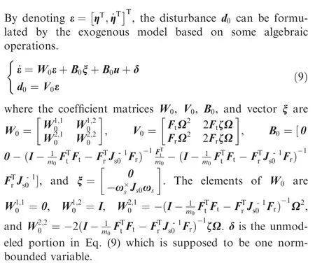
From the viewpoint of practical engineering,the mass and inertia uncertainties are norm-bounded.Hence,the neutral uncertainty termis bounded,where the boundary is related to2.Meanwhile,similar to the ADRC framework,the unknown nonlinearity and external environment disturbance generally have complicated dynamics,which can be lumped as one derivative-bounded variable.13Thus,‖‖<D1holds,whereD1is an unknown positive constant.
Remark 3.The six degrees of freedom dynamic models with multiple disturbances are established for the servicing spacecraft.Different from the traditional model,not only the position and attitude dynamics(8),but also the refined disturbance descriptions are given in this work.By fully analyzing and utilizing the disturbance information,the multiple disturbances are characterized by multiple mathematical forms: neutral uncertainty,exogenous model,and derivative-bounded variable.Compared with the traditional anti-disturbance control methods (e.g.,variable structure control,9,10ADRC,13and H∞control20) where only one type of disturbance is considered,the conservativeness has been reduced greatly in disturbance description.
3.Composite anti-disturbance control
As shown in Fig.1,a novel composite anti-disturbance controller with‘‘feedforward plus feedback”hierarchical structure is designed,where a dual DOBC is designed in the inner loop(feedforward channel) to compensate the disturbances with exogenous model and bounded derivative,and a sliding mode controller in the outer loop(feedback channel)is developed to attenuate the disturbance estimation errors and the neutral uncertainty caused by mass and inertia variations.
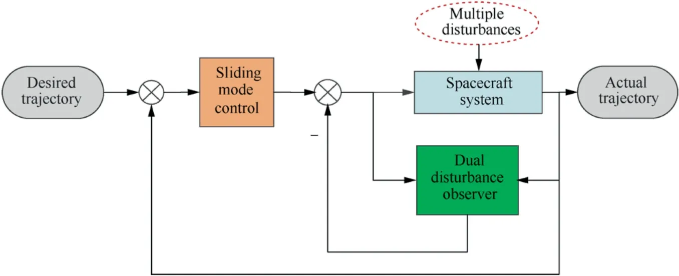
Fig.1 Structure of the proposed composite controller.
3.1.Sliding mode manifold
Design a sliding mode manifold as

with Υ=diag{Υ1,Υ2},where Υ1and Υ2are positive definite diagonal matrices.
Then,we can get the following equation with sliding mode manifold:

Next,a kind of dual disturbance observers will be proposed to estimate d0andin Eq.(11).
3.2.Dual DOBC design
For the flexible vibration disturbance d0,an exogenous modelbased disturbance observer is designed as
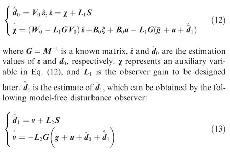
Similarly,the variable ν denotes an auxiliary variable in Eq.(13),and L2is the observer gain to be given later.
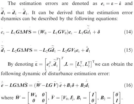
Remark 4.In the traditional disturbance estimation methods(e.g.,ESO),the disturbances are generally lumped as one differentiable variable,which is intuitive and effective when the disturbances have uncertain dynamics in practical engineering.However,many disturbances have more detailed information knownin priori.20,25According to the disturbance mathematical descriptions and classifications,the dual disturbance observers including Eq.(12)and Eq.(13)are designed.More specifically,the flexible vibration disturbance d0is estimated via the exogenous model-based disturbance observer(12)by utilizing the disturbance information,namely,the stiffness and damping matrices.The disturbancewith bounded derivative is estimated by the model-free disturbance observer(13).Compared with the traditional disturbance estimation methods,the disturbance information of multiple disturbances is fully used to accomplish more precise disturbance estimation.
3.3.Composite control
For system (11),the composite controller is proposed as

wherek0<0 andk1<0 are the controller gains.Then we can get

Remark 5.A composite anti-disturbance controller with simultaneous disturbance attenuation and compensation capabilities is proposed.However,it can be seen from Eq.(19)that the dynamics of sliding mode manifold and disturbance estimation error are highly coupled.Thus,it is no longer applicable to determine the gains of the sliding mode manifold and the dual disturbance observers separately.Hence,a unified stability analysis method is given by simultaneously considering the dynamics of sliding mode manifold and disturbance estimation error.
Remark 6.Different from the existing dual observers in Refs.29,30,the estimation errors of the proposed dual disturbance observers are affected by the neutral uncertaintydue to the mass and inertia variations.Meanwhile,the exogenous model error δ and the derivative ofexist in the estimation error dynamics.Therefore,a robust convex optimization method is adopted when solving the unknown gains.However,because the boundaries of δ andare unknown,the estimation accuracy qualification of the proposed dual disturbance observers is still lacking,which will be a research orientation in future work.Meanwhile,a more simple way to solve the observer gains needs to be further investigated.
Next,the stability of the augmented system which contains the dynamics of S andunder the proposed controller u will be analyzed.
3.4.Stability and robustness analysis
Theorem 1
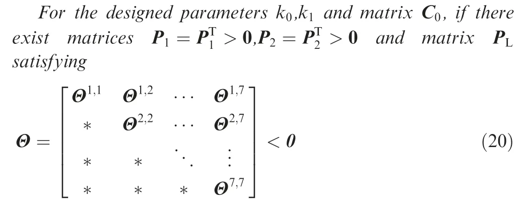
where the elements of Θ are given as
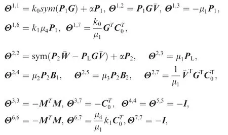
the rest elements in the upper right triangle of Θ are zeros,the symbol‘‘*”denotes the corresponding symmetric elements of Θ,α >0,μi>0 (i=1,2,...,4) are given constants.Consequently,both system (19) and system (8) are Uniformly Ultimately Bounded (UUB) stable by selecting the observer gain
Proof.The Lyapunov functions are selected as follows:

DifferentiatingV1andV2with respect time,then we can get
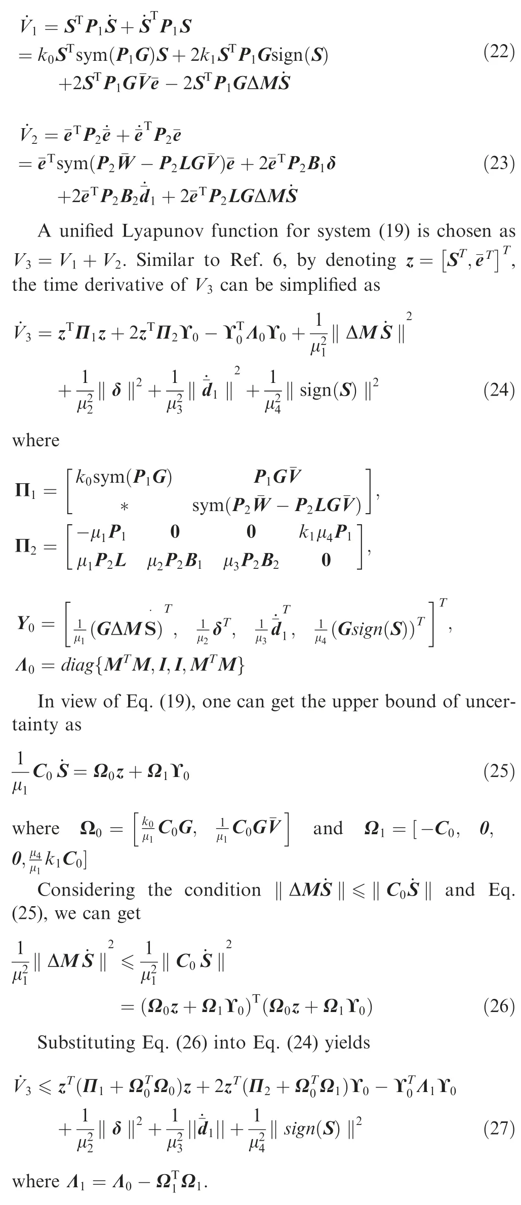
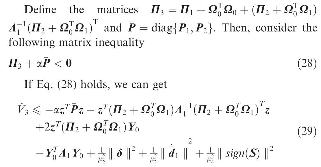
Based on some algebraic operation,Eq.(29)can be further transformed into
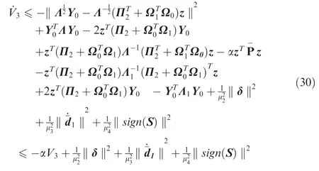
Hence,system (19) is UUB if Eq.(28) holds.It can be verified that Eq.(28) is equivalent to the following matrix inequality:

The matrix inequality Π4<0 can be rewritten as Θ <0 in Theorem 1.Therefore,the boundedness of S andhas been proven.Next,the dynamics in the sliding phase will be analyzed.The sliding mode manifold can be decoupled as

Consider a Lyapunov function as

Computing the time derivative ofV4and considering Eq.(3) yields
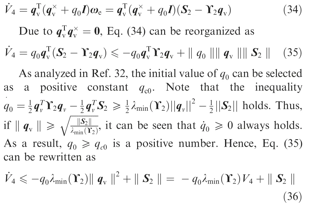
From Eq.(36),it can be concluded that qvis UUB because S is bounded,and qvwill converge into the bounded set‖qv‖≤asymptotically.According to Eq.(32),ωeis also UUB.In a similar manner,the UUB stability of reand vecan be analyzed.This completes the proof.
4.Numerical simulation
In this section,the control performances of proposed method are verified via numerical simulation.The proposed method is applied to the position and attitude tracking control of spacecraft.For the flexible vibration,the low-frequency modes generally have dominant influence.Therefore,only the lowest bending mode is considered for the servicing spacecraft.The simulation parameters are chosen in Table 1.

Table 1 Simulation parameters of spacecraft.
The initial values of re,qvandq0are re(0)=[10,-10,0]T,qv(0)=[0.1,-0.1,0]Tandq0(0)=0.9899,respectively.The initial values of veand ωeare zeros.The controller gains are selected ask0=-200,k1=-100,and the sliding mode manifold parameter Υ is chosen as an identity matrix.By solving the linear matrix inequality in Theorem 1,one group of feasible observer gains L1and L2are given as
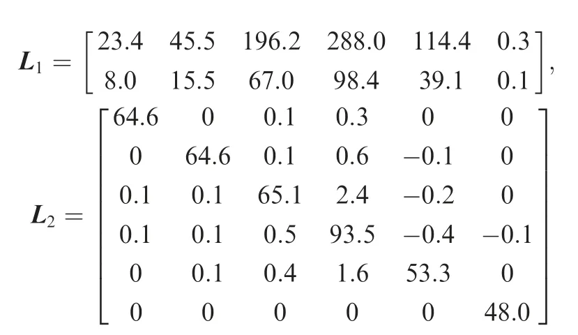
The performances of the proposed dual disturbance observers are verified via Figs.2–4.Fig.2 illustrates the actual disturbances (including d0and ¯d1) and the disturbance estimates both in the position channel and attitude channel,from which one can see that the actual disturbances can be tracked precisely and rapidly under the proposed dual disturbance observers.Moreover,the estimation performance comparisons are conducted between the proposed dual disturbance observers and the well-known linear ESO in ADRC.33,34The parameters of ESO are selected via the bandwidth optimization proposed in Ref.33.Fig.3 and Fig.4 give the comparison results in position channel and attitude channel of servicing spacecraft,respectively.As shown in Figs.3-4,no matter in the position channel or attitude channel,the proposed dual disturbances have much higher estimation accuracy than the ESO due to the usage of disturbance information,namely,the damping and stiffness matrices of flexible vibration.
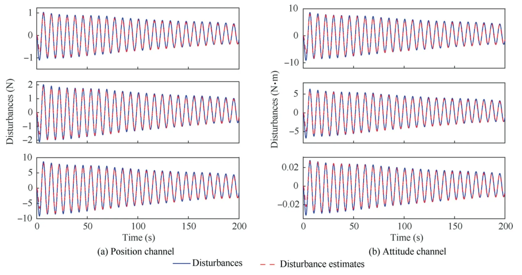
Fig.2 Estimation performance of dual disturbance observers.

Fig.3 Performance comparisons of different observers in position channel.

Fig.4 Performance comparisons of different observers in attitude channel.
The simulation curves of the relative position and relative attitude tracking errors of the servicing spacecraft are shown in Figs.5-6.Especially,to clearly verify the effectiveness of the composite controller,detailed comparisons are carried out between the proposed composite controller and the ADRC with an ESO plus PD structure in Ref.33.The relative position tracking errors under the proposed method and the ADRC are shown in Fig.5.It can be observed that both the two methods can drive the positions to the equilibrium points within roughly 80s.However,the position accuracy under the proposed method has been improved significantly,as compared to the ADRC method.Similar conclusions can be obtained in the attitude control channel,as illustrated in Fig.6.Hence,the proposed method can achieve high-precision position and attitude control by the refined disturbance estimation and compensation.
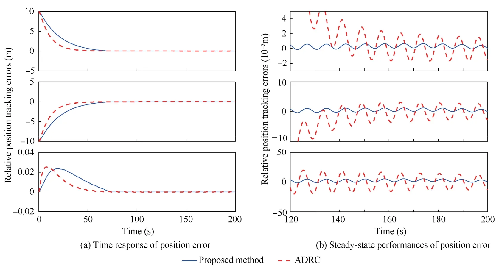
Fig.5 Position error comparisons under different controllers.
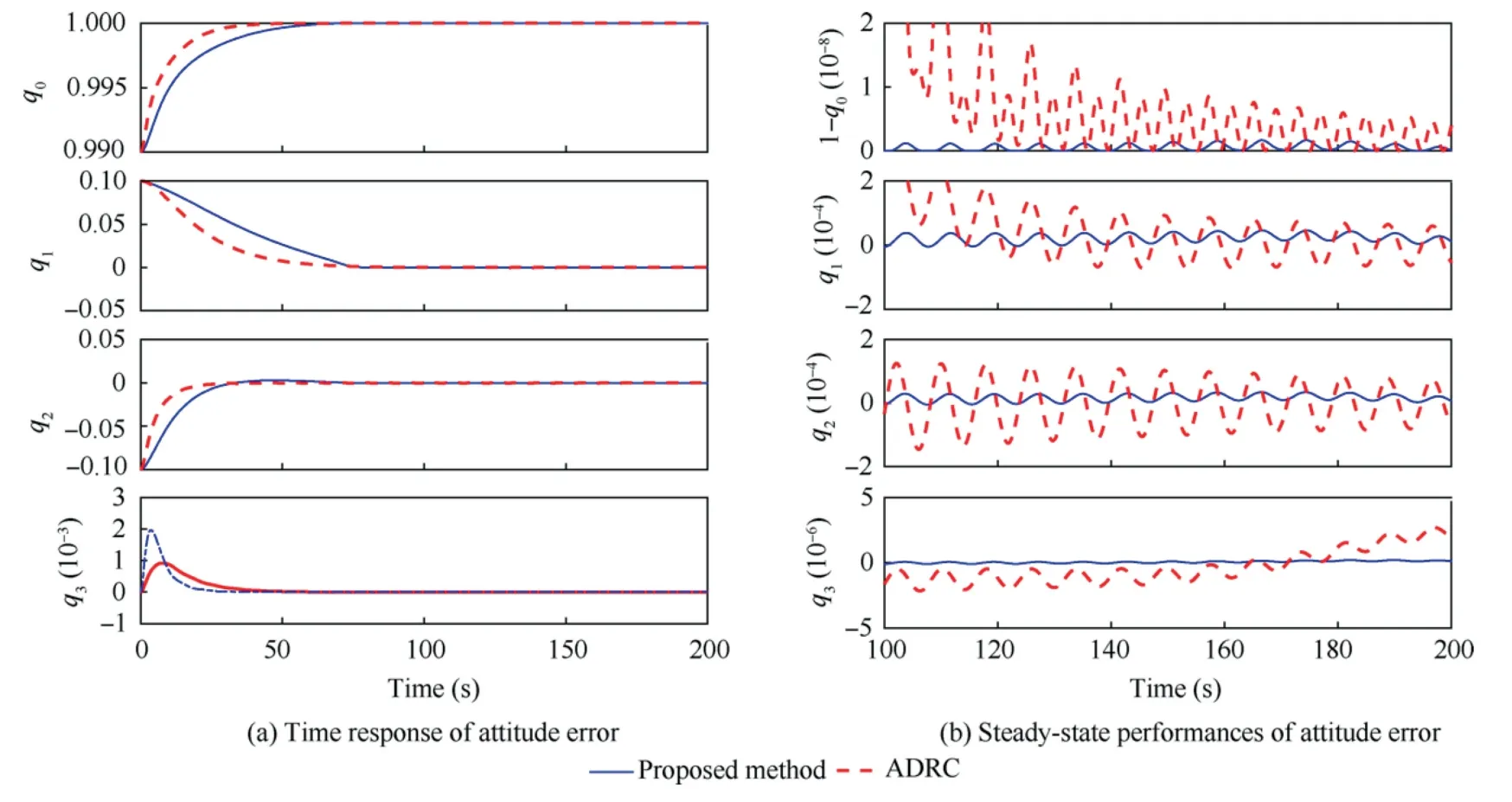
Fig.6 Attitude error comparisons under different controllers.
According to the above simulation results,it can be concluded that the composite controller is capable of compensating and attenuating the disturbances and uncertainties.The tracking precision and anti-disturbance capability of the spacecraft can be improved under the proposed composite antidisturbance controller.
5.Experiment
5.1.Semi-physical experimental platform
To verify the effectiveness of the proposed method in the viewpoint of practical implementation,experimental studies are carried out by using the semi-physical experimental platform.The structure of the experimental system is given in Fig.7.The experiment platform consists of star sensor,relative measurement sensor simulator,dynamic simulation system,control computer,actuator simulator,and some other soft or hardware modules.
The star sensor is used to measure the absolute attitude of the servicing spacecraft with regard to the inertial coordinate frame.The relative measurement sensor simulator is used to obtain the relative position and attitude information between the servicing spacecraft and the target.The control computer is used to collect the measurement data of each sensor and generates the control commands.Then the actuator simulator sends control force and torque to the dynamics simulation system according to the control commands.The dynamics simulation system receives signal from the actuator simulator and carries out simulation calculations of spacecraft position and attitude dynamics.The experiment system is also equipped with a monitoring computer to receive and display the data from control computer and dynamics simulation system.
5.2.Experiment results
The detailed experiment parameters are listed in Table 1.The initial conditions,observer gains,and controller gains are consistent with the simulation section.The experimental results under the proposed composite anti-disturbance controller are shown in Figs.8–9,where the relative position tracking errors and the relative attitude errors of servicing spacecraft with respect to target spacecraft are given,respectively.It can be seen from Fig.8 that the position errors of three axes can be driven to the neighborhoods of zeros within 80s,and the steady-state errors are less than 0.005 m.Similarly,it can be seen from Fig.9 that the attitude tracking errors can also be driven to the equilibrium points,and the vector parts of quaternion in the steady state are less than 0.0002.The experimental results have demonstrated that the proposed controller is effective in achieving the high-precision position and attitude tracking.
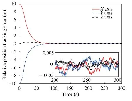
Fig.8 Time response of relative position error.
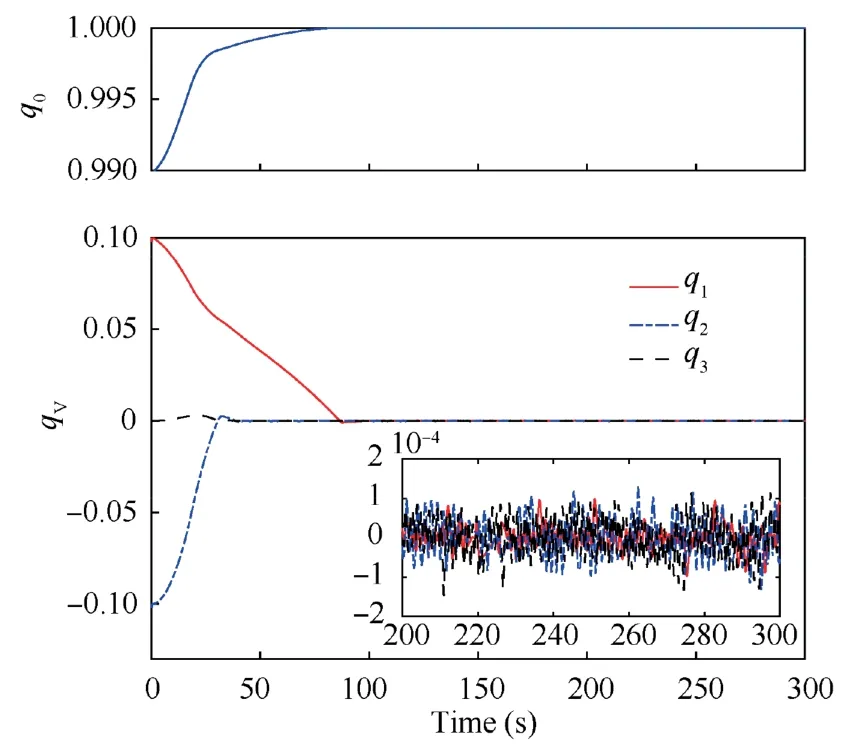
Fig.9 Time response of relative attitude error.
Moreover,the experiment results and the simulation results are compared to show their consistency.It can be concluded from Fig.8 that the position transient trajectories of experiment are close to that of the numerical simulation in Fig.5.The position steady-state accuracy of experiment is less than numerical simulation as a result of sensor noises,sampling delay,and some other errors in practical semi-physical experiment.Similar conclusions can also be obtained by comparing the attitude control results in Fig.6 and Fig.9.
6.Conclusions
For the proximity process with respect to a tumbling noncooperative target,this paper proposes a novel composite anti-disturbance control law for the spacecraft position and attitude of in the presence of parametric uncertainty and flexible vibration.The relative position and attitude dynamic models of the servicing spacecraft are established,where not only the position and attitude dynamic models,but also the refined disturbance descriptions are presented based on their characteristics.Then,a hierarchical-architecture composite controller by combining a dual DOBC and a slide mode control is proposed,where the disturbances and uncertainties can be attenuated and compensated simultaneously.Numerical simulations and experiments studies have demonstrated that the proposed composite control law can exhibit higher control precision and better anti-disturbance capability.
Declaration of Competing Interest
The authors declare that they have no known competing financial interests or personal relationships that could have appeared to influence the work reported in this paper.
Acknowledgements
This work was supported by the China National Postdoctoral Program for Innovative Talents(No.BX20200031),the National Natural Science Foundation of China(Nos.62103013,61633003,61973012),and the Program for Changjiang Scholars and Innovative Research Team,China(No.IRT 16R03).
 CHINESE JOURNAL OF AERONAUTICS2022年12期
- CHINESE JOURNAL OF AERONAUTICS的其它文章
- Control and utilization of range-dependent beampattern with waveform diverse array radars
- Airside pressure drop characteristics of three analogous serpentine tube heat exchangers considering heat transfer for aero-engine cooling
- Numerical analysis of deflection control of a gas plasma jet based on magnetohydrodynamic staggered electrode configuration
- Neural network-based model predictive control with fuzzy-SQP optimization for direct thrust control of turbofan engine
- Method for utilizing PIV to investigate high curvature and acceleration boundary layer flows around the compressor blade leading edge
- Experimental investigation of expansion effect on shock wave boundary layer interaction near a compression ramp
