Maneuver control at high angle of attack based on real-time optimization of integrated aero-propulsion
Juan FANG,Qiangang ZHENG,Changpeng CAI,Haibo ZHANG
College of Energy and Power Engineering,Nanjing University of Aeronautics and Astronautics,Nanjing 210016,China
KEYWORDS High angle of attack;Inlet/engine integration;Real-time optimization;Engine performance;Auxiliary intake valve
Abstract To reduce the propulsion system installation thrust loss under high angle of attack maneuvering,a control method based on real-time optimization of the integrated aeropropulsion is proposed.Firstly,based on data fitting and physical principle,an integrated onboard model of propulsion system is established,which can calculate various performance parameters of the propulsion system in real time,and has high accuracy and real-time performance.Secondly,to improve the compatibility of optimization real-time performance and search accuracy,the online optimization control of aero-propulsion system is realized based on an improved trust region algorithm.Finally,by controlling the auxiliary intake valve,a good match between inlet and engine is realized,which solves the problems of intake flow reducing and total pressure recovery coefficient declining,and improves the installation performance of propulsion system.The simulation results indicate that,compared with the conventional independent engine control,the real-time integrated optimization method reduces the installed thrust loss by 3.61% under the design condition,and 4.58% under the off-design condition.Furthermore,the simulation on HIL (Hardware-In-the-Loop) platform verifies the real-time performance of integrated optimization method.
1.Introduction
With the development of modern combat aircraft,increasing attention is attached to aircraft maneuverability.To improve the ability of fight,the past-stall flight is essential to jet fighter,which means flight at high angle of attack.1,2The large-scale separation of the flow field at this situation leads to problems such as insufficient air intake,excessive overflow resistance,and uneven flow field,which reduce the installed thrust and even cause fan surge.3,4Besides,the total pressure distortion at inlet exit also has impact on the stability of the engine.For the stability and safety of maneuvering at high angle of attack,the design objective of conventional controller is to remain sufficient safety margin under the worst flight condition.As a result,propulsion system is unable to give full play to its performance under off-design condition.
In response to such problems encountered by aircraft at high angles of attack,NASA implemented the High Stability Engine Control (HISTEC) research program5–8at the end of the 20th century.In this program,a strategy is proposed,and by estimating the distortion of engine inlet,correction command is obtained and exported to Stability Management Control(SMC)system.And decision is made in the SMC system based on the control logic,which keeps the engine away from the surge boundary by controlling the area of nozzle.On this basis,Refs.9–12proposed a method of adjusting engine fuel and nozzle area by estimating the engine surge margin online to remain surge margin within a small range of fluctuations.Despite the partly improved performance of the propulsion system,those methods ignore the coupling effect between the supersonic inlet and the engine.In the 20th century,NASA launched the High Alpha Technology Program (HATP).4Its research goal is to obtain high inlet performance at low subsonic speed and high angle of attack.The flight result indicates that the auxiliary intake valve can effectively improve the performance of the propulsion system at high angle of attack.Since then,some scholars have studied the influence of the auxiliary intake valve on the propulsion system13–15and the aerodynamic characteristic of maneuvering at high angle of attack by adopting the CFD simulation16,17,but failed to provide a solution to the instability of the propulsion system at a high angle of attack.Although there are abundant achievements in research of supersonic inlet and auxiliary intake valve,the current research on the integrated control of inlet and engine under high angle of attack flight is insufficient,and few achievement is obtained.In Ref.18,PID controller is utilized to adjust the auxiliary intake valve andH∞method is adopted to control the rotor speed to maintain high total pressure recovery coefficient.This method improves the performance of the propulsion system when the angle of attack is 60°,by which the installed thrust is increased by 16% and the fuel consumption rate is reduced by 6%.The result shows that the integration control of the propulsion system is effective to improve the installation performance at high angle of attack.Unfortunately,this offline design method is unable to track the propulsion system state,and adjust the control logic in time when external and internal condition change.The auxiliary bleed valve and ramp are chosen as the optimization control variables in Refs.19,20,and the SQP/FSQP (Sequential Quadratic Programming/Feasible Sequential Quadratic Programming) algorithm is adopted to calculate the optimal parameter online.Those methods improve the installation performance in the supersonic cruise state by adjusting the matching performance of inlet and engine.The methods have a certain reference significance,but the flight status studied is different from this paper,and the real-time performance of the component-level model and algorithms utilized in the references is inferior,which makes it difficult to apply to practical engineering.Hence,it is essential to further study the integrated control at high angle of attack.
For this reason,this paper proposes an angle of attack maneuver control method based on real-time optimization of the integrated aero-propulsion,which improves the installation performance of the propulsion system in this situation.First,the research on the supersonic inlet and its characteristics during maneuvering at high angle of attack is carried out.The auxiliary intake valve model is established using CFD software,and its influence on the performance of the propulsion system is explored.Then,the method of data fitting and physical principle are utilized to build an on-board engine model,and an integrated model of the propulsion system is built based on the flow balance equation of the inlet and the engine.Finally,on this basis,an improved trust region algorithm with superior real-time performance is adopted to optimize the auxiliary intake valve angle online,which improves the installation performance of the propulsion system during maneuvering at high angle of attack.
2.Principle of supersonic inlet
As the main intake device of the propulsion system,the supersonic inlet has a vital influence on engine.The ideal inlet should provide the engine with a uniform pressure field and speed field,can be self-adjusted according to the actual demand flow of the engine,and has the least external resistance.However,the actual supersonic inlet will produce greater overflow resistance when the flying Mach number is bigger than the design Mach number.When the required flow rate of inlet is beyond the maximum flow rate,the total pressure recovery coefficient will decrease,which results in a decrease in the performance of engine.When the aircraft is maneuvering at a high angle of attack,due to the influence of the intake angle,the air flow provided by inlet to the engine is drastically reduced,resulting in a significant drop in engine thrust,and even causing the aircraft to enter a stall or spin state.Therefore,the characteristics of the supersonic inlet,the influence of the high angle of attack on the supersonic inlet,and the adjustment method of the supersonic inlet will be introduced,and the reasons and adjustment principle that affect the performance of the supersonic inlet will be explored in this section.
2.1.Characteristic of supersonic inlet
Throttling characteristic and speed characteristic are the main characteristics of supersonic inlet.Throttle characteristic refers to the relationship between the performance parameters of inlet and the air flow through the engine under a certain flying Mach number.Fig.1(a) shows the throttle characteristic diagram of the non-adjustable external pressure inlet.The speed characteristic refers to the relationship between the inlet performance parameters and flying Mach number,as shown in Fig.1(b).σ is the total pressure recovery coefficient,and φ is the flow coefficient.Mais the flying Mach number,andMadis the design Mach number.q(λ)is the flow aerodynamic function.
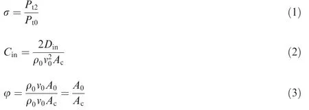
The performance parameters of the inlet include the total pressure recovery coefficient σ,the resistance coefficientCin,and the flow coefficient φ.The total pressure recovery coefficient is the ratio of the total pressurePt2at the outlet of inlet to the total pressurePt0of the undisturbed cross-sectional air flow in front of inlet.The resistance coefficient is the ratio of the total external resistance of inletDinto the dynamic pressure of the undisturbed air flow,and the flow coefficient is the ratio of the mass flow of air actually entering inlet to the maximum possible flow.ρ0andv0are the air density and velocity of inlet entrance respectively.A0andAcare the air inflow area of inlet entrance and geometric area of inlet.The mathematical expressions are shown in Eq.(1)-Eq.(3).
The structure of the supersonic inlet in this paper is shown in Fig.2.The shocks series consist of three oblique shock waves and a normal shock wave.The quality of the airflow that inlet provide to engine changes with the position of shock wave.

Fig.2 Schematic diagram of supersonic inlet.
As shown in Fig.1(a),at a certain Mach number,the air flow through the engine changes with the working state of the engine.When working at design state,the shock waves lie at the lip of inlet.The oncoming air flow is exactly equal to the flow required by the engine,and the similar flow of the air flow at the exit section of inlet is also equal to the similar flow obtained by the compressor inlet section.At this time,the total pressure loss is relatively small.When the engine demand flow increases,the flow rate that inlet can provide is unable to increase.In order to increase the similar flow rate,the airflow begins to expand and accelerate after the oblique shock wave,passes through a stronger position shock,and turns into subsonic airflow.As a result,the total pressure recovery coefficient decreases.When the engine demand flow rate is less than the flow rate of the critical state of the inlet,part of the air flow overflows from the lip,resulting in greater overflow resistance.
As shown in Fig.1(b),whenMa<Mad,part of the airflow flows out of the inlet,which brings additional resistance,resulting in the increase of the drag coefficient.WhenMa>Mad,the total pressure recovery coefficient decreases.The generation of additional resistance obviously reduces the installation performance of the propulsion system (such as installation thrust),and the reduction of σ also leads to a decrease in the airflow pressure at the engine entrance,which in turn causes a proportional reduction in the air flow through the engine,and ultimately leads to the decrease of gas exhaust speed,so the thrust reduces.
2.2.Effect of high angle of attack
When maneuvering at a high angle of attack,there is a largescale flow separation phenomenon around the aircraft.21The static pressure difference roused by flow separation results in a distortion of the total inlet pressure,which has tremendous impact on the stability of the engine,and generally causes the stability boundary of components to move downward.Fig.3 is the stability boundary of compressor under the conditions of no distortion,90°and 150°circumferential distortions.θciris the circumferential distortion angle,Nfis the low pressure rotor speed.The stability boundary moves down with the increase of circumferential total pressure distortion.And it is the main reason for the reduction of the engine stability margin.The main performance parameters such as compressor pressure,efficiency and flow rate under the condition of total pressure distortion will change because of distortion.This change is usually an upward movement of the working line,but the magnitude of the change is small compared with that of the stable boundary.
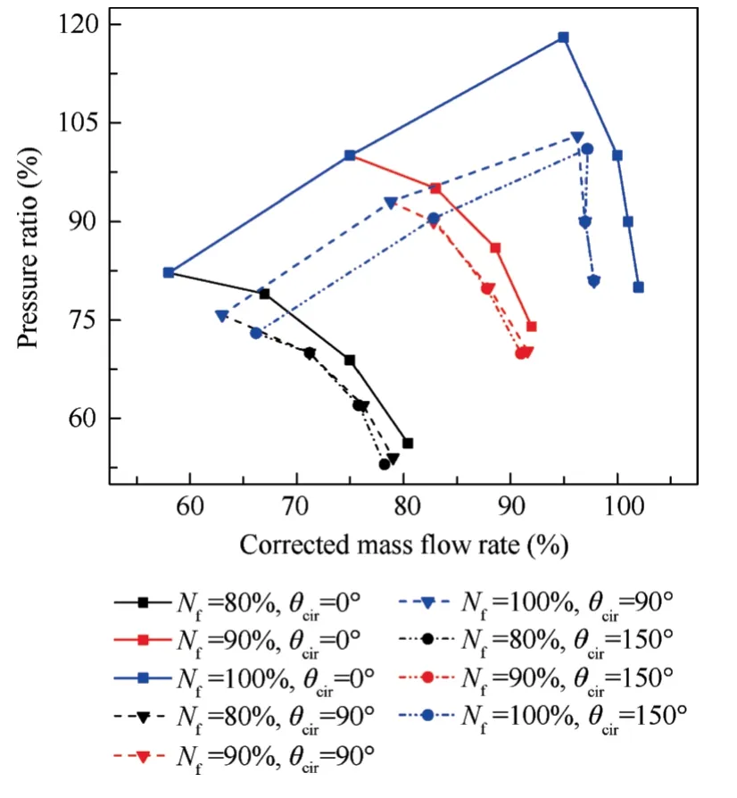
Fig.3 Influence of circumferential distortion angle on stability boundary.
The total pressure distortion of the inlet affects the characteristic parameters of fan such as flow rate,pressure ratio,efficiency,etc.Thus,the original characteristic line is not suitable for the distorted engine model.It is necessary to obtain characteristic data under a specific distortion index through experiments,and obtain a new characteristic line by interpolating.Fig.4 is the characteristic line of fan pressure ratio,efficiency and corrected flow rate.The solid lines indicate the condition without distortion and the dotted lines indicate the condition that distortion index isD-=0.2.
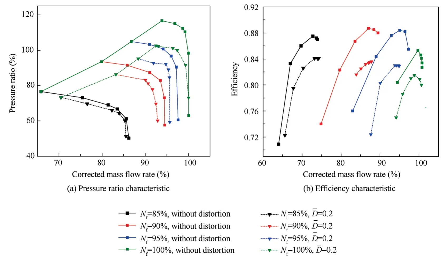
Fig.4 Fan characteristic under total pressure distortion.
2.3.Auxiliary intake valve
The auxiliary intake valve is an important adjustment method of the supersonic inlet,which is mainly used for low-speed flight and large maneuvering flight conditions of the aircraft.On one hand,the auxiliary intake valve supplements the intake air,which increases the outlet flow of the inlet and reduces the total pressure loss.On the other hand,it can reduce the angle of the low-speed airflow and reduce the flow velocity at the inlet,thereby alleviating the airflow separation loss and the uneven distribution of the inlet pressure caused by the shock loss.Its structure is shown in Fig.5.
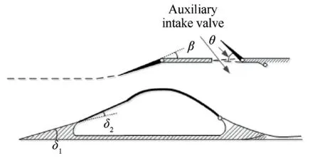
Fig.5 Structure of auxiliary intake value.
Based on the two-dimensional inlet CFD model,the influence of the auxiliary intake valve on inlet exit flow rate and the total pressure recovery coefficient is simulated under different Mach numbers and angles of attack.The mesh of the inlet model is shown in Fig.6.When dividing the grid,the grid near the wall of the inlet and the grid near the auxiliary intake valve are encrypted to ensure the accuracy of the calculation.The number of grids in the inlet model is 195747,of which 97%of the grids have a quality of 0.998.The two-dimensional inlet simulation calculation is based on the CFD FLUENT software.Thek-ω SST (Shear Stress Transport) is selected as the turbulence model.The selected boundary conditions mainly include the far field boundary and the pressure outlet boundary.

Fig.6 CFD mesh of supersonic inlet with auxiliary intake valve.
The effects of the auxiliary intake valve and the angle of attack on the total pressure recovery coefficient and the inlet exit flow ratem2are shown in Fig.7.The flow ratem2has been normalized by the parameter at state θ=0°,α=0°,α is the angle of attack.When the auxiliary intake valve is closed,the total pressure recovery coefficient of the inlet is low,which is only 91.17%.With the increase of the angle of attack,the total pressure recovery coefficient and the outlet flow rate decrease constantly.As the opening degree increases,the total pressure recovery coefficient and the flow rate are significantly improved.When the opening degree is 40°,σ increases by 4.38%,and the flow rate increases by 3.572%.However,as the angle of attack changes,the best opening of the auxiliary inlet keeps changing.When the angle of attack reaches 60°,the best auxiliary intake valve opening degree is 20°.
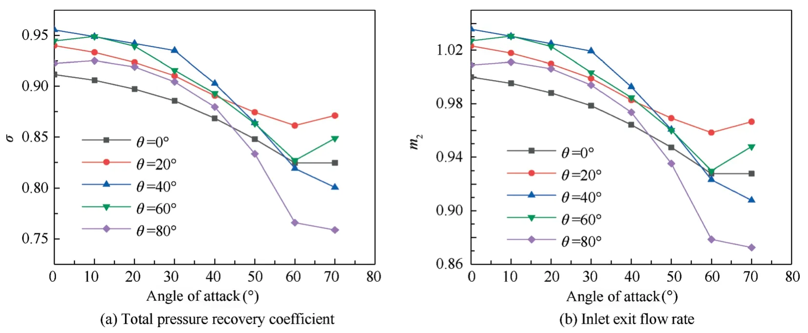
Fig.7 Effect of auxiliary intake valve and angle of attack.
3.Integrated onboard model of aero-propulsion system
By matching engine and inlet better,the performance of propulsion system can be improved at high angle of attack.Consequently,the research on the coupling characteristics of inlet and engine is of great significance.Furthermore,in order to achieve real-time integrated optimization,an integrated onboard model of propulsion system must be built.
3.1.Modeling of supersonic inlet
3.1.1.Internal flow characteristics
The inlet exit section parameters that are usually concerned mainly include temperatureTt2,pressurePt2,and corrected flowm2,c,which can be expressed as

whereT0andP0are the temperature and pressure of air flow at inlet entrance,which can be calculated according to altitude and Mach number.κ is the specific heat ratio of air flow.
The exit flowm2of inlet is shown in

whereA2is the area of the inlet exit section,λ2is the inlet exit velocity coefficient,q(λ2)is the flow function of the inlet exit section,andRis the gas constant.
The corrected flowm2,cat the inlet exit section is given as

where θc=T2/288.15,δc=P2/101325.
3.1.2.Outflow characteristics
Outflow characteristics mainly refer to the external resistance of the inlet,including overflow resistance and bleed resistance.The overflow resistance is introduced in detail as the focus of this paper is on the effect of auxiliary intake valve.According to Eq.(2),the calculation formula of inlet resistance is

The overflow resistance is mainly composed of additional resistance and the pressure drop of the inlet cover,which can be obtained by the overflow resistance coefficientCsp.The overflow resistance coefficient is related to the Mach number and the flow coefficient,which is unable to be derived directly from the formula.It is obtained by a large number of experiments.The characteristic diagram is shown in Fig.8.The overflow resistance coefficient increases with the decreasing flow coefficient.As the flow coefficient increases,the overflow coefficient gradually decreases,and finally drops to zero.
3.2.Modeling of turbofan engine
Based on the Compact Propulsion System Model(CPSM)22–24proposed by NASA,the Compact Propulsion System Dynamic Model (CPSDM) is built.As shown in Fig.9,the model is composed of a baseline model,a state-space variable model and a nonlinear sub-model.The baseline model represents the steady-state output of the core engine from the fan to the outlet of the mixing chamber without degradation,and the fan and compressor guide vane angles are at the design state;the state-space variable model reflects the dynamic performance of the engine;Sub-models including nozzle mode,surge margin model and afterburner model are used to calculate the parameters that are difficult to calculate by similarity conversion.

Fig.9 Structure of CPSDM.
3.2.1.Baseline model
In the traditional baseline model,similarity transformation ensures the feasibility of the model within the entire envelope.However,with the increase of ΔTt2=Tt2-(Tt2)H=0,Ma=0(His the height),the error of similarity conversion increases,resulting in a larger cumulative error of the baseline model,and ultimately leading to an increment of the CPSDM output error.Thus,eliminating the accumulated error caused by the increase is an important approach to ensure the accuracy of the baseline model.In this paper,K-means clustering25and Batch Normalized Deep Neural Network (BN-DNN)26,27are utilized to construct a baseline model suitable for the entire envelope.
To reflect the characteristics of different flight conditions in the baseline model,the relationship amongH,Maand engine parameters is discussed firstly.As known to all,the total temperature and pressure of inletTt1,Pt1entrance can be expressed as Eq.(9),which is related to Mach number.

And as shown,T0,P0indicate the flight height of engine.

Besides,Tt1,Pt1are also closely connected to the engine parameters as

Thus,Tt1,Pt1can be selected as the metric vector to divide the flight envelope,which reflects both the flight condition and engine entrance condition.

wherew1,w2are the weight,which arew1=0.5,w2=0.5 in the paper.
According to Eq.(12),the flight envelope is divided into 20 clustering intervals as shown in Fig.10 by K-means clustering method.The data of each cluster center is collected to reflect the engine characteristics of the interval.
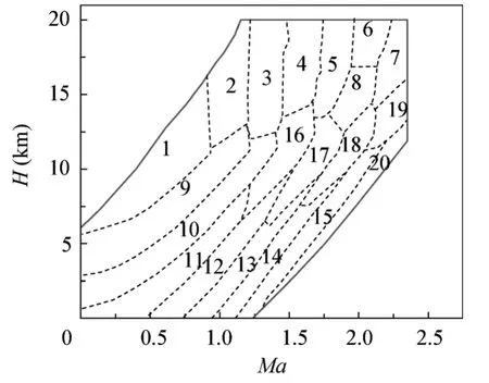
Fig.10 Flight envelope division using K-means clustering method.
TakingTt2as the input condition,the baseline model established by BN-DNN can be expressed as

wherefBN-DNNis the function of baseline model established by BN-DNN,u=[Wfb,A8]T,Wfbis the main fuel flow,A8is the nozzle throat area,andTt2is the total temperature of fan entrance.Y0=[Pt65,Nf,Nc,Tt25,Pt25,Pt3,Tt4,Tt65,ma25,mg65],the subscript ‘‘0” indicates the output parameters of baseline model,Pt65is the total pressure of mixer exit,Nfis the low pressure rotor speed,Ncis the high pressure rotor speed,Tt25,Pt25are the total temperature and pressure of fan exit,Pt3is the total pressure of compressor exit,Tt4is the total temperature of high-pressure turbine entrance,Tt65is the total temperature of mixer exit,ma25is the air flow of fan exit,andmg65is the gas flow of mixer exit.
BN-DNN is one kind of deep neural network,and its structure is exhibited in Fig.11,where the subscript‘‘cor”indicates the corrected value.In the training process of Deep Neural Network (DNN),the change of data distribution of internal nodes caused by the change of network parameters will lead to the decrease of network learning speed,and the training process is easy to fall into the gradient saturation area,and reduce the network convergence speed.In this paper,BNDNN is adopted to build the baseline model because of its advantages of fast convergence speed and high training accuracy.
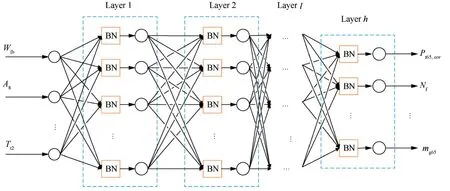
Fig.11 Improved baseline model based on BN-DNN.
The main difference between BN-DNN and DNN is the BN layer before each hidden layer.BN is a data preprocessing method,which divides the data intoNbatches withmgroups of data,and normalizes the data before each hidden layer.Assume that the input of hidden layer isxi(i=1,2,...,m),and then the normalization formulas are given as

where μBis the mean value of data,is the variance,ε is a small positive number to avoid division by zero andis the standardized output ofxi.
3.2.2.State-space variable model
An on-board dynamic model which can reflect the dynamic characteristics of the engine is obtained by adding the state space equation to the CPSM.The state space equation of the model can be expressed as


3.2.3.Nonlinear sub-model
Nonlinear sub-models are used to calculate components and parameters that are difficult to accurately calculate with similarity rules,including the nozzle model,surge margin model and afterburner model.The nonlinear model takes the output of the baseline model as the input condition,and calculates the output according to the physical principle.
(1) Afterburner model
Similar to the component level model,the afterburner is built according to the component characteristics and the corresponding balance equation.The physical principle is:

wherefabis the function of afterburner,Wfais afterburner fuel,Tt7,Pt7are the total temperature and pressure of afterburner exit respectively,andmg7is the gas flow of afterburner exit.
(2) Surge margin model
The surge margin of fans and compressors depends on their characteristic curves and the positions on the characteristic curves.Taking the fan as an example,the position of the common operating point of the fan can be determined through the pressure ratio and the corrected rotor speed.And the characteristic curve is related with the change of the guide vane angle and the degradation of the fan characteristics.Therefore,the fan surge margin can be expressed as

whereis the function of surge margin of fan,αfis the guide vane angle of fan.
Similarly,the calculation formula of the compressor is:

whereis the function of surge margin of compressor,αcis the guide vane angle of compressor.
(3) Nozzle model
The nozzle model is built to calculate engine thrustFand specific fuel consumption SFC by the pressure,flow and temperature at the outlet of the afterburner,which can be expressed as

wherefNis the function of nozzle,A9is the area of nozzle exit.
3.3.Integrated propulsion system model
The working state of inlet is determined by the entrance condition and intake flow.When the entrance condition and the mechanical position of inlet are fixed,the total pressure recovery coefficient is determined.And the pressure of inlet exit is related to the total pressure recovery coefficient.The relationship among inlet parameters can be expressed as

wherefIis the function of inlet,fEis the function of engine,m21is the air flow of fan entrance,Pt21is the total pressure of fan entrance.
For engine,Pt21is the input condition and not affected by other parameters.Besides,Pt21affects the demand flow of engine.When the pressure of engine is equal to inlet exit pressurePt2,the corrected flow of engine and inlet are expected to be equal,as shown in

The principle of integrated modeling is shown in Fig.12.Flight height,Mach number,flow coefficient,θ and α are the input parameters of inlet,and the initial state of the flow coefficient is 1.At this time,the temperature and pressurePt2,Tt2at the outlet can be calculated by the inlet model,which are transferred to engine model.With fuel flow and nozzle area,the current required corrected air flowm21,cof engine can be calculated.According to the flow balance Eq.(22),Newton-Raphson28is adopted to solve the flow coefficient φ satisfying εm=m2,c-m21,c<10-5,where εmis the flow residual.
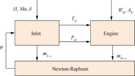
Fig.12 Principle of integrated model.
4.Optimization problem and algorithm
To solve the problem of insufficient performance of the propulsion system under high angle of attack,an integrated optimization control research is carried out.The control structure29shown in the red dashed box in Fig.13 is adopted,whereP3is the static pressure of compressor exit.It includes a fan speed controller,acceleration controller,deceleration controller,and idle controller.Due to different targets,the constraints that each controller needs to meet are often different.Hence,to ensure the safe operation of the engine,a high-low selector is utilized to select the control variables that meet all the constraints.On this basis,the supersonic inlet controller is added,and the improved trust region algorithm is adopted to optimize the transition state performance of the propulsion system.Fefis the installation thrust of propulsion system.
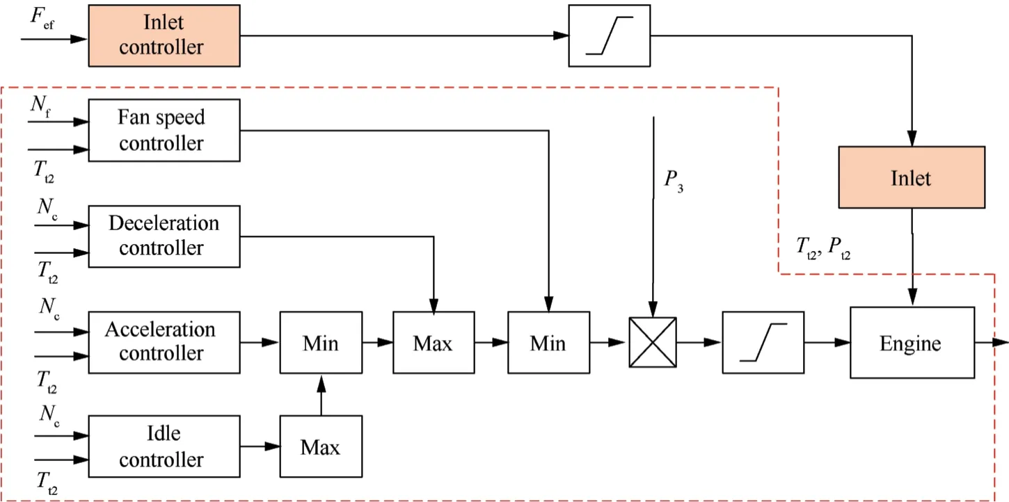
Fig.13 Schematic diagram of controller structure.
4.1.Math description
In the traditional engine performance optimization problem,parameters such as fuel flow and nozzle area of the engine are the main optimization parameters.This kind of optimization problem belongs to the steady-state optimization of the engine.Usually there are multiple optimization variables,and the computing time of single step is longer.Comparatively,the dynamic optimization requires that there must be a calculation result in each simulation step,otherwise the calculated result will no longer be suitable for the current state point.So the real-time performance is a core issue of dynamic online optimization.In order to meet the real-time demand of the dynamic optimization process,auxiliary intake valve is selected as the only optimization parameter,and the main idea of improving the installation performance of the propulsion system in the high angle of attack maneuvering flight state is to match engine and inlet better in the process.
The optimization objective function and constraint conditions of the entire dynamic process can be described as
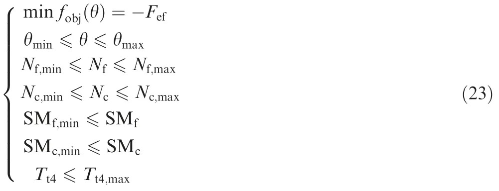
wherefobjis the objective function of optimization.
Converting the constraint condition of the engine into the constraint function is shown in Eq.(24),which needs to be satisfied in the optimization process.
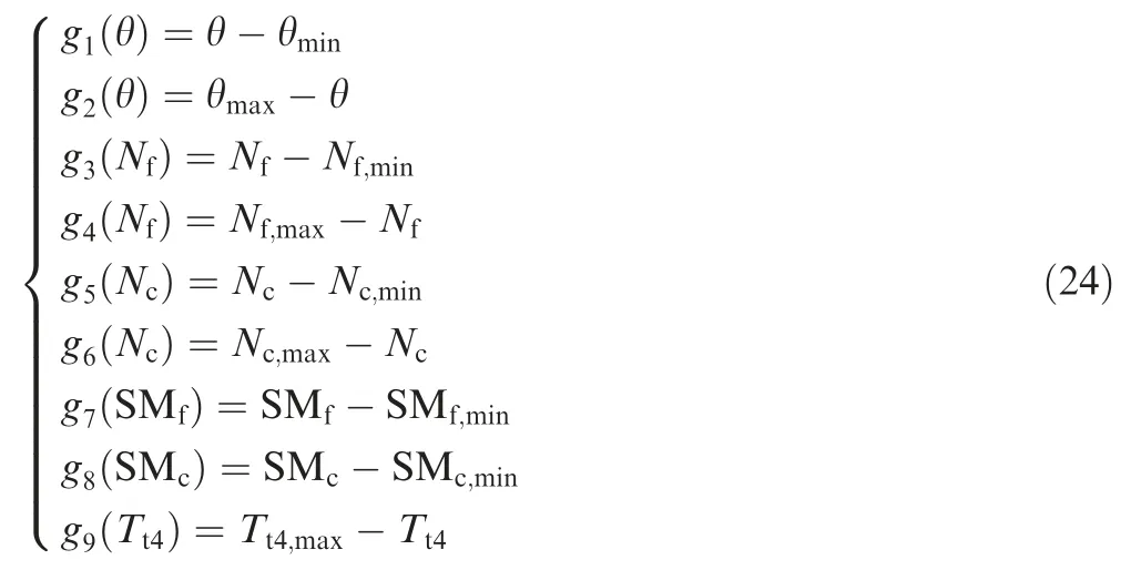
Finally,Eq.(23) can be written as

4.2.Trust region algorithm
Trust region algorithm has the advantages of strong convergence and reliability,and has become a hot research topic for solving nonlinear programming problems30,31.The core idea of the trust region method is that in the neighborhood of the current iteration point xk,a model functionmk(dk)is utilized to approximate the original objective functionf(xk+dk),and minimize the functionmk(dk)in this neighborhood (solving sub-problems).Find the possible improvement value (trial step dk),and then determine whether this possible improvement point is accepted according to certain criteria.The size of the trust region radius is adjusted by iteration.If the current iterative model approximates the original problem superiorly,the trust region radius can be expanded,otherwise it is reduced.
In short,the basic idea of the trust region method is to remain the trial step dkto be within the trust region.That is,there is a positive number Δkin each iteration,so that the trial step dksatisfies‖dk‖≤Δk,where||||is a norm in Rn.The trial step dkof the trust region algorithm in a sense(for the approximation problem)makes xk+dkthe best point on the generalized sphere centered on xk.Because the increment xk+1-xkof the variable xkis supposed to satisfy ‖xk+1-xk‖≤Δk,a trust region algorithm can be constructed for any type of optimization problem.The steps are as follows:
Step 1.Set the initial value x0∈Rn,Δ0>0,k=1.
Step 2.Calculate a trial step satisfying ‖dk‖≤Δk.
Step 3.If dksatisfies the descending condition,then xk+1=xk+dk;otherwise,xk+1=xk.
Step 4.Calculate Δk+1and setk=k+1;go to Step 2.
In the process of implementing the trust region algorithm,the calculation of trial step is a significant step.It is usually obtained by solving a problem that is close to the original problem.This approximation problem is generally called as sub-problem.
For unconstrained optimization problems.

wheref(x):Rn→R is a second-order continuous differentiable function.
For the above unconstrained optimization problems,using quadratic approximation,the general form of the objective function dependent on the model is.

where dk=x-xk,gk=∇f(xk)∈Rn,Bk∈Rn×nis the Hessian matrix or its approximate matrix off(xk)at xk.
Hence,the trust region sub-problem is structured as follows:

where Δk>0 is the radius of the trust region,and ‖·‖ is the Euclid norm in Rn.Suppose the optimal solution of Eq.(28)is dk,and if Bk=∇2f(xk),then

In the process of realizing the trust region strategy,the simi larity betweenmk(dk)andf(xk+dk)is the basis for adjusting the radius of the trust region.Define parameters as

Generally,Predk>0.If γk<0,then Aredk<0,so xk+dkcannot be used as the next iteration point,and the trust region radius needs to be reduced and recalculated dk.if γk>0 and close to 1,it indicates that the quadratic function is close to the target function within the trust region,and the radius of the trust region is appropriately expanded at the next iteration.
4.3.Improved trust region algorithm
Since the dynamic process is continuous,if the traditional trust region algorithm is used for optimization,the principle is to find the optimal solution at each state point,as shown in Eq.(30).In each step,the second derivative and Hessian matrix are calculated,which increase the time consumption greatly.For the transient state control problem,the real-time requirement of the algorithm is pretty strictly restricted by the simulation environment.Thus,the traditional trust region algorithm cannot be applied to the problem directly.

where xkis the optimization parameters of engine at stepk,Fef,krepresents the installed thrust at stepk.The optimization parameter in the paper only includes auxiliary intake valve angle,but for the sake of generality,xkis taken as a vector.
In order to meet the real-time requirements,an improved trust region algorithm is adopted in this paper.In the actual optimization process,the problem can be simplified to a global optimization problem,which means that optimal performance of each step is not emphasized in the dynamic process,but the performance of whole process is optimal.Hence,some reasonable improvements are made to the trust region algorithm,and the calculation process is shown in Fig.14,where x0is the initial value.
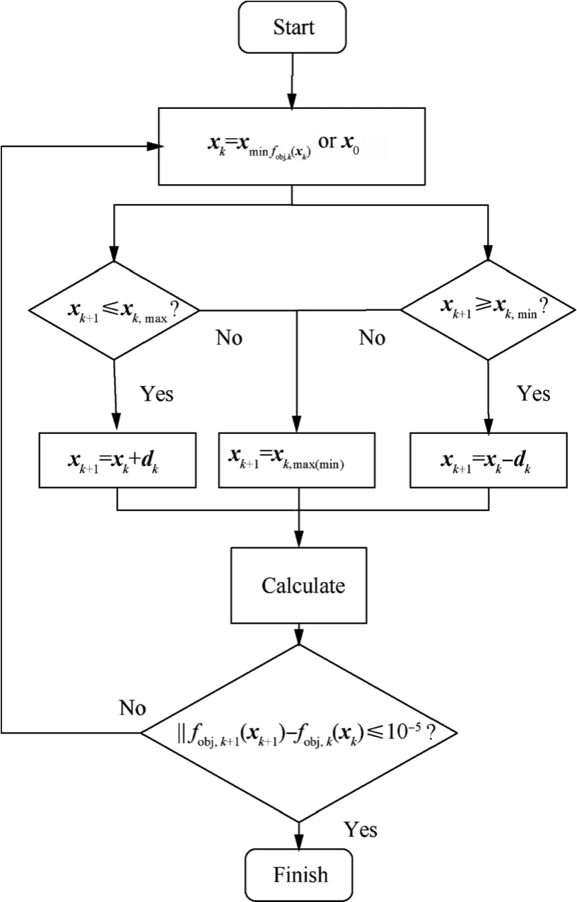
Fig.14 Calculation process of improved trust region algorithm.
Step 1.Calculatefobj,k(xk)at current point xk,andfobj,k(xk,1),fobj,k(xk,2)at the two points xk±dk.Comparingfobj,k(xk)withfobj,k(xk,1)andfobj,k(xk,2),iffobj,k(xk)is better,then jump to Step 3;otherwise,jump to Step 2.
Step 2.Take the one in xk,1and xk,2which has the smallerfobj,kas the current point,dk=dk-1-Δdk,and jump to Step 1.
Step 3.Let xkbe the current point again,dk=dk-1+Δdk,and jump to Step 1.
When the step size is greater than(less than)the maximum step size (minimum step size),the current step size will bemaintained,and the calculation ends when‖fobj,k+1(xk+1)-fobj,k(xk)‖≤10-5.
5.Simulation results
5.1.Simulation on accuracy
The simulation conditions areH=2 km,Ma=0.15 andH=3 km,Ma=0.2,representing the design condition and off-design condition respectively.The angle of attack increases rapidly at first,maintains the biggest state for seconds,and then decreases to 0.The aircraft entering the high angle of attack state at a faster speed can reduce the possibility of the aircraft stalling or entering a spin.The descending speed of angle of attack is pivotal for the reason that a negative angle of attack state may arise when it is too fast,and speed loss or even stall will be caused if it is too slow.The change of angle of attack adopted in this paper is given as
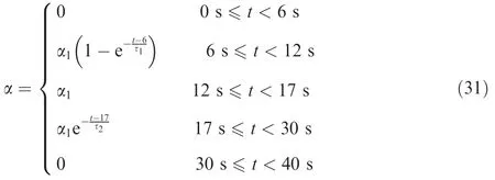
where α1is the final angle of attack value,τ1and τ2are the time constant,and α1=60°,τ1=0.8 s,τ2=2 s.Fig.15 shows the trend curve of the angle of attack.At the momentt=6 s,the angle of attack needs to be quickly increased to 60°,which can reduce the possibility of the aircraft stalling or entering a spin.Keep the state for 5 s,and it begins to decrease att=17 s.
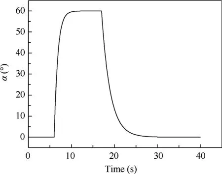
Fig.15 Changing trend of angle of attack.
Fig.16 shows the simulation results of the integrated optimization based on the improved trust region algorithm and conventional control including independent engine control and inlet open-loop control which is designed atH=2 km,Ma=0.15.The red curve with triangle is the integrated control result,the black curve with circular is the result of independent engine control,and the blue curve with square is the result of inlet open-loop control.All the parameters except surge margin have been normalized.
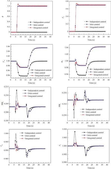
Fig.16 Simulation results at H=2 km, Ma=0.15.
Under design condition,the changes of the auxiliary intake valve of the open-loop control and the integrated control are almost the same.Although there is additional resistanceFfafter the auxiliary intake valve is opened,the absolute value of the additional resistance is far less than the additional thrust produced by the increase of intake flow,making the installation thrust increase.Without opening the auxiliary intake valve,the installed thrust is reduced by 6.16% and the flow rate is reduced by 4.21% when the angle of attack is 60° as shown in Table 1.The optimal opening of the auxiliary intake valve of online integrated optimization is 28°,and the flow rate is reduced by 1.25%.Compared with the traditional independent control,the flow rate is reduced by 2.96%at this time.As the air flow rate provided by the inlet increases,the degree of airflow expansion after the oblique shock wave decreases,σ begins to increase,and the performance of the propulsion system is improved significantly.The installation thrust drops to 2.55%,which is an increase of 3.61% compared to the independent control in the same state.Compared with the inlet open-loop control method,the installation thrust of integrated control keeps the same trend,and the largest thrust drop is almost equal under design condition.Besides,at the initial moment of the increase of angle of attack,the high-and low-pressure surge margin of integrated control and inlet open-loop control droop decrease,and the overshoot of the high turbine inlet temperature and the rotor speed decrease significantly.It can be seen that the online optimization of the auxiliary intake valve not only improves the installation thrust and intake flow,but also ensures the safety of the propulsion system in the transition process,making it aloof from the surge margin,temperature,and rotor speed boundary.

Table 1 Comparison of propulsion performance at design point.
Fig.17 shows the simulation results of three control methods under the off-design conditionH=3 km,Ma=0.2.Under this condition,the optimal opening of the auxiliary intake valve is distinct at different angles of attack.The auxiliary intake valve angle calculated by integrated control method changes with angle of attack.And the additional resistanceFfis smaller than inlet open-loop control duringt=6–12 s.As a result,the integrated control result is apparently superior to both independent control and inlet open-loop control in installation thrust.As shown in Table 2,the thrust of integrated control increases by 4.64%compared with independent engine control and by 2.88% compared with open-loop inlet control.The high-and low-pressure surge margin of integrated control droop decrease,and the overshoot of the rotor speed of integrated control and inlet control decreases significantly.
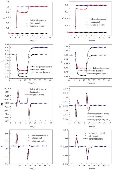
Fig.17 Simulation results at H=3 km, Ma=0.2.
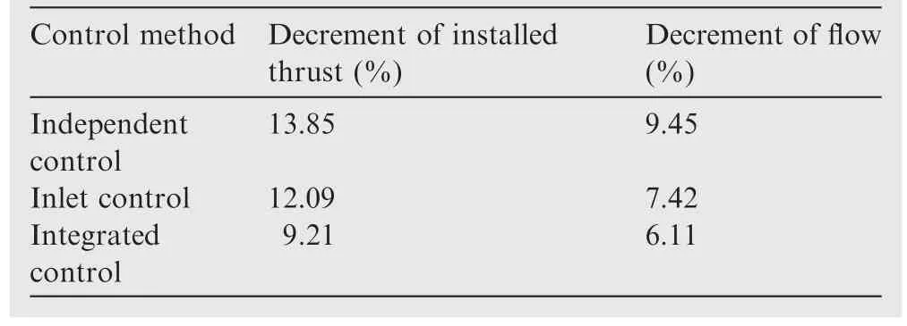
Table 2 Comparison of propulsion performance at off-design point.
Digital simulations are carried out in the same test environment: Win10,Visual Studio 2015,Intel i9-9900 k,16 GB RAM.Fig.18 shows the optimization simulation time,inwhich the average single-step time is 0.16 ms,and the maximum single-step time is less than 0.4 ms,which is less than the restricted time 25 ms.
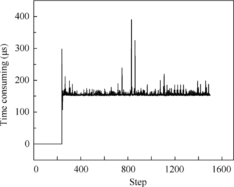
Fig.18 Time consumption of single-step calculation.
5.2.Simulation on hardware-in-the-loop platform
In the process of aeroengine control system development,several tests are essential before flight test,including digital simulation,hardware-in-the-loop simulation,semi-physical simulation and bench test.The hardware-in-the-loop simulation32takes the Engine Electronic Controller(EEC)as the simulation environment of control algorithm,which can verify the accuracy and real-time performance of algorithm,avoid the semi-physical simulation risk,and cut the development cost.
To verify the real-time performance of integrated control,simulation is carried out on HIL platform.The results are shown in Fig.19.Because of the influence of sensor simulator,there is jitter in the data.Taking the average value for analysis,installation thrust loss of integrated control reduces by 3.22%compared with independent engine control.All the restrictions are met in the process of maneuver.From the simulation results,it can be seen that the integrated optimization method covers the real-time requirements of EEC,and the results on HIL are generally consistent with the digital simulation results.
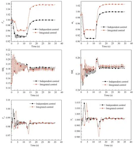
Fig.19 Simulation results on HIL at H=2 km, Ma=0.15.
Simulation results on HIL platform atH=3 km,Ma=0.2 are displayed in Fig.20.The installation thrust loss of independent engine control and integrated optimization control at α=60°are 13.88%and 9.27%(on average)respectively,which means that the loss reduces by 4.61%.Compared with independent engine control,the fan surge margin of integrated control moves down,but on the contrary,the compressor surge margin shifts up,which are all within the safety margin.The maxTt4andNfduring the maneuver process decline.In general,the integrated optimization control reduces the installation thrust loss and maintains safety margin of engine.
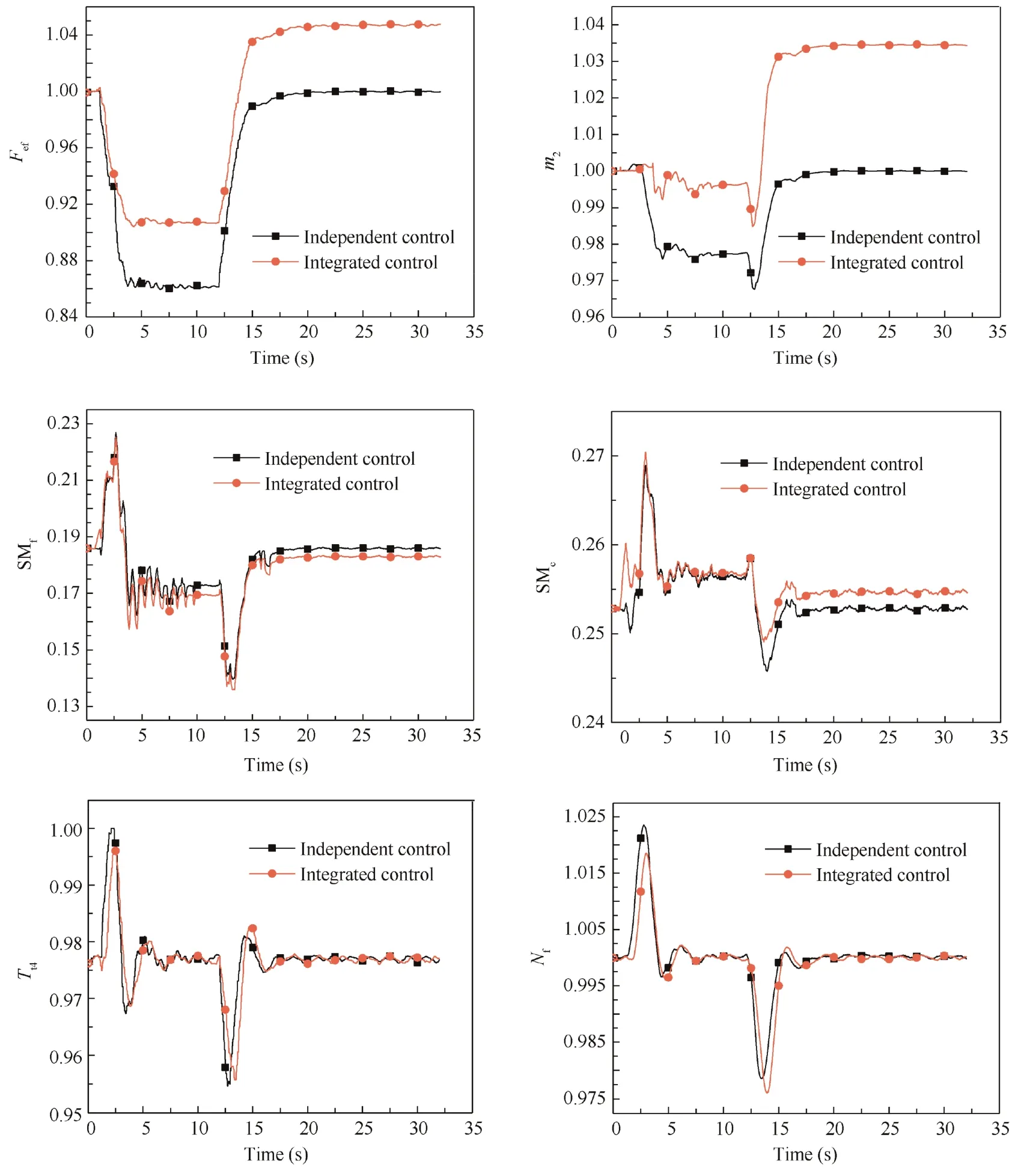
Fig.20 Simulation result on HIL at H=3 km, Ma=0.2.
6.Conclusions
In this paper,the integrated online real-time optimization study of inlet and engine during the maneuvering flight at a high angle of attack is carried out.Research on the supersonic inlet shows that the auxiliary intake valve is beneficial to improving the performance during maneuvering at high angle of attack.For example,when the opening degree is 40°,the total pressure recovery coefficient of inlet increases by 4.38%,and the air flow increases by 3.572%.Furthermore,Newton-Raphson method is adopted to solve the flow balance equation between inlet and engine,and the integrated onboard model can track the state of the propulsion system and calculate the unmeasured performance of the propulsion system accurately,which lays a foundation for online optimization.Aimed at the problem of insufficient real-time performance of traditional trust region algorithms,an improved trust region algorithm is proposed.This method focuses on the global optimal solution of the dynamic process and improves simulation speed by saving the calculation time of second derivative and Hessian matrix.The optimal auxiliary intake valve opening is different under various angles of attack and flying conditions,which makes the inlet open-loop control less effective than the integrated control under off-design conditions.The real-time optimization result of propulsion system indicates that the online optimization for auxiliary intake valve with installed thrust as the objective improves the matching performance of supersonic inlet and engine,which brings propulsion system additional performance benefits.Besides,simulation on HIL platform is carried out to verify the real-time performance of integrated optimization control,and the results are consistent with the digital simulation results.
Declaration of Competing Interest
The authors declare that they have no known competing financial interests or personal relationships that could have appeared to influence the work reported in this paper.
Acknowledgements
This study was supported in part by the National Natural Science Foundation of China (Nos.51906102 and 52176009),in part by the National Science and Technology Major Project,China(Nos.J2019-II-0009-0053,J2019-I-0020-0019 and 2019-III-0014-0058),in part by the Innovation Centre for Advanced Aviation Power,China (Nos.HKCX2020-02-022 and HKCX2020-02-027),in part by the Research on the Basic Problem of Intelligent Aero-engine,China (No.2017-JCJQZD-047-21),in part by the Fundamental Research Funds for the Central Universities,China (No.NZ2020002).
 CHINESE JOURNAL OF AERONAUTICS2022年12期
- CHINESE JOURNAL OF AERONAUTICS的其它文章
- Control and utilization of range-dependent beampattern with waveform diverse array radars
- Airside pressure drop characteristics of three analogous serpentine tube heat exchangers considering heat transfer for aero-engine cooling
- Numerical analysis of deflection control of a gas plasma jet based on magnetohydrodynamic staggered electrode configuration
- Neural network-based model predictive control with fuzzy-SQP optimization for direct thrust control of turbofan engine
- Method for utilizing PIV to investigate high curvature and acceleration boundary layer flows around the compressor blade leading edge
- Experimental investigation of expansion effect on shock wave boundary layer interaction near a compression ramp
