Conceptual design and flight test of two wingtipdocked multi-body aircraft
Yang MENG,Chao AN,Changchuan XIE,Chao YANG
School of Aeronautic Science and Engineering,Beihang University,Beijing 100083,China
KEYWORDS Flight test;Multi-body aircraft;New conceptual aircraft;PID control;Wingtip-docking mechanism
Abstract To overcome the drawbacks such as large wing deformations,poor performance encountering gusts,limits in taking off and landing,inconvenience of transportation of High-Altitude Long-Endurance (HALE) Unmanned Aerial Vehicles (UAVs),a new conceptual aircraft called wingtip-docked Multi-Body Aircraft (MBA) has attracted lots of attentions.Aiming to investigate the feasibility of this concept,two UAV models were designed,manufactured and connected by a wingtip-docking mechanism,which only allows the relative roll motion between the two aircraft.The trim solution of the two connected aircraft is firstly obtained by solving the developed nonlinear flight dynamic equations,followed by the stability analysis based on the linearized model.The results show that the connected aircraft is inherently unstable and cannot fly without a reasonable flight control system.A set of Proportional-Integral-Derivative (PID) control laws was then developed and implemented in the two experimental aircraft.The success of the flight tests show that the flight control can effectively eliminate the unstable motion and the wingtip-docked MBA is controllable and feasible.
1.Introduction
High-Altitude Long-Endurance (HALE) Unmanned Aerial Vehicles (UAVs) have wide applications in military and civil field for long-term surveillance,environmental monitoring and communication tasks.Benefit from light weight and high aspect ratio,they can stay in the stratosphere for up to 336 hours (see Zephyr1).However,the large wing span can lead to large deformation during flight,which further causes significant changes in structural dynamics and aeroelastic behaviors.Additionally,the flight dynamic modes and the low-frequency aeroelastic modes due to the high flexibility may couple with each other,resulting in a dynamic instability.After the famous mishap of NASA Helios,2numerous studies have been focused on multidisciplinary modeling and nonlinear aeroelastic analysis,3–9aiming to develop a complete framework for predicting performances and flight-control-system design of HALE UAVs.However,these efforts are difficult to eliminate the inherent drawbacks such as poor performance encountering gusts,limits in taking off and landing and inconvenience of transportation.
An alternative to single fixed-wing HALE UAVs is joined aircraft or called Multi-Body Aircraft (MBA).In the 1950s,the U.S.Air Force firstly investigated the concept of wingtip-docked aircraft with projects TipTow and Tom-Tom.10Two F-84D jet fighters were combined to the wingtips of one B-29A to demonstrate the full-scale feasibility of this concept and to prove the drag-reducing benefits of wingtip towing.Magill et al.11,12shows that the combined aircraft can improve the range performance by 20%to 40%.Although the project was finally abandoned due to the high risk and the practicality of aerial refueling technology,the inspiration it brought to aircraft design continues up to today.As for the application in HALE field,the concept is extended to linking a set of independent multifunctional aircraft during flight to form a larger flight platform so as to achieve a high aspect ratio or high lift-to-drag ratio with no consideration of structural geometric nonlinearities.The modular aircraft can take off individually or be brought to the stratosphere by a large transport airplane and hence avoid large bending moments caused by gust disturbance in the troposphere.It should be emphasized that the wingtip connections are articulated constraints to prohibit a transfer of bending moment,which is beneficial to the lightweight design.Moreover,multi-body aircraft can carry different types of payloads to achieve diverse missions.The modularity of MBA permits the separation and replacement of a single individual aircraft to guarantee the performance without greatly affecting the flight mission.
Despite of the aforementioned advantages,there are great challenges in aerodynamics,flight dynamics and flight control of MBA.The main problems needed to be resolved are as follows:
(1) flight path control of single aircraft and precise positioning of wing tips;
(2) aerodynamic interaction in close-proximity flight;
(3) design of wingtip-docking mechanism;
(4) flight dynamics and stability features of wingtip-docked MBA;
(5) flight control of wingtip-docked MBA.
The first three problems are crucial to the linkage of several aircraft during flight,while the last two would be the most important matter to demonstrate the feasibility and controllability of connected flight.This work will focus on the connected flight.Kothe et al.13,14from Germany investigated the concept of a Multi-Body High Altitude Pseudo Satellite aircraft for surveillance and communication tasks.Based on the Kane method and lift-line theory,they studied the dynamic characteristics of two configurations of MBA.The first one permits a relative pitch motion between individual aircraft and the second configuration permits both pitch and roll motions.Results show that unstable motions occur in both two configurations.A flight path control law was then developed based on the flight dynamic model.Recently,the research group further investigated the aerodynamic interaction between two wings with close lateral proximity from both numerical and experimental perspectives.15The results show that the relative position between wing tips is a key factor on aerodynamic forces and moments.
More recently,Montalvo and Costello16,17have accomplished the flight dynamics research on meta aircraft,which is similar to the concept of MBA.Except for wingtip-towingtip configuration,tip-to-tail configuration was also considered in their research.Montalvo et al.18,19further investigated the controllability of these aircraft.Carithers and Montalvo20finally connected two fixed-wing aircraft at both the wing tips and tail tips by three strong neodymium magnets and carried out the flight test.After upgraded autopilot hardware and software,Cobar and Montalvo21further presented flight test of takeoff and landing of a meta aircraft and demonstrated successful performance of the feedback control.It should be noted that the connected aircraft was not inherently unstable in their tests due to the magnetic forces between the wingtips.Under the auspices of NASA-led Project Link!,Cooper and Rothhaar22have developed the dynamic models for both individual and connected aircraft including linking forces and close-proximity aerodynamic interactions,and simulated the linking and linked flight.An et al.23emphasized the inherent instability of two wingtip-docked aircraft that permit a roll motion between each other.Newton-Euler equation is applied for modeling of multi-body dynamic system with absolute coordinates and the lifting line theory is used for calculation of aerodynamic derivatives.The results show that the stability augmentation control law must be deliberately designed to achieve stable flight for MBA.
Following the theoretical work in Ref.[23],this paper aims to investigate the feasibility and controllability of MBA from an experimental perspective.Two UAV models were designed,manufactured and connected by the wingtip-docking mechanism ‘‘printed” on a 3D printer.A Proportional-Integral-Deri vative (PID)control law is designed and applied in the whole flight to exclude the unstable motions.The following sections will describe the aircraft,flight dynamics and stability analysis,flight control and experimental results in detail.
2.Model design
2.1.Airframe layout
In this paper,several independent aircrafts are connected at wing tips to form a large aspect ratio platform.The wingtipto-wingtip configuration permits a roll motion between independent aircraft with a hinge joint.All other degrees of freedom including three translational motions,pitch motion and yaw motion between two connected aircraft are constrained.The used joint prohibits a transfer of bending moment which dominates the strength distribution and hence the reduction of structural weight.The schematic configuration of MBA is shown in Fig.1.

Fig.1 Illustration of MBA with five individual aircraft.
The overall aerodynamic design of the individual aircraft was inspired by X-HALE,24which was designed for nonlinear aeroelastic tests.A high-aspect-ratio design is adopted to achieve a high lift-to-drag ratio.Meanwhile,double fuselage configuration can effectively avoid the large deformation.A schematic of the aircraft is shown in Fig.2.Its main geometric features are presented in Fig.3,and some key parameters are listed in Table 1.The aircraft has a 3-meters wingspan consisting of three identical one-meter segments,a chord length of 0.27 m,two 0.896-m booms with vertical and horizontal tails attached,and two fuselages with landing gears,batteries,propellers and flight controller.The total mass of each single aircraft is about 4.95 kg with an anticipated flight speed during 10–30 m/s.
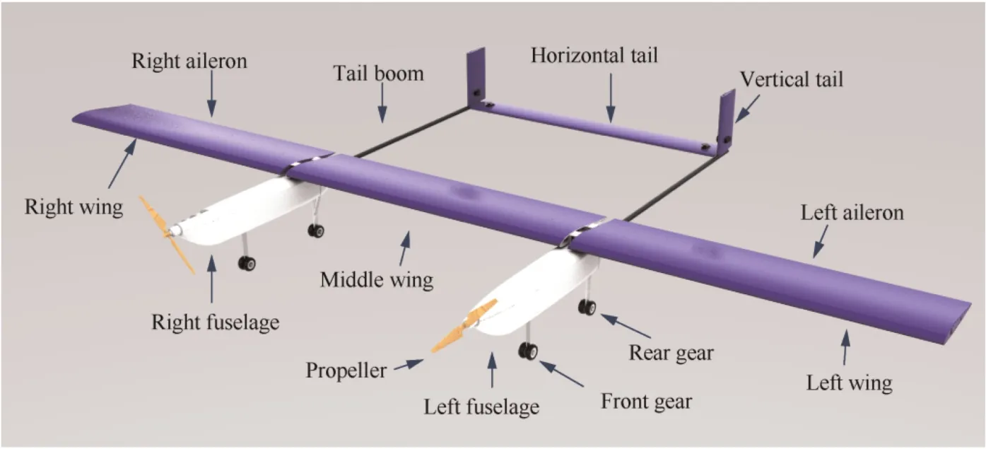
Fig.2 Schematic of the single aircraft.
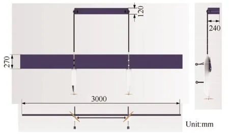
Fig.3 Three views of the single aircraft.
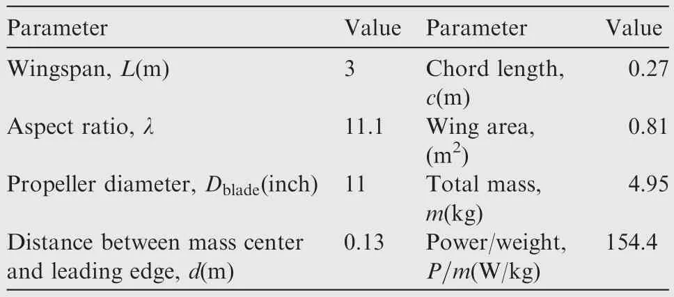
Table 1 Key parameters of the individual aircraft.
Each fuselage contains a 14.8 V/2200mAh lithium polymer battery to power the motor with a mechanical power of 382 W.The motor together with a 11× 7E APC propeller can supply a maximum thrust of 22.6 N leading to a maximum thrustweight ratio 1.0.Two landing gears are connected to a carbon bar across the fuselage.The front gear is driven by a servo to adjust the sliding direction.
Fig.4 describes the general layout of the onboard system.The flight controller is mounted to the left fuselage and a counterweight is arranged on the right fuselage to play a balance role.There are totally eight servos for controlling aileron,rudder,elevator and the front gear.All the servos are connected to the flight controller and to realize the differential control of the ailerons on the left and right sides and simultaneous control of elevator and rudders.In this work,each individual aircraft has its own flight control system and receiver.The receivers of two aircraft are in the same frequency band,so as to receive the command signal from the remote controller or the ground station at the same time and make consistent reactions.
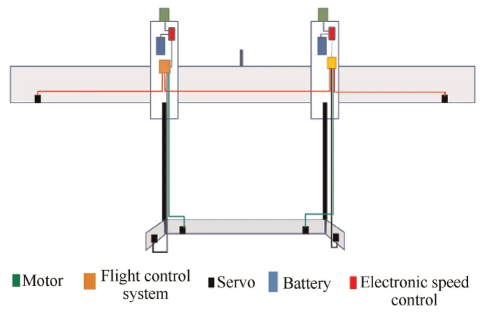
Fig.4 General layout of the onboard system.
2.2.Airfoil design and aerodynamic characteristics
The airfoil was selected referred to the Helios and X-HALE.The EMX07 airfoil is the final choice for the main wing after trading the lift-to-drag ratio,zero-lift pitching moment coefficient and stall angle.The profile of the EMX07 airfoil is depicted in Fig.5.NACA0012 airfoils are chosen for horizontal and vertical tails.With a chord of 0.27 and 0.12 m,respectively,the main wing and tail Reynolds number are around 350000 and 150000 at a 20 m/s reference cruise velocity.Fig.5 displays the distributed pressure profile of these two airfoils.Fig.6 plots the basic aerodynamic coefficients includingCL,CDandCmfor these two airfoils at the operating Reynolds number.The reference point for the pitch moment coefficient is located at 1/4 chord length.All of the data were computed by XFOIL.

Fig.5 EMX07 airfoil to be used in the main wing and NACA0012 airfoil to be used in the tails.
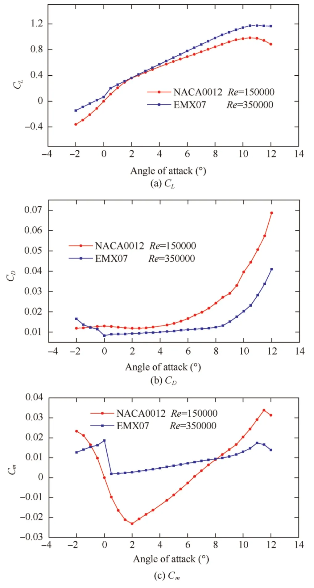
Fig.6 Aerodynamic characteristics of EMX07 and NACA0012(results from XFOIL).
The aerodynamic characteristics of both the individual and connected aircraft were then evaluated in Xflr 5 for preliminary aerodynamic analysis and conceptual design.The pressure distribution on the main wing and tails of the individual aircraft(without considering the fuselage)at sea level is shown in Fig.7.The airspeed and the Angle of Attack(AOA)were set as 20 m/s and 4°,respectively.The result also provides the location of aerodynamic center,which is 0.16 m away from the leading edge.Recalling that the mass center is 0.13 m away from the leading edge,the static margin of the single aircraft is about 11%MAC (Mean Aerodynamic Chord).
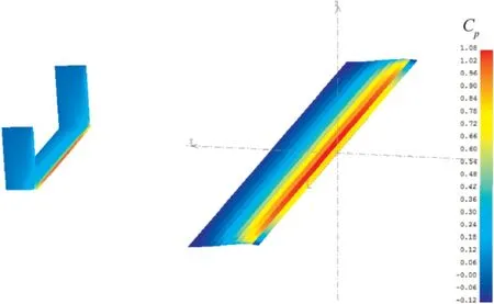
Fig.7 Pressure distributions of the single aircraft.
In particular,the lift-to-drag ratios of the individual and two connected aircraft varying with AOAs are plotted and compared in Fig.8.With the increase of aspect ratio,the maximum lift-to-drag ratio increases from 24.5 to 31.4.It is noteworthy that the lift-to-drag ratios may inaccurate due to the limitation of Xflr in simulating drag.
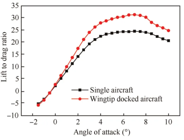
Fig.8 Lift-to-drag ratios to angles of attack.
2.3.Wingtip docking mechanism
The used wingtip docking mechanism is shown in Fig.9.It consists of two parts,one of which is mounted to the right wingtip of the left aircraft and the other one is mounted to the left wingtip of the right aircraft.There is only one shaft in the mechanical joint,prohibiting a transfer of bending moment,but allowing pitch and yaw moment as well as all forces in all directions.The mechanism is manufactured by a 3D printer and permits a maximum relative roll angle of 30°.

Fig.9 3D printed wingtip docking mechanism.
3.Flight dynamics and stability analysis
Different from the classical flight dynamic equations,the equations of motion of MBA are typical differential algebraic equations due to the extra constraints.The multibody dynamic modeling is based on Newton-Euler equations,and the aerodynamic forces are calculated by the lift line theory.Subsequently,the trim solution is obtained by solving the nonlinear flight dynamic model.Finally,one can investigate the stability characteristics of the multibody system by linearization of the nonlinear model about the trim state.
3.1.Flight dynamics
As shown in Fig.10,the state vector for deriving equations of motion of two wingtip-docked aircraft can be chosen as
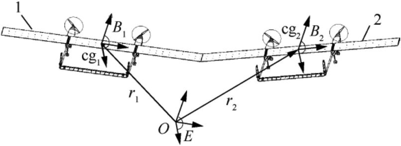
Fig.10 Illustration of two wingtip-docked MBA.
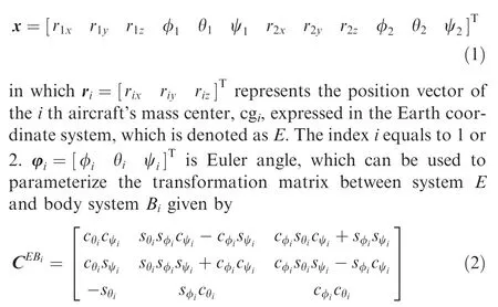
wheresθ≡sinθ andcθ≡cosθ.

The equations of motion then can be derived with Euler’s law:
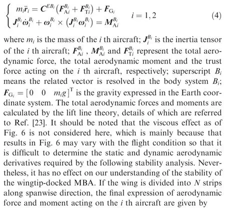
where CBiadenotes the transformation matrix from the aerodynamic coordinate systemato the body systemBi;rijdenotes the distance vector from mass center of theith aircraft to the collocation point of thejth strip;andDj,Yj,Ljare the induced drag,side force and lift of thejth strip respectively.
Considering the joint prohibiting a roll motion between these two aircraft and assuming that the joint is ideal without any friction,damping and spring forces,five constraint equations can be given by

where r10and r20represent the direction vector from the mass center cg1,cg2to the connection point,respectively.dBιis the direction vector along the shaft corresponding to the roll motion within theith aircraft.It is clear that the first equation in Eq.(6)restrict the relative translational motions and the second one prohibits the yaw and pitch motions.The constrain equations can also be rewritten in a simplified form as

Taking derivative of Eq.(7) with respect to timet,one can obtain

where the subscript denotes the partial derivative,e.g.Φx=∂Φ/∂x and Φxx=∂(∂Φ/∂x)/∂x.
Combing Eq.(8)with Eq.(4),the equations of motion with constraints of MBA can be given by
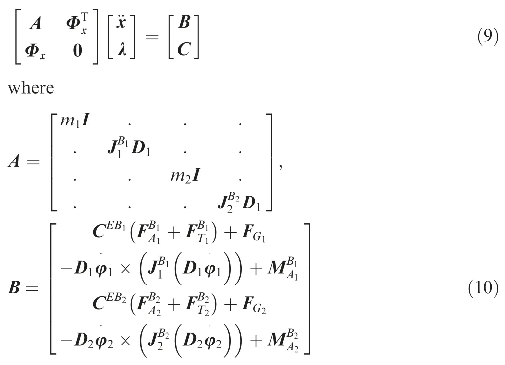

and λ is the Lagrange multiplier conjugated to constrains;I is the 3×3 identity matrix.
Under specified flight conditions,the solution of Eq.(9)provide the trim results of the multibody aircraft.A statespace model can be obtained by linearizing the nonlinear equations of motion about the trim state.For simplicity,the nonlinear flight dynamic equations are written as

3.2.Stability analysis
For two wingtip-docked multibody aircraft,the flight dynamic equations include 12 rigid-body motion equations and 5 constraint equations and hence there remains 7 degrees of freedom within the system.In current work,each individual aircraft consists of 5 control surfaces containing two ailerons,one elevator and two rudders.Two ailerons deflect with the same angle but in opposite directions while two rudders always maintain the same deflection.Besides,it is assumed that the elevator deflections of two aircraft keep the same.As a result,seven trim variables are specified as

where αiis the angle of attack;δeand δaiare the elevator deflection and aileron deflection respectively;φiis the roll angle.
Based on the nonlinear dynamic equations,the experimental multibody aircraft is trimmed under an airspeed of 20 m/s at sea level.The trim results are listed in Table 2.The trim configuration is shown in Fig.11.A symmetrical configuration was achieved under the specified flight condition.AOA of two aircraft reach to the same value due to the restriction of pitch motion.Here,thex-axis is defined to be opposite to the direction of incoming flow,they-axis is towards to the right wing tip,and thez-axis is defined according to the right-hand rule.With this definition,the positive value of φ1and negative value of φ2result in a positive-dihedral configuration of the two aircraft.
The stability analysis can then be carried out based on the trim state.Table 3 presents the main results of the eigenvalue analysis.For a complex mode,the eigenvalues λ and characteristic time τ are defined as follows:
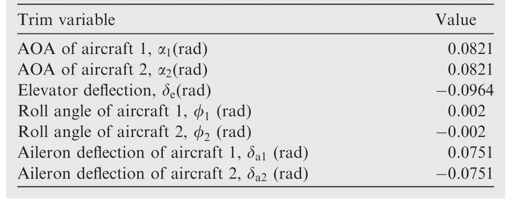
Table 2 Trim results.

Table 3 Results of eigenvalue analysis.

where ωnis the characteristic frequency and ζ is the damping ratio.
While for a real mode,the characteristic time is half-life time τ1/2when stable or double-amplitude timet2when unstable,given by:

where the eigenvalue is denoted by λ0to distinguish from the complex mode.
Except for the classical flight dynamics modes,there are two compound modes exhibiting as positive-or negativedihedral configuration,respectively.The first relative roll mode is corresponding to the positive one,as shown in Fig.11.Its eigenvalue is negative indicating a stable motion.The second relative roll mode is shown in Fig.12.The positive eigenvalue means this mode is unstable and has a very short double-amplitude time of 0.725 s.Characteristic time of phugoid mode is very long so that its effect can be neglected despite of the instability.The results show that the wingtipdocked MBA is inherently unstable and cannot fly without a reasonable flight control system.

Fig.11 Illustration of trim state.

Fig.12 Relative roll mode 2.
4.Flight control design
Due to the unstable compound mode,a particular stability augmentation control system is required to ensure the stable flight of two MBA system.In Kothe et al.’s research,14the experimental MBA consists of three single aircraft and only the middle one has a Core Processing Module(CPM)on which the flight control laws are processed.The sensor values of two outer aircraft have to be transmitted to the CPM in the middle aircraft.Besides,the wing shape holding which is evaluated by differences of pitch and roll angles of the outer aircraft referring to the middle aircraft is expected to be controlled.However,this manner makes the control law complex for MBA and deviates from the basic idea that each aircraft has a flight control system to achieve taking off,landing and flight mission independently.
An alternative manner is to achieve a consistent state by controlling each aircraft separately.The control system aims to maintain each aircraft level in both roll and pitch,which naturally realize the wing shape holding.Although the flight dynamics of MBA show great differences from the classical single aircraft,the basic principle for traditional control design was applied to the experimental MBA.The whole flight control law consists of the outer-and inner-loop control.The outer-loop is designed for attitude control and path control,while the inner-loop is designed for stability control.PID controllers were designed and achieved via the following control surfaces:elevator for pitch angle,a pair of ailerons in differential motion for roll angle.The rudder is not used in the feedback control but serves as an auxiliary manner for turning the aircraft.In practice,the feedback signals are obtained from a Kalman filter processing multiple sensors.The inner-loop controllers are given as:where δeiand δaiare the elevator and aileron deflections,respectively;the subscript cmd refers to the command signal;Kp,KiandKdare the proportional,integral,and derivative gains,respectively;the subscript θ,zand φ denotes the gains are related to the pitch angle deviation,altitude deviation and roll angle deviation,respectively.In the following flight tests,the above gains of each aircraft are set to the same.The control law designed in this way can be easily extended to the connected aircraft withNindividual aircraft.
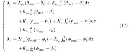
Fig.13 shows the responses of the roll angle simulated by MATLAB Simulink Module.Based on the trim state,a small disturbance of 0.008 rad was applied on the roll angle.The open-loop responses (with no control) diverge rapidly and once again demonstrates the unstable inherence of the two wingtip-docked multi-body aircraft.In contrast,the closedloop responses (with control) converge within a short time,and hence the stable flight is completely fulfilled.
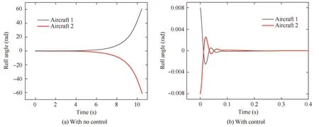
Fig.13 Roll angle response with no control and with control.
In this work,each aircraft of the experimental multi-body aircraft is equipped with an independent flight control module,whose basic architecture is shown in Fig.14.The flight control laws are processed on an ARM (Advanced RISC Machines)module.The input module gets signals from MEMS gyroscope(angular velocity measurement,±300°()/s),3-axis accelerometer (±2g),barometer (15–115 kPa),Pitot (0–4 Ka) and GPS receiver (4 Hz).The remote receiver sends the pilot inputs to the ARM.After computing the actuator signals by the flight control laws,the ARM sends the commands to four servo motors for aileron,elevator,rudder and front gears as well as to the engine controller by PMW signals.The corresponding four control channels are denoted by S1,S2,S3 and S4,respectively.The power for the whole flight control system of each aircraft is supplied by two 14.8 V lithium batteries.
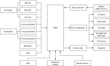
Fig.14 Basic architecture of flight control module.
5.Flight test and result analysis
To investigate the controllability of the wingtip-docked MBA,two 3-meter wingspan aircraft are connected by a 3D printed wingtip docking mechanism and tested without and with inner-loop control system,respectively.The detailed parameters of the aircraft are listed in Table 1.
As aforementioned,each individual aircraft is equipped with an independent flight control module,which integrates a receiver,GPS,acceleration sensor,gyroscope,airspeed tube and other sensors.The pilot can thus control both aircraft simultaneously.There are two control modes involved in this test: Remote Control (RC) mode and Remote Piloted Vehicle(RPV) mode.In RC mode,the control surface including the aileron,elevator and rudder and the engine react directly to the commands of the remote controller in absence of the inner-loop PID control.When the pilot switches the RPV mode on,feedbacks from sensing signals are introduced to the PID control law to actuate the ailerons,elevators and propellers to achieve the pitch/roll holding.
Fig.15 shows the unstable motion during taking-off phase.The control mode was set in RC mode.It was found that the inside landing gears get off the ground firstly leading to a negative-dihedral configuration,which is consistent with the unstable compound flapping mode as shown in Fig.12.From an aerodynamic perspective,the linked wings (inner wings)experience more lift than the outward wings leading to a roll moment acting on both aircraft.The finding confirms that the wingtip-docked MBA is inherently unstable.

Fig.15 Unstable motion when taking off in RC mode.
In following flight tests,the RPV mode is switched on to achieve a stable flight.As shown in Fig.16,the connected aircraft successfully flew with the designed flight control system.The whole flight test lasted 241 s.Fig.17(a)plots the time histories of the flight path.The‘‘star”and the‘‘cube”correspond to the beginning and the end of the flight,respectively.The flight path is generally counterclockwise,which means‘‘Aircraft 1” (as shown in Fig.16) is on the inside.Therefore,both flight altitude and airspeed of ‘‘Aircraft 2” are slightly higher than those of‘‘Aircraft 1”.Fig.17(b)shows the altitude of the flight,the maximum of which is about 35 m.Fig.17(c)shows the airspeed detected by the pitot and the ground speed computed from the GPS data.The wind speed can be then evaluated by the difference between the airspeed and the ground speed.The maximum of airspeed is about 25 m/s,and the average is about 18 m/s.

Fig.16 Connected aircraft in flight.
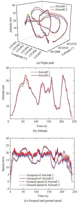
Fig.17 Flight path and speed recorded in flight.
Fig.18 (a) shows the experimental records of the pitch angle in flight.In this flight test,commands on the elevator of one aircraft keep the same as the other one.There is little difference between the pitch angles of the two aircraft due to the restriction of the wingtip joint.A sharp increase can be found in about 160 s after taking off,which is mainly due to the emergency pull-up operation as shown in Fig.18(c).It is worthy to point out that the deflection angle of the control surface plotted here is not the measured value since no angle feedback with the servo,but the reference value computed from the flight control command.The results show that the connected aircraft has good maneuverability in pitch motion.
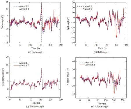
Fig.18 Experimental records of connected aircraft.
Fig.18(b)plots the time history of the recorded roll angle.The difference between the roll angle of the two aircraft is calculated by

and is shown in Fig.19.The unstable compound flapping motion was eliminated with the stability augmentation control.The maximum difference occurred in about 200 s after taking off.The relative roll angle was close to 30°,which is almost the design limit of the wingtip docking mechanism.The large difference can be attributed to the sharp lateral motion.The corresponding flight snapshot is shown in Fig.20.For the connected aircraft,any lateral motion will introduce complex flapping modes due to the discontinuity in the joint.It can be seen that the connected aircraft is turning left,and the roll angle of the outer aircraft is larger than the inner one due to a higher lift caused by higher airspeed.Accordingly,the autopilot immediately deflects the aileron to realize the wing shape holding within about 5 s,which further proves the effectiveness of the designed stability enhancement control system,and once again reflects that the aircraft has good maneuverability.
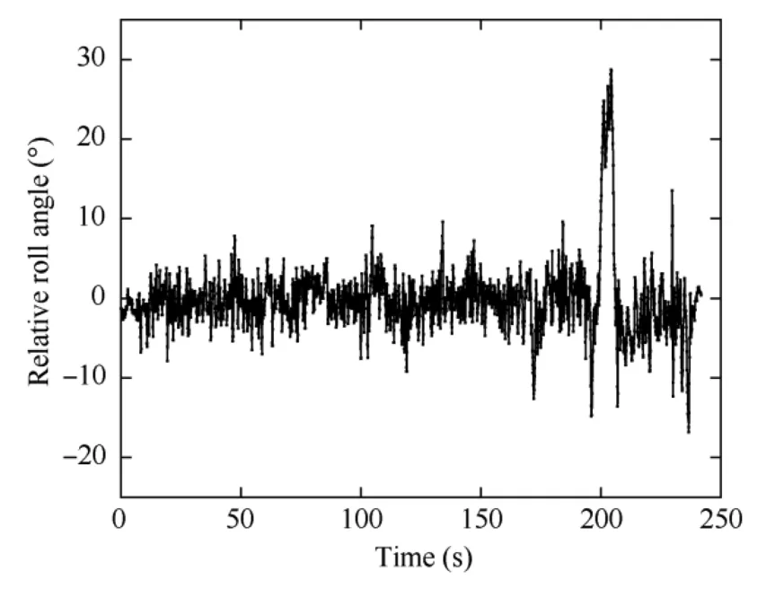
Fig.19 Relative roll angle in flight.
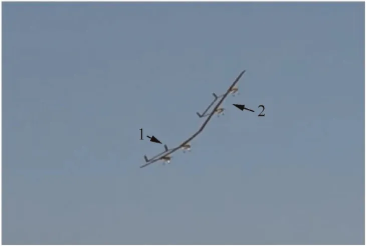
Fig.20 Connected aircraft at t=200 s.
6.Conclusions
1) A new conceptual wingtip-docked MBA was studied from both theoretical and experimental perspectives.Stability characteristics are investigated based on the linearized equations about trim state and the results show that the connected flight is inherently unstable due to divergent compound flapping mode.To ensure a stable flight,a stability augmentation control was designed and verified by numerical studies.
2) Two aerial models with large aspect-ratio wings and double fuselage were designed and manufactured.A 3D printed mechanism was used to connect two aircraft.The experimental phenomenon without stability augmentation control is consistent with the unstable motions found by numerical analysis.The successful flight with the developed flight control proves that the control laws are effective,and the wingtip-docked MBA has good controllability and maneuverability.
3) Future work will focus on the aerodynamic interaction in close-proximity flight and the linkage of several aircraft during flight.Moreover,more accurate aerodynamic modeling method will be used for trim analysis and stability analysis with the flight control.
Declaration of Competing Interest
The authors declare that they have no known competing financial interests or personal relationships that could have appeared to influence the work reported in this paper.
 CHINESE JOURNAL OF AERONAUTICS2022年12期
- CHINESE JOURNAL OF AERONAUTICS的其它文章
- Control and utilization of range-dependent beampattern with waveform diverse array radars
- Airside pressure drop characteristics of three analogous serpentine tube heat exchangers considering heat transfer for aero-engine cooling
- Numerical analysis of deflection control of a gas plasma jet based on magnetohydrodynamic staggered electrode configuration
- Neural network-based model predictive control with fuzzy-SQP optimization for direct thrust control of turbofan engine
- Method for utilizing PIV to investigate high curvature and acceleration boundary layer flows around the compressor blade leading edge
- Experimental investigation of expansion effect on shock wave boundary layer interaction near a compression ramp
