Lift enhancement based on virtual aerodynamic shape using a dual synthetic jet actuator
Shiqing LI,Zhenbing LUO,Xiong DENG,Zhiyong LIU,Tianxiang GAO,Zhijie ZHAO
College of Aerospace Science and Engineering,National University of Defense Technology,Changsha 410073,China
KEYWORDS Circulation control;Coanda effect;Dual synthetic jet actuator;Lift enhancement;Virtual aerodynamic shape
Abstract The Dual Synthetic Jet Actuator (DSJA) is used to develop a new type of lift enhancement device based on circulation control,and to control the flow over the two-dimensional (2D)NACA0015 airfoil.The lift enhancement device is composed of a DSJA and a rounded trailing edge(Coanda surface).The two outlets of the DSJA eject two jets(Jet 1 and Jet 2).Jet 1 ejects from the upper trailing edge,which increases the circulation of airfoil with the help of the Coanda surface.Jet 2 ejects from the lower trailing edge,which acts as a virtual flap.The Reynolds number based on the airfoil chord length and free flow velocity is 250000.The results indicate that the circulation control method based on Dual Synthetic Jet (DSJ) has good performance in lift enhancement,whose control effect is closely related to momentum coefficient and reduced frequency.With the increase of the reduced frequency,the control effect of the lift enhancement is slightly reduced.As the momentum coefficient increases,the control effect becomes better.When the angle of attack is greater than 4°,the increments of lift coefficients under the control of DSJ are larger than those under the control of the steady blowing at a same momentum coefficient.The maximum lift augmentation efficiency can reach 47 when the momentum coefficient is 0.02,which is higher than the value in the case with steady blowing jet circulation control.
1.Introduction
Circulation Control (CC) is one of the common technologies for lift enhancement.Its main principle is to delay the separation of the boundary layer with the help of the Coanda effect and the tangential jet at the trailing edge of the airfoil,so as to change the stagnation point position of the trailing edge of airfoil and then greatly improve the lift of an airfoil.1Compared with the traditional mechanical devices for lift enhancement,which contribute to noise and the weight of the aircraft,the circulation control technologies have the advantages of providing simplification of actuation.The application of CC also produces reduction in the weight and number of moving devices such as flaps and control surfaces.Therefore,it can reduce the specific weight of the devices for lift enhancement and reduce the cost of manufacturing and maintenance.1The use of CC instead of complex control surfaces for attitude control will also greatly reduce the Radar Cross-Section (RCS)and improve the stealth performance of fighter aircraft.In addition,the circulation control technologies can improve the lift coefficients of the aircraft,obtain more available lift increments,and then reduce the take-off speed and grounding speed of an aircraft,which shortens the sliding distances and improves take-off and landing performance of an aircraft.2.
According to the generation method of the trailing-edge tangential jet,the circulation control methods can be divided into different types.The most common method is steady blowing at upper trailing edge.Englar et al.3investigated the CC effect of steady blowing on the CC020-010EJ airfoil.They found that after the CC is applied,positive lift coefficients can even be generated at negative angles of attack.As the momentum coefficient increases,the stalling angle of airfoil advances.When the angle of attack is large,the flow separation occurs at the leading edge of the airfoil.A large amount of blowing is required to obtain considerable increments of lift coefficients at large angles of attack.On the basis of steady blowing method,the pulsed blowing method is derived.Jones et al.4–5researched the control effect of the pulsed blowing and the steady blowing.They found that pulsed blowing can reduce the mass flow requirements for a desired lift coefficient by more than 50%.Conversely,for the same available mass flow rate or the same momentum coefficient,pulsed blowing allows considerably higher lift increments to be generated.Liu et al.6also found that for the same available mass flow rate or the same momentum coefficient,the pulsed blowing excited by the square wave can produce a larger lift increment than steady blowing,and pulsed blowing control has better control effect at higher frequencies.
Although the control effect of blowing jet is so significant,its most obvious drawback is the requirement of air source supply.1With the development of active flow control methods,the method of generating trailing-edge tangential jet is no longer limited to steady blowing or pulsed blowing.More and more zero-mass jet technologies are applied for CC.Feng et al.7investigated the effect of plasma circulation control on a NACA0012 airfoil and an unmanned aerial vehicle without and with flaps deflection.They found that with the plasma circulation control,a steady recirculation region will be formed on the pressure surface near the trailing edge and acts as a virtual flap,and thus the circulation over the airfoil is increased.Moreover,the plasma control increased the lift coefficients over the entire angles of attack.Zhang et al.8found that the efficiency-cost ratio (ΔCL/Cμ,where ΔCLis the increment of lift coefficient) of plasma circulation control is relatively high,which makes it an attractive lift-enhancement method for applications.Zhanget al.1used the Synthetic Jet (SJ) circulation control to enhance the lift of NCCR1510-7067N airfoil.They found that the synthetic jet can effectively delay the separation point on the trailing edge of the airfoil and increase the circulation of airfoil.And the maximum lift augmentation efficiency reaches ΔCL/Cμ=114,which is much higher than 12.1 in the case with steady blowing.Pititat and Rajnish9used Large-Eddy Simulation (LES) to research the circulation control effect of the synthetic jet on the NACA0015 airfoil.They found that the synthetic jet has achieved a good effect in lift enhancement especially at a low angle of attack.WhenCμis low,the lift coefficient increases almost linearly.
Compared to those cases with steady blowing or pulsed blowing,the CC method based on the zero-mass jet technologies has the characteristics of only outputting momentum to the outside.The quality that outputs from the zero-mass synthetic jet actuator is 0.And the zero-mass actuator does not require an air source and piping systems.1It must be pointed out that although the zero-mass jet CC technologies have made some progresses currently,there is a general problem,that is,the controllable flow velocity is relatively low.1,8Such a problem limits the applications of zero-mass jet circulation control.It is of great significance to further explore novel CC methods with strong control effect and great potential in applications.
Based on the dual synthetic jet actuator,10–11this paper proposes a new type of device and method for increasing lift.This paper uses the RANS method to study the control effect on a 2-D NACA0015 airfoil.First,the trailing edge of a NACA0015 airfoil was chamfered.Then,the two outlets of the dual synthetic jet actuator were arranged at the surfaces of upper trailing edge and lower trailing edge respectively.Finally,this paper compares the control effect of steady blowing jet circulation control and synthetic jet circulation control as well as investigates the impact of momentum coefficient and jet frequency on the aerodynamic characteristics and flow structures of the NACA0015 airfoil.The mechanism of DSJ circulation control method is explained.
2.Numerical calculation method and verification
2.1.Calculation model and grids
This paper proposes a novel circulation control device based on a DSJA.Fig.1(a) shows a schematic diagram of a classic dual synthetic jet actuator.12For the concept of the DSJA,the inverse changes of two chamber volumes can be induced by the vibration of the piezoelectric (PZT)diaphragm.Consequently,two synthetic jets are alternately generated from the two slots.Then two adjacent jets merge into one larger synthetic jet,that is,DSJ.13As shown in Fig.1(b),the two slots of the DSJA respectively emit Jet 1 and Jet 2,whose phases are opposite.Jet 1 sprays from the slot at upper trailing edge,increasing the circulation with the help of Coanda effect.Jet 2 ejects from another slot,creating the effect of a virtual Gurney flap to bend the streamlines near the lower trailing edge.Under the combined action of Jet 1 and Jet 2,the lift coefficients can be improved significantly.
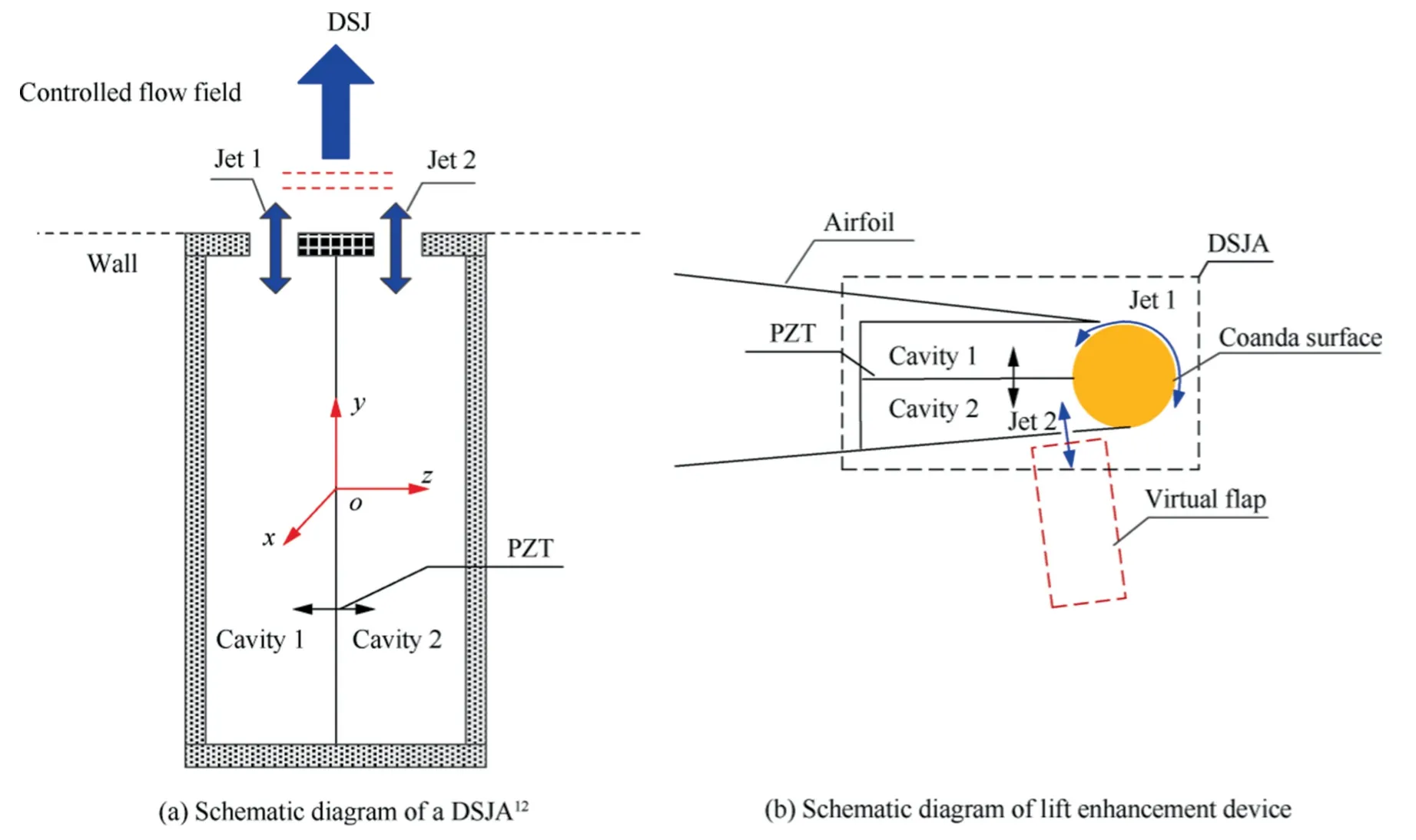
Fig.1 Configuration of new type of lift enhancement device.
The airfoil chosen in this calculation is NACA0015 airfoil.The airfoil is 300 mm in the chord length(c=300 mm).Fig.2 shows the details of grids.About 9%of the chord length at the trailing edge was modified.The ratio of Coanda radius (r) to chord length is 1.6%(r/c=1.6%).The upper and lower slots were arranged on the trailing edge of the airfoil.The ratio of slot height (h) to chord length is 1‰ (h/c=1‰).The free flow velocity (U∞) is 12.17 m/s.The corresponding Reynolds number(Re)based on the chord length and the free flow velocity is 250000.In order to facilitate the grid drawing,the lower slot was arranged vertically.The boundary conditions of these two slots are both pressure inlets,which are given by User Defined Function (UDF) provided from Fluent code.The phases of the two jets are opposite to simulate the working condition of the PZT.The radius of the calculation area is about 45 times the chord length.Structural mesh with an O type topology is adopted.The grid height of the first layer in the boundary layer is about 1 × 10⁻⁵m.The grid height near the two slots is 2×10⁻⁶m.The wallY+is approximate 1.The total number of grids is about 450,000.

Fig.2 Computational mesh.
2.2.Calculation method
In the present simulation,the flow field was assumed to be described by the 2-D Unsteady Reynolds-Averaged Navier-Stokes (URANS) equations.All the calculations given here were obtained using the separated solver (SIMPLE) of Fluent code.The turbulence model adopted thek-ω SST model,which has good prediction performance on simulation of circulation control.14No slip wall for the airfoil and pressure far field for the outer border were set as the boundary conditions.A second-order upwind difference scheme and a second-order implicit scheme were chosen for spatial discretization and time advancement respectively.
2.3.Verification
In order to verify the accuracy of the numerical calculation method in this paper,a numerical simulation of the E0020 airfoil with a 0° angle of attack at the momentum coefficient of 0.047 in Ref.15 was carried out.As shown in Fig.3,the pressure coefficients(Cp)at the airfoil are basically consistent with the experimental data,which proves that the numerical calculation method used in this paper has good performance on simulation of CC.
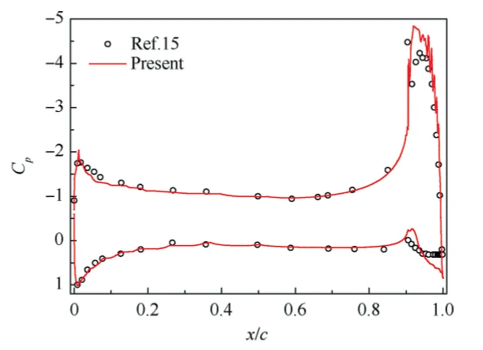
Fig.3 Verification results of E0020 airfoil.
For the NACA0015 airfoil,no excitation results of lift and drag coefficients at different angles of attack are shown in Fig.4.Three sets of data from other researches are presented for comparison.16–18It seems that good agreement is achieved in lift coefficients(CL)and drag coefficients(CD)as well as the stall angle (about 14°).Before the stall angle,drag coefficients and lift coefficients given from the present simulation and results cited from Ref.16 as well as Ref.17 are consistent.After the stall angle,though the drag coefficients achieve evident deviation,the drag coefficients increase as angles of attack increase.Compared with Pooya Kabiri’s experimental results,18the drag coefficients also have the same growing trend.In general,it is proved that the numerical calculation method used in this paper has good prediction performance on simulation of flow over a NACA0015 airfoil.
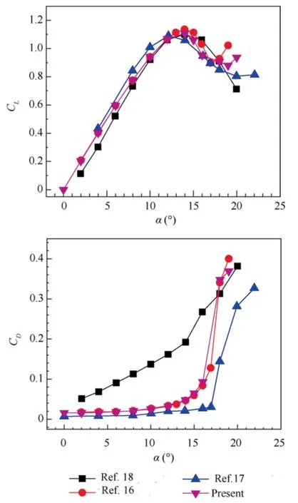
Fig.4 Verification results of NACA0015 airfoil(Re=250000).
3.Parameter definition
3.1.Momentum coefficient
The effect of CC is determined by the momentum rather than the mass of trailing-edge jets.In order to quantify the momentum in the control process,it is necessary to define a parameter as the basis for evaluating the control efficiency.The momentum coefficient is commonly used to characterize it,that is,Cμ.Its physical meaning is the ratio of jet intensity to free flow intensity.19The calculation formula is given as

where ρ∞andU∞are the density and velocity of incoming flow,respectively.Sis the plane area of the wing.And in 2D flow,the chord length (c) is often used to representS.Ijis the momentum of jets,and only the blowing strokes of jets are calculated forIj.The calculation formula used forIjis shown as

where ρjis the density of jets;Ajis the area of jet slot,which is often replaced by height (h) of the jet slot on a 2D airfoil;τ is the duration time of the blowing stroke.The jet velocity generally has the following sine function form:

whereUjis the maximum amplitude of jet velocity.Substituting Eq.(3) and Eq.(2) into Eq.(1),and considering the 2D flow of an airfoil,we can obtain the calculation formula for

3.2.Reduced frequency
In addition to momentum coefficient,the reduced frequencyF+(dimensionless characteristic frequency) is introduced to study the circulation control effect of the jet frequency.The calculation formula is given as

wherefandlare the driving frequency of a DSJA and the characteristic length,respectively.In the present study,the characteristic length used for Eq.(5) is the distance from the actuation location to the trailing edge.
3.3.Efficiency-cost ratio
Evaluating the control effect of lift enhancement only needs to pay attention to the lift increments after the control is applied,that is,ΔCL.However,considering that it is impossible to increase ΔCLby continually increasingCμin experimentsand engineering applications,the efficiency-cost ratio (ΔCL/Cμ)is introduced to evaluate the control efficiency.If the value of efficiency-cost ratio is relatively large,it means that good lift-enhancement effect can be achieved at a relatively low momentum coefficient,which is beneficial to actual operations and engineering applications.
4.Calculation results and discussion
4.1.Arrangement of working conditions
Table 1 shows the arrangement of working conditions of the simulation in this paper.The uncontrolled case is set as a basic reference.The focus of this paper is to study the effect of dual synthetic jet circulation control.In order to compare with the steady blowing jet control,the upper and lower trailing-edge steady blowing were used to control the flow over a NACA0015 airfoil firstly.Cμof upper and lower trailingedge steady blowing jets were set as 0.02.Secondly,the steady blowing jet was replaced by synthetic jet with the same momentum coefficients.The driving frequency of SJ was 40.6 Hz,whose correspondingF+was 0.025.Then,in order to simulate the working characteristics of the DSJA,the phases of two jets which eject from the upper and lower trailing-edge slots were set as opposite.Cμwas still set as 0.02.The driving frequencies of DSJ were set as 20.3 Hz,40.6 Hz,203 Hz,406 Hz and 812 Hz,which were used for studying the influence of reduced frequencies.The correspondingF+were 0.013,0.025,0.13,0.25 and 0.5,respectively.Besides,Cμof DSJ was increased to 0.04 to study the impact of momentum coefficient.In each of the above working conditions,the curves which show lift coefficients,drag coefficients,lift-to-drag ratios(CL/CD) and efficiency-cost ratios varying with the angles of attack were obtained.

Table 1 Working conditions.
4.2.Impact of different blowing methods
Fig.5 shows the lift coefficients,drag coefficients,lift-to-drag ratios and efficiency-cost ratios of different working conditions.The uncontrolled case is the basic reference.In the three cases with upper or lower trailing-edge synthetic jet and dual synthetic jet circulation control,F+was set as 0.025.Cμof the five controlled cases were all set as 0.02.
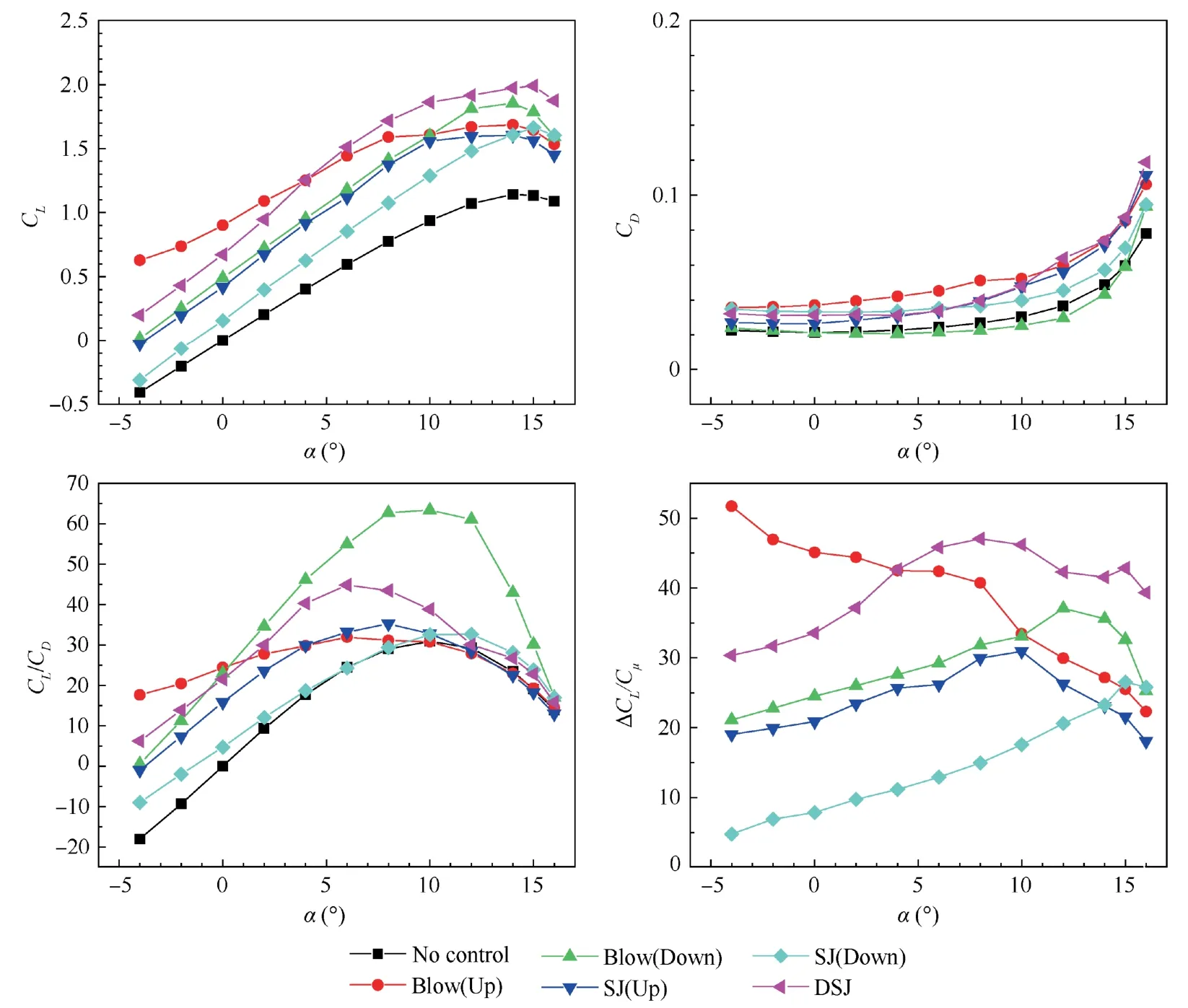
Fig.5 Aerodynamic coefficients of different working conditions (Cμ=0.02, F+=0.025).
As a classic and traditional circulation control method,the upper trailing-edge steady blowing circulation control achieves significant effect in lift enhancement.The maximum increment of lift coefficients at different angles of attack is about 1.03,which is approximately maximum lift coefficient in basic reference.It is worth noting that the relatively high efficiency-cost ratios occur in the case with upper trailing-edge steady blowing and lower trailing-edge steady blowing,indicating that the advantages and effectiveness of this traditional method are very significant.The same trend of lift enhancement is achieved when replacing the steady blowing jet at the upper trailing edge with synthetic jet,which proves that the decisive factor of circulation control is injecting momentum rather than injecting quality.Steady blowing jet and zero-mass jet injected from the lower trailing edge also get a significant lift-enhancement effect,which proves the feasibility of constructing virtual flaps by applying steady blowing jet or synthetic jet at the lower trailing edge.Besides,we can observe that,with either the lower trailing-edge jet or the upper trailing-edge jet,the increments of lift coefficients and the efficiency-cost ratios under the action of steady blowing are higher than those with synthetic jet at a same momentum coefficient.The reason for this phenomenon is that the synthetic jet or dual synthetic jet can be regarded as pulsed jet.And continuous Coanda effect will be achieved at trailing edge of the airfoil during the stroke of steady blowing.If pulsed jet is applied at trailing edge,continuous Coanda effect will be more or less weakened,which is not beneficial to increase lift.Among the five controlled cases,the two cases with the best lift-enhancement effect are the case with DSJ control and the case with upper trailing-edge steady blowing circulation control.At negative angles of attack and relatively small angles of attack (-4° to 4°),the upper trailing-edge steady blowing jet circulation control has better control effect on lift enhancement than DSJ control.At relatively large angles of attack (4° to 16°),applying DSJ control achieves higher increments in lift coefficients,and the maximum efficiency-cost ratio can reach 47.In other words,these two control methods have their own advantages at different AOAs.However,the lift-to-drag ratios in the case with DSJ control are always obviously higher than those with steady blowing control.This is because higher increments of drag coefficients are achieved when upper trailing-edge steady blowing is applied.In general,compared with upper trailing-edge blowing jet circulation control,the DSJ control has similar control effect and the same high efficiency in lift enhancement.It must be pointed out as a feature that DSJ control makes it easier to achieve higher lift-to-drag ratios,which proves that it is a potential method for lift enhancement.In the following,the impact ofCμandF+will be further studied.
4.3.Impact of reduced frequency
Fig.6 shows the impact of reduced frequency with DSJ control.Cμin Fig.6 is set as 0.02,andF+varies from 0.013 to 0.5.Firstly,compared with the uncontrolled case,the lift coefficients at different reduced frequencies are all greatly improved.When angles of attack are negative and zero,DSJ control produces positive lift coefficients.In terms of lift-todrag ratio,the lift-to-drag ratios at different reduced frequencies are also significantly increased,especially in these state from negative angles of attack to small angles of attack.The minimum increment of lift coefficients reaches 0.41,which proves that the DSJ control can achieve relatively good control effect at each reduced frequency.
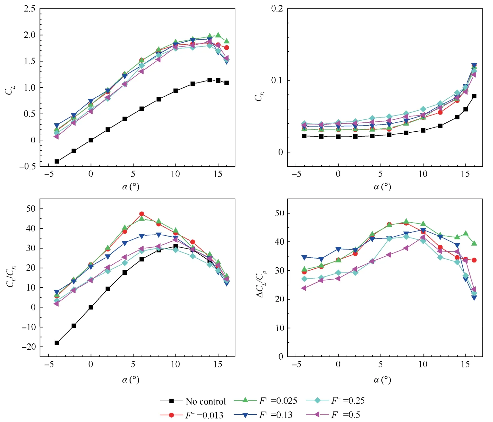
Fig.6 Impact of reduced frequency with DSJ control (Cμ=0.02).
As far as the increments of lift coefficients are concerned,the impact of reduced frequency on lift-enhancement effect seems unobvious.There is only a little difference among lift coefficients at these five reduced frequencies.However,from the perspective of lift-to-drag ratio,obviously higher lift-todrag ratios are achieved atF+of 0.013,0.025,and 0.13.It means that the optimal reduced frequency in this paper is in the range of 0.013 to 0.13.Besides,the maximum increments in lift coefficients and lift-to-drag ratios reach 0.94 and 26.1 as well as the maximum efficiency-cost ratio is about 47 atF+of 0.013.It can be concluded that DSJ control achieves high upper and lower limits at the same time,which has the potential for practical applications.
On the other hand,it was found that the reduced frequency has significant effect on the variation of lift and drag.9The main reason is that the reduced frequency can affect the vortex shedding.As a periodic phenomenon,vortex shedding is responsible for fluctuations in aerodynamic forces.20More importantly,the fluctuation of aerodynamic coefficients will affect the health of actual wing structure.In order to study the impact of reduced frequency on the fluctuation of aerodynamic coefficient,Fig.7 shows Power Spectral Density (PSD)of aerodynamic coefficients at different reduced frequency.The PSD of uncontrolled aerodynamic coefficients are also given as a basic reference.The abscissa represents the vortex shedding frequency,and the ordinate is the intensity of the PSD whose unit is in decibels.Note that all the spectra are normalized to decibel scale using the maximum of PSD which occurs atF+=0.5.It should be pointed out that the abscissa of Fig.7 is not dimensionless in order to compare the values of vortex shedding frequencies and excitation frequencies more clearly.
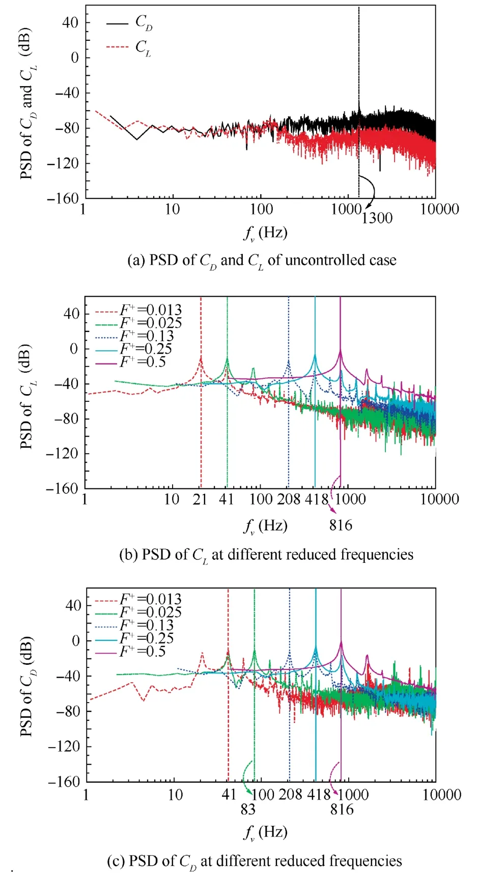
Fig.7 Power spectral density(PSD)of aerodynamic coefficients.
Ref.9 shows that after the trailing edge is chamfered,the vortex shedding frequency of the airfoil is related to the diameter of the rounded trailing edge.It can be seen from Fig.7 that when no control is applied,the peaks of PSD ofCDandCLare both located at about 1300 Hz,which is near the characteristic frequency of the airfoil calculated from the diameter of the rounded trailing edge as the characteristic length.After DSJ control is applied,it is obvious that the peak of PSD ofCLis located near the excitation frequency.Specifically,when the reduced frequencies are 0.013,0.025,0.13,0.25 and 0.5,the corresponding abscissas are 21 Hz,41 Hz,208 Hz,418 Hz and 816 Hz,respectively.The frequencies of lift fluctuation are very close to the excitation frequencies,indicating that the periodic excitation dominates the fluctuation ofCLat this time.As shown in Fig.7(c),when the reduced frequency is 0.013 and 0.025,the corresponding abscissas are 41 Hz and 83 Hz.Such values in Fig.7(c)are twice the corresponding frequency in the PSD ofCL,which is consistent with that reported by Pitital and Rajnish.9When the reduced frequencies are 0.13,0.25 and 0.5,the frequencies of drag fluctuation correspond to the excitation frequency.The above results indicate that the fluctuation of lift and drag is dominated by periodic excitation after DSJ is applied.And further observation reveals that their subharmonics can also be found at every increment of excitation frequency.
Fig.8 shows the comparison of the Root-Mean-Square(RMS)values of the fluctuating lift coefficients and fluctuating drag coefficients at α=10°.The abscissa represents different working conditions.Compared to the PSD results,the RMS value can intuitively indicate the degree of fluctuation.At this time,it can be clearly observed that when the reduced frequency is 0.13,the fluctuation of the lift coefficients and the drag coefficients is the smallest,which is beneficial to the safety of the wing structure in actual engineering.In general,the DSJ control achieves good performance on lift enhancement atF+of 0.013 when the fluctuation of lift and drag coefficients is also the smallest compared to the other reduced frequencies.
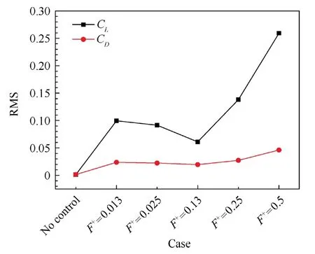
Fig.8 RMS values of fluctuating CL and CD.
4.4.Impact of momentum coefficient
Fig.9 shows impact of momentum coefficient with DSJ control.The reduced frequency chosen in Fig.7 is 0.013.The momentum coefficients of the two controlled cases in Fig.9 are 0.02 and 0.04,respectively.And the momentum coefficients of upper and lower trailing-edge jet are equal.Early studies3–5,21have proved that the stronger control effect will be achieved at higher momentum coefficients when steady or pulsed blowing jets are applied at upper trailing edge.As DSJ control is applied for lift enhancement atCμ=0.02,it is observed that the lift coefficients are greatly improved.When the momentum coefficient of DSJ is increased from 0.02 to 0.04,both the lift coefficients and the drag coefficients increase significantly.In terms of lift-to-drag ratio,at negative angles of attack,the lift-drag ratios of NACA0015 airfoil atCμ=0.02 are higher than those atCμ=0.04,which should be more attributable to the fact that the drag coefficients at negative angles of attack have not increased significantly.However,when the angle of attack exceeds 0°,lift-drag ratios atCμ=0.02 are higher.In terms of efficiency-cost ratio,the efficiency-cost ratios atCμ=0.02 are significantly higher than those atCμ=0.04.In practical applications,lift increments,energy consumption and efficiency should be considered in an overall way.
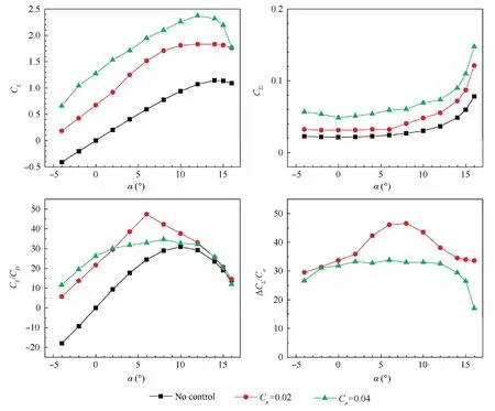
Fig.9 Impact of momentum coefficient with DSJ control.
4.5.Characteristics of flow fields
In this section,both the contours of Mach number (Ma)around the entire airfoil and the contours ofMaat the trailing edge of the airfoil in different cases are given to explain the control mechanism of the DSJ circulation control proposed in this paper.And the streamlines are drawn on these contours.The angle of attack chosen here is at 10°.It should be pointed out that all the following contours have been displayed within the same scale.In order to keep up with aerodynamic results,the reduced frequency of cases chosen here is 0.013.In these cases with DSJ control,the contours are drawn based on phase-averaged results.Each cycle is divided into 8 moments.
Fig.10(a) shows the contour ofMain the uncontrolled case.As shown in Fig.10(a),at an angle of attack of 10°,flow separation has not yet occurred on the upper trailing-edge surface of the airfoil.A large part of the low-velocity zone and two obvious separation bubbles occur downstream of the trailing edge.As the angle of attack continues to increase,the separation bubbles will gradually appear on the upper trailingedge surface of the airfoil.
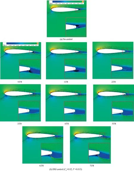
Fig.10 Contours of Ma under uncontrolled condition and DSJ control (Cμ=0.02, F+=0.013).
Fig.10(b) shows the contours ofMaat different phases with the DSJ control(Cμ=0.02,F+=0.013),whereinTrepresents the period of one cycle.Under this working condition,the blowing jet and suction jet eject from the upper and lower trailing-edge slots with an anti-phase state.At the phase of 1T/8,the upper or lower trailing-edge jet has just entered the blowing or suction stroke.Although the jet velocity has not yet reached the peak value,the velocities near the upper trailing edge are improved to varying degrees.The Coanda effect begins to be formed and the upper jet is produced to attach on the Coanda surface.At this time,the streamlines near the upper trailing-edge surface deflect toward the Coanda surface,which is classified into Coanda deflection in this paper.The attached jet flows downstream along the Coanda surface,then accelerates the downstream velocities on the Coanda surface,and induces that the downstream flow-separated area near the upper trailing edge becomes a flow-attached area.In the meantime,the separation bubble near the upper trailing edge disappears,with the area of the low-velocity zone in the near wake reduced.In addition,it is observed from the flow field around the entire airfoil that the position of stagnation points at the leading edge and trailing edge is changed after DSJ control is applied.Under the action of the upper trailing-edge jet,the momentum in the boundary layer near the trailing edge increases significantly,which causes the position of forward stagnation point and rear stagnation point to move down obviously.The moving of the forward stagnation point will also cause the leading-edge flow to separate more easily,which induces the stall angle of attack to advance slightly under the action of CC.
Compared with early studies3–5which focus on upper steady blowing jet circulation control,the obvious difference is that the synchronous jets which eject from upper and lower trailing-edge slots can be regarded as a kind of relay effect.The suction stroke of lower trailing-edge jet tends to make the streamlines approach the lower trailing-edge surface at the phase of 2T/8 when the velocities of low trailing-edge suction jet are relatively large.However,the deflection of upper trailing-edge jet is dominated at the phase of 3T/8.It indicates that the combination of upper trailing-edge blowing stroke and lower trailing-edge suction stroke has not weakened the control effect.On the contrary,the Coanda effect is more obvious.In other words,the suction stroke of lower trailing-edge jet strengthens the attachment and deflection of upper trailing-edge jet,which is beneficial to increase lift.Under the action of relay effect,the Coanda effect is obvious within the phases from 2T/8 to 3T/8,and the angle of deflection is about 180°.In the meantime,the deflection of attached jet is greater than that given in Ref.22 at a momentum coefficient of 0.04,which proves that the DSJ control achieves good performance.
At the phase of 4T/8,the lower trailing-edge jet is going to be at blowing stroke.Within the phases from 5T/8 to 7T/8,it is observed that the streamlines near the lower trailing-edge surface deflect downward significantly under the action of lower trailing-edge jet,which is very similar to the deflection of streamlines under the control of a flap.21,23Such phenomenon is defined as flap-like deflection in this paper,which creates more intuitive action of a virtual flap.Besides,an obvious low-velocity zone appears near the lower trailing edge of the airfoil,which is beneficial to provide positive pressure on upper trailing-edge surface.It is important to emphasize that under the suction stroke of the upper trailing-edge jet,the velocities of the fluid near the upper trailing edge are still accelerated,and the streamlines tend to deflect downward.Obviously,the deflection is not as significant as Coanda deflection produced by blowing stroke of upper trailing-edge jet.However,the jets which have deflected downward tend to merge with the lower trailing-edge jet,indicating that the suction stroke of upper trailing-edge jet contributes to the deflection of streamlines near the lower trailing edge.In other words,the flap-like deflection near the lower trailing edge is strengthened.In general,the upper and lower trailing-edge jet whose phases are opposite have significant relay effect at different moments,which strengthens the circulation control effect.The deflection of the streamlines can be seen more clearly from the entire flow field.Such deflection is the combined effect of the Coanda deflection and the flap-like deflection.Compared with the control effect using flaps in Ref.23,the combined deflection effect of the streamline is also very similar.
Compared with two independent anti-phase jets produced by two synthetic jet actuators,the upper trailing-edge jet and lower trailing-edge jet produced by a DSJA only use one PZT diaphragm to achieve the compression of two cavities,thereby generating two anti-phase jets at each phase of one cycle.It can be seen that the most intuitive advantage of DSJ circulation control is the higher energy utilization.
Fig.11 shows the contours ofMaat different phases with the DSJ control (Cμ=0.04,F+=0.013).Compared with contours atCμof 0.02,the flow fields at different moments change obviously.From the perspective of the entire flow field,it is observed that the degree of deflection is greater than that atCμof 0.02 andF+of 0.013.The position that streamlines begin to deflect at the lower trailing edge is also advanced.When the upper trailing-edge jet is at the blowing stroke,the lower trailing-edge suction stroke has more obvious relay effect on the Coanda deflection of upper trailing-edge jet.The overall deflection of streamlines at the phase of 3T/8 is more obvious especially near the lower trailing edge.As the lower trailing-edge jet enters the blowing stroke,the lower trailing-edge jet deflects upstream,which is with opposite direction compared with the case atCμof 0.02.Such phenomenon indicates that the blowing stroke of upper jet can affect the direction of deflection at the lower trailing edge ifCμis relatively large,which can also be regarded as another way of relay effect.With the increase of jet velocity,the angle of deflection increases to about 210°.The separation point of deflected jet locates at the lower trailing-edge surface instead of Coanda surface.And the position where streamlines begin to deflect near the lower surface is closer upstream than that in another case.This is equivalent to the fact that increasing the deflection angle of a flap can improve the lift and drag at the same time,which is in good agreement with the aerodynamic results in Fig.9.
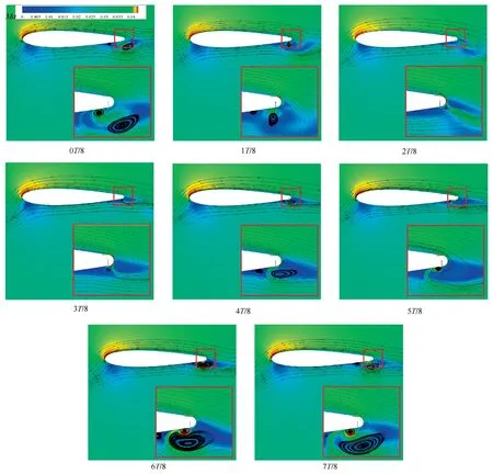
Fig.11 Contours of Ma under DSJ control (Cμ=0.04, F+=0.013).
Fig.12 shows the contours ofMaat different phases with the DSJ control (Cμ=0.02,F+=0.5).Compared with the case withF+of 0.013,the obvious difference is the angle of deflection.As the reduced frequency increases from 0.013 to 0.5,the maximum angle of deflection on the Coanda surface is about 120°at the phase of 3T/8,which is significantly smaller than 150° in the case withF+of 0.013.There are also differences in the attachment morphology of the upper jet on the Coanda surface.When the reduced frequency is low,the upper trailing-edge jet attaches to the Coanda surface and the peak velocities of deflected jets are continuous.As the reduced frequency increases to 0.5,the conversion of the blowing and suction stroke is more frequent.When the deflection angle of upper jet has not reached 120°,the upper trailing-edge jet begins to enter the suction stroke,which results in the fact that the peak velocities of deflected jets are not continuous.Obviously,such a phenomenon is not conducive to the formation of the continuous Coanda effect with a large angle of deflection.In other words,the effect of Coanda deflection is suppressed.It is observed that discontinuous peak velocities of deflected jets also appear as the lower trailing-edge jet is blowing stroke,which leads to the decline in control effect of flaplike deflection.In general,at higher reduced frequencies,the Coanda deflection of upper trailing-edge jet and the flap-like deflection of lower trailing-edge jet are not as obvious as those at lower reduced frequencies,which affects the control effect for lift enhancement.
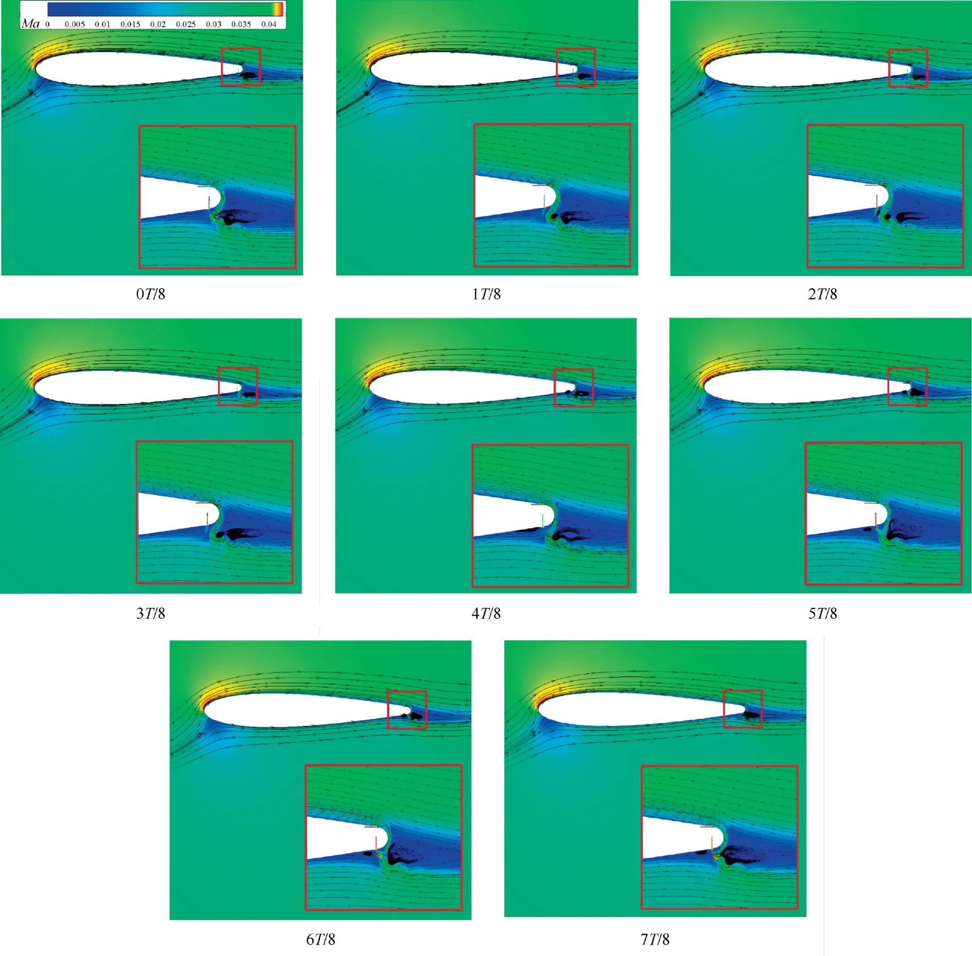
Fig.12 Contours of Ma under DSJ control (Cμ=0.02, F+=0.5).
5.Conclusions and prospects
(1) The circulation control method based on DSJ has good performance in lift enhancement.The upper trailingedge jet and lower trailing-edge jet produced by a DSJA only use one PZT diaphragm to generate two anti-phase jets at each phase of one cycle,indicating that the most intuitive advantage of DSJ circulation control is higher energy utilization.
(2) The control effect of DSJ circulation control is closely related to momentum coefficient (Cμ) and reduced frequency(F+).With the increase of the reduced frequency(F+=0.013 to 0.5),the control effect is slightly reduced at higher reduced frequencies,but the increments in lift coefficient atF+=0.5 is still very significant compared with uncontrolled case.WithCμincreasing from 0.02 to 0.04,the increments in lift coefficients at different angles of attack are improved obviously.But the efficiency-cost ratio atCμof 0.02 is significantly higher.The reduced frequency also has significant effect on fluctuation of lift and drag.AtF+of 0.13,the amplitude of aerodynamics fluctuation is relatively small.
(3) Under the control of DSJ,the anti-phase jets from upper trailing-edge slot and lower trailing-edge slot achieve relay effect,which is conducive to enhancing lift coefficients.The suction stroke of the lower trailing-edge jet can strengthen the Coanda effect of the upper trailingedge jet.And the upper trailing-edge jet which has deflected downward tends to merge with the lower trailing-edge jet,which contributes to the deflection of streamlines near the lower trailing edge.
(4) The zero-mass DSJ circulation control has the advantages of good control effect on lift enhancement and high efficiency-cost ratio.The lift-to-drag ratios under the action of DSJ control are also relatively high.It is a potential method of circulation control.In practical applications,the appropriate momentum coefficient should be comprehensively selected from the aspects of lift increments,energy consumption and efficiency.The selection of the reduced frequency should be based on the fluctuation of aerodynamic forces and optimal driving frequency of a DSJA.
Declaration of Competing Interest
The authors declare that they have no known competing financial interests or personal relationships that could have appeared to influence the work reported in this paper.
Acknowledgements
This study was co-supported by the National Natural Science Foundation of China (Nos.11972369 and 11872374) and the Youth Science and Technology Innovation Award funded project of National University of Defense Technology,China(434517314).
 CHINESE JOURNAL OF AERONAUTICS2022年12期
- CHINESE JOURNAL OF AERONAUTICS的其它文章
- Control and utilization of range-dependent beampattern with waveform diverse array radars
- Airside pressure drop characteristics of three analogous serpentine tube heat exchangers considering heat transfer for aero-engine cooling
- Numerical analysis of deflection control of a gas plasma jet based on magnetohydrodynamic staggered electrode configuration
- Neural network-based model predictive control with fuzzy-SQP optimization for direct thrust control of turbofan engine
- Method for utilizing PIV to investigate high curvature and acceleration boundary layer flows around the compressor blade leading edge
- Experimental investigation of expansion effect on shock wave boundary layer interaction near a compression ramp
