A 3D CFD simulation of oil spray-collection and delivery process in an aeroengine inter-shaft bearing
Donglei ZHU, Guoding CHEN, Ynjun LI,, Choyng ZHANG,Lin WANG,*
a School of Mechanical Engineering, Northwestern Polytechnical University, Xi’an 710072, China
b China Gas Turbine Establishment, Chengdu 610500, China
KEYWORDS
Abstract Under-race lubrication applied to the inter-shaft bearing of aeroengine is characterized by spray oil collection and oil delivery to the bearing via flow-path structure. Droplet splashing induced by the collision between spray oil and the scoop as well as oil flowing characteristics in the flow-path influence bearing lubrication efficiency. In previous investigations, the spray oil collection and oil delivery analysis were separated,and the effect of droplet splashing on bearing lubrication efficiency was not considered. Moreover, time-varying characteristics of oil delivered to the bearing were not accounted for.This is caused by time variations of the circumferential position of rollers and under-race feed holes. To overcome these limitations, a numerical model which integrates the spray oil collection and oil delivery analysis is proposed in this paper. The model is embedded with the function of calculating the flow rate of splashing droplets and analyzing time-varying characteristics of the oil fed to the bearing. Furthermore, the numerical model is validated by experimental investigation. The proposed numerical model facilitates the accurate calculation of bearing lubrication efficiency as well as the design of an efficient lubrication structure.©2021 Chinese Society of Aeronautics and Astronautics.Production and hosting by Elsevier Ltd.This is an open access article under the CC BY-NC-ND license(http://creativecommons.org/licenses/by-nc-nd/4.0/).
1. Introduction
Under-race lubrication of the shaft-supporting bearing in aeroengine is twofold with oil spray-collection and oil delivery to the bearing.Due to the high rotational speed of aeroengine shafts and consequent motion of bearing elements,the proportion of spray oil captured by the scoop is not adequate. Furthermore, it is difficult to deliver oil to the bearing via under-race feed holes. Therefore, the design of efficient bearing lubrication structure presents a significant challenge.Among the bearings that aeroengine shafts are supported on,the inter-shaft bearing particularly requires sufficient lubricating to ensure steady operating and capability of high-pressure(HP)and low-pressure (LP) shafts. However,severe operating conditions emanating from counter-rotating of HP-LP shafts and the complexity of under-race lubrication structure may lead to inadequate lubricating and consequent bearing failure.Hence, the analysis of oil spray-collection and delivery in an aeroengine inter-shaft bearing is valuable in engineering applications and academically significant.
Many investigations have been devoted to the inter-shaft bearing under-race lubrication. Xu et al.computationally investigated the flow phenomena within scoop structure of inter-shaft bearing. The authors observed that splashing droplets escaped from the scoop via rotating air through an oil retaining dam.Consequently,the authors proposed to improve the scoop structure which would prevent residence droplets from escaping. Lifound that inter-shaft bearing lubrication efficiency improved with the increasing size of the flow-path,which simultaneously reduced the strength of the lubrication structure.The author further presented optimizing lubrication structure to make compromise between lubrication efficiency and structural strength.
The counter-rotation of HP-LP shafts as well as the complexity of the lubrication structure increase the difficulty of conducting bearing under-race lubrication experiments. Consequently, experimental investigations of inter-shaft bearing under-race lubrication are rarely seen. However, experimental studies concerning about the oil spray-collection process of regular bearings can be found.Fisher et al.designed a scoop with equidistant blades.The spray oil is either splashed or captured by scoop following its collision with the blade tip. The captured oil is further fed to the bearing through under-race feed holes. To improve the scoop catch efficiency, Dins and McDonagh et al.modified the blade curve of the scoop.Based on the improved scoop structure, Cageao et al.carried out oil spray-collection experiments and found that the oil loss in spray-collection process included both splashing droplets and the oil ejected outwards from the scoop due to centrifugal force. In addition, observation showed that jet oil grew linearly in time after being sliced by the rotating scoop blades. To minimize the oil loss within the spray-collection process,Cageao investigated the effect of jet velocity on scoop capture efficiency.The experiment implemented by Lee et al.demonstrated that scoop catch efficiency decreased significantly with an increase in the jet flow rate. Based on a similar apparatus, Krug et al.further found that catch efficiency decreased with the increasing diameter of nozzle or impingement angle.
Due to relatively expensive experimental investigations and the gap between experimental and aeroengine representative operating conditions,computational approaches are employed in oil spray-collection analysis of regular bearings.With Computational Fluid Dynamics (CFD) and Smoothed Particle Hydrodynamics (SPH), Korsukova et al.established two-dimensional(2D)numerical models to calculate the scoop catch efficiency. The calculation results with CFD and SPH demonstrated good qualitative agreement. Moreover, typical flow phenomena revealed in the experimentwere well captured by CFD as well as SPH.By employing CFD,Prabhakar et al.demonstrated that a blunter scoop blade tip led to an improvement in catch efficiency due to reduced vortex shedding. Simmons et al.proposed the intermittent spray oil method to eliminate splashing droplets arising from the collision between the spray oil and scoop blade tip. The computational results validated the improvement of catch efficiency due to the intermittent oil spraying.However, the calculated catch efficiency was not well-fitting with the experimental data,which was attributed to the limitations of a 2D numerical model. With the CFD method, Lyu et al.investigated the effect of impingement angle and oil scoop radius on catch efficiency, then proposed optimal structural parameters. Qin et al.designed a novel curved blade oil scoop theoretically and calculated the scoop catch efficiency by CFD simulation.The authors found that the catch efficiency of novel curved blade oil scoop was improved compared to the traditional scoop.
Previously mentioned investigations demonstrate that some limitations to the research on under-race lubrication of intershaft bearing are present.First,an integrated numerical model,which integrates oil spray-collection and oil delivery analysis,has not been established.Second,computational investigations of oil spray-collection are based on 2D scoop geometry.Hence, the effect of droplet splashing on bearing lubrication efficiency,which immensely affects the fidelity of the computational model, is not considered. Third, numerical simulations of oil delivery are single-phased and steady-state,thus ignoring the time-varying characteristic of oil delivery to the bearing.These limitations impede engineering applications of the existing under-race lubrication research.
Based on three-dimensional oil spray-collection and delivery structure (lubrication structure), droplet splashing status and time-varying characteristics of oil delivery to the bearing are investigated in this paper. Furthermore,the integrated numerical model which comprises the oil spray-collection and delivery analysis is proposed. The accuracy of the numerical model is validated via bearing underrace lubrication experiment. In addition, the effects of structural and operational parameters on bearing lubrication efficiency are obtained by the numerical model. These results provide insight into the design of efficient lubrication structure.
2. Under-race lubrication structure of aeroengine inter-shaft bearing
As shown in Fig. 1, the under-race lubrication structure of inter-shaft bearing is composed of oil spray-collection and oil delivery structure. Part of the spray oil is captured by the scoop holes, while the other part is either deposited as the oil filmon scoop wall or splashed as droplets. The deposited oil film enters the scoop holes due to centrifugal force,whereas splashing droplets escape from the scoop due to rotating airflow.
The oil captured by the scoop flows into the inter-shaft chamber via holes in the LP shaft.This oil mixes with pressurized air which is blown from labyrinth seal. Thus, oil/air twophase flow is generated within the chamber. The majority of the oil within the chamber is fed to bearing elements through under-race feed holes,while the rest of it leaks out of the chamber from the labyrinth and the gap seal. Due to the timevarying circumferential position of rollers and under-race feed holes, the amount of oil delivered to the bearing varies with time.
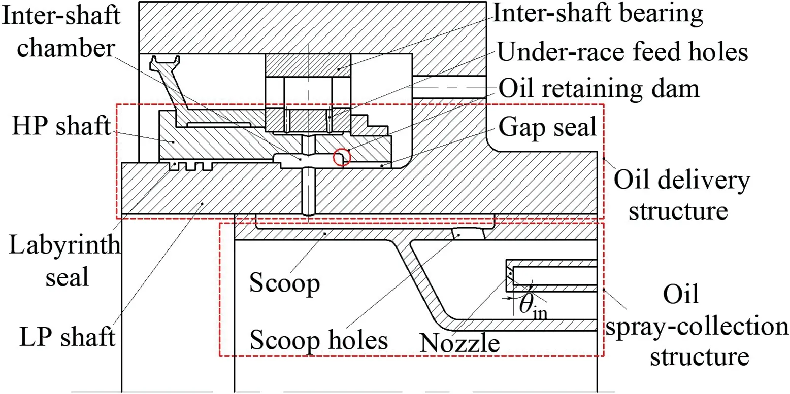
Fig.1 Under-race lubrication structure of aeroengine inter-shaft bearing.
3. Key techniques in the analysis of bearing under-race lubrication
3.1. Analysis of time-varying oil delivery to inter-shaft bearing
This analysis is targeted to reveal the regularity of time-varying oil flow status within under-race feed holes. Based on the regularity, transient boundary conditions on the outlet of underrace feed holes are obtained. Based on the boundary conditions, the numerical simulation model of oil spray-collection and delivery is established.
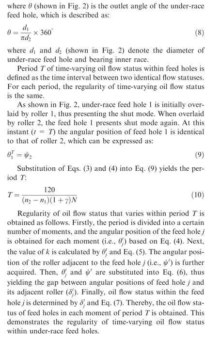
During the operating of inter-shaft bearing, when the circumferential position of rollers and under-race feed holes overlap with each other,lubricant oil is hardly discharged from the feed holes due to the obstruction of rollers. At this instant oil flow status within feed holes is defined as‘‘shut”mode.On the contrary,the‘‘open”mode emerges at the moment when there is no overlapping in the position of rollers and feed holes.Lastly, the ‘‘half-shut” mode represents a flow status between open and shut modes.
For the analysis convenience, rollers are regarded as fixed based on the relative motion principle. The under-race feed holes rotate with the speed(n-n)relative to rollers.Parameters nand ndenote the rotational speed of feed holes (i.e.,bearing inner race or HP shaft) and rollers. Parameter nin pure rolling condition is given by
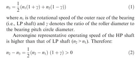
A schematic illustration of the initial circumferential position of rollers and under-race feed holes is shown in Fig. 2.Within the figure, clockwise orientation is defined as positive.Eq. (2) indicates that under-race feed holes rotate in a clockwise direction relative to the rollers.
As shown in Fig. 2, inter-shaft bearing initially operates when under-race feed hole 1 is overlaid by roller 1.The angular position of roller 1 is taken as the angular coordinate origin(0°). Consequently, the angular position of roller i(i = 1,2,...,N) is regarded stationary:
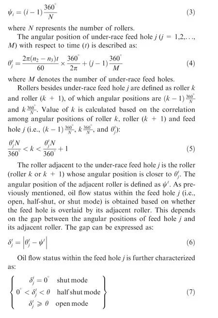
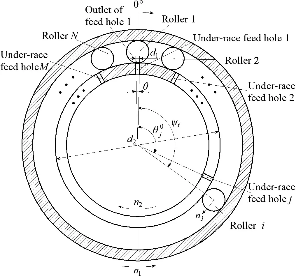
Fig. 2 Initial circumferential position of rollers and under-race feed holes (t = 0 s).
3.2. Calculation of uncaptured droplet flow rate
As illustrated in Fig. 3, the oil which is not captured by the scoop consists of two parts.One is the splashing droplets emanating from the collision between the spray oil and scoop wall.The other part is the droplets disengaged from the scoop wall film due to the shearing force of the rotating airflow. Due to the coalescence and depression of uncaptured droplets, the number and position of those droplets vary with time. Consequently, it is difficult to calculate the flow rate of uncaptured droplets, which quantitatively presents the amount of oil lost in the spray-collection process.
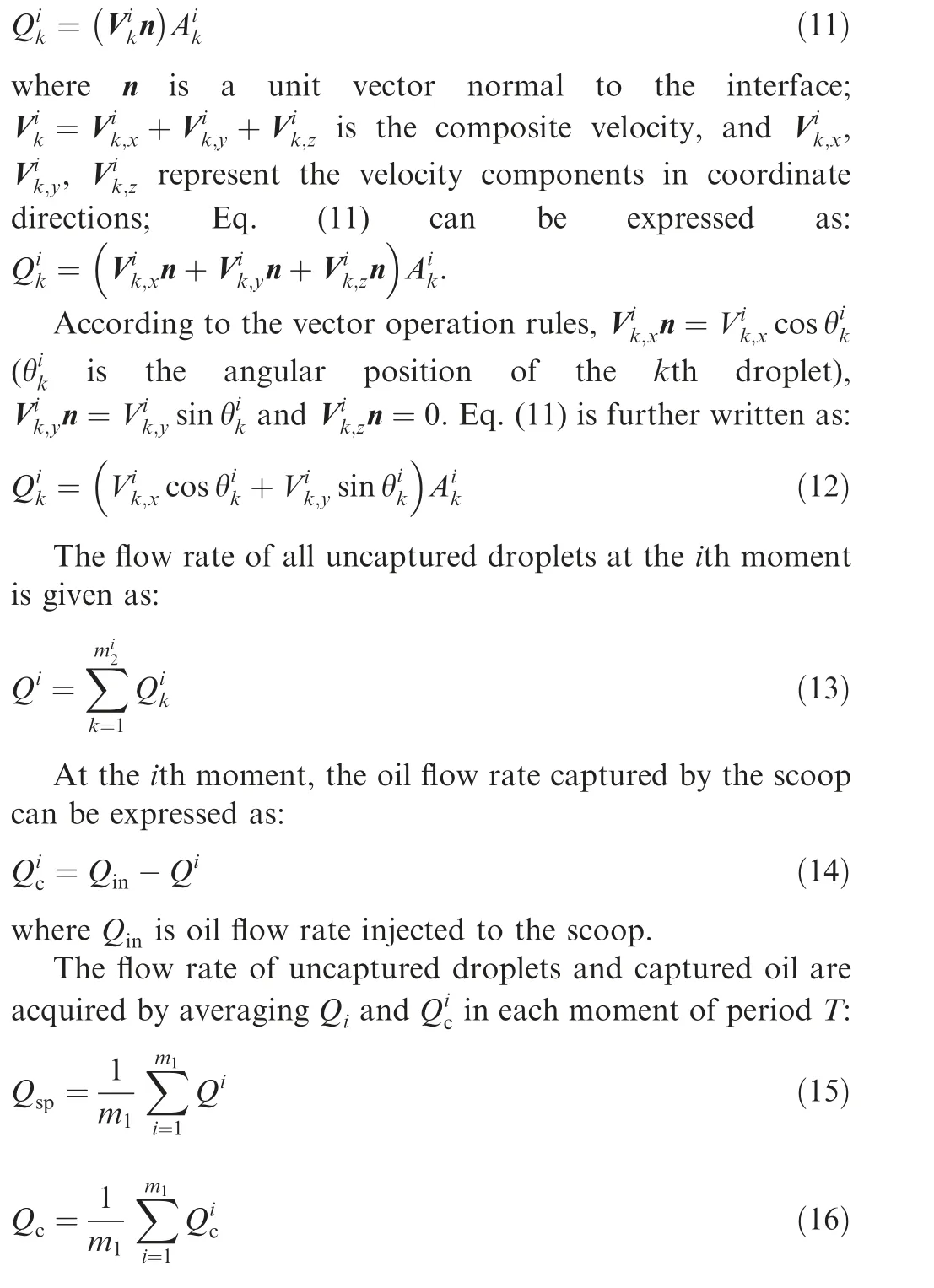
To obtain the flow rate of uncaptured droplets,an interface located between the nozzle and scoop wall is established. At each instant, the number of uncaptured droplets within the interface is acquired by numerical simulation and iso-surface capture technique, where oil droplets can be tracked instantaneously. Interfacial area (arising from the droplet sliced by interface)and velocity of each droplet are obtained in the same way.Thus,flow rate of uncaptured droplets can be calculated.
The period T is equally divided into mmoments.At the ith moment,the number of uncaptured droplets through the interface is equal to m.Interfacial area and velocity of the kth droplet are Aand V, respectively. According to the theories of fluid mechanics,the flow rate of the kth droplet is described by
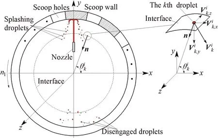
Fig. 3 Splashing and disengaged droplets in oil spray-collection process.
4. Numerical simulation of oil spray-collection and delivery
4.1. Fundamental equations of oil/air two-phase flow analysis
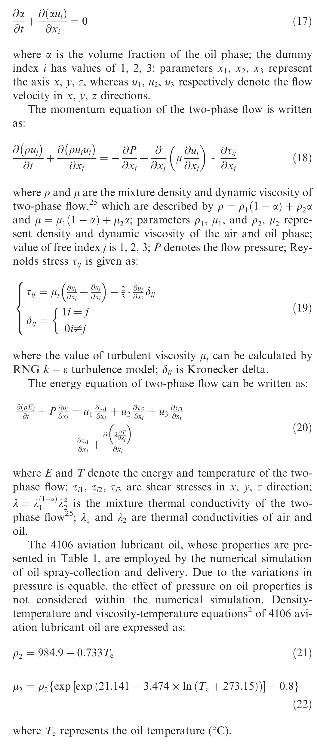
The continuity equation of oil/air two-phase flow is given as:
4.2. Numerical simulation model of oil spray-collection and delivery
The geometry of oil spray-collection and the delivery computational domain is illustrated in Fig. 4(a). In Fig. 4(b), the flowing boundaries of oil/air two-phase liquid are shown. The corresponding boundary conditions are provided in Table 2.Transient boundary conditions on the outlet of under-race feed holes are obtained from the regularity of time-varying oil flow status within the feed holes (shown in Section 3.1).When oil flow status is in the shut mode,the outlet velocity of under-race feed hole is set as zero;when oil flow status is open mode,the outlet pressure of under-race feed hole is the bearing chamber pressure; when oil flow status is half-shut mode, the open and shut parts of the feed hole outlet are obtained by the corresponding boundary conditions.

Fig. 4 Geometry of computational domain and flowing boundaries of liquid.
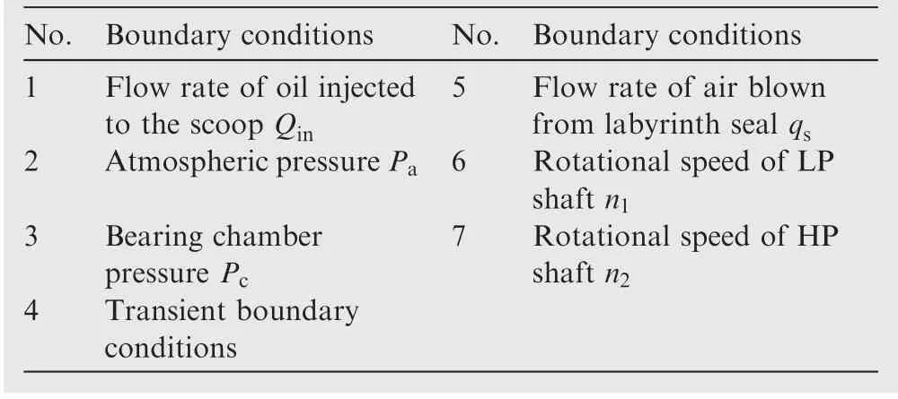
Table 2 Boundary conditions.

Table 1 Properties of 4106 aviation lubricant oil.
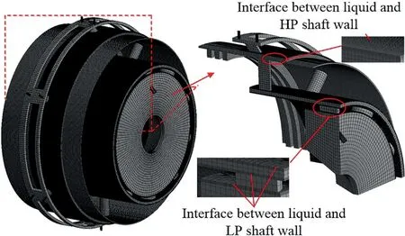
Fig. 5 Computational domain mesh and finer mesh region.
Computational domain mesh is illustrated in Fig. 5. In the near-wall region, a finer mesh is adopted to suit the requirements of the RNG k-ε turbulence model.
The flow chart of numerical simulation for oil spraycollection and delivery process is presented in Fig.6.To satisfy the numerical stability criterion (Courant-Friedrichs-Lewy condition, i.e., CFL condition), period T is equally divided into mmoments, and the time interval between adjacent moments is ensured (time step δt). The numerical stability criterion is described as:

where his the smallest cell size within the computation domain; udenotes the highest velocity of the liquid flow;Co represents the Courant number which is kept below 1 to minimize the computational errors.
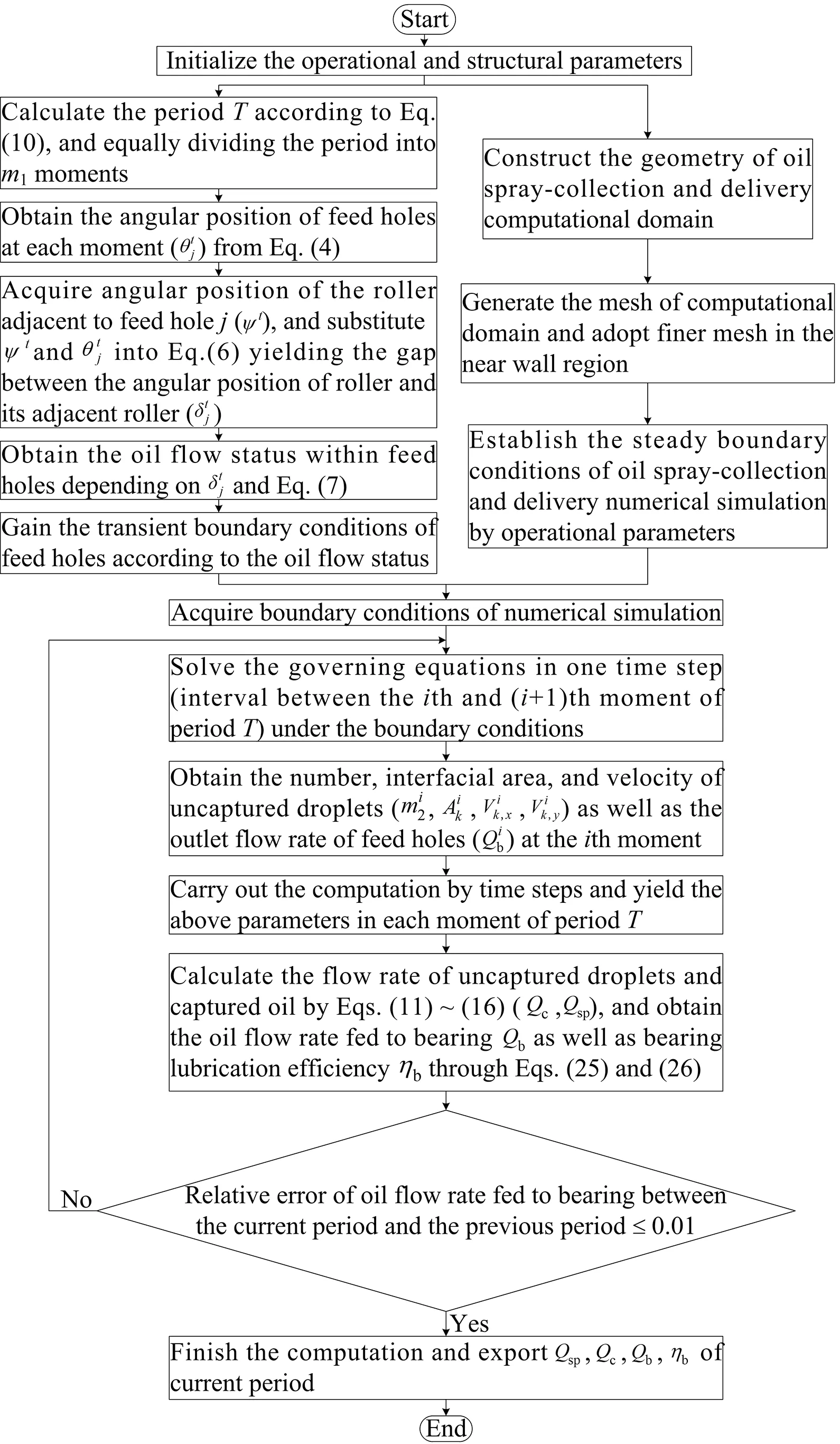
Fig. 6 Flow chart of numerical simulation.
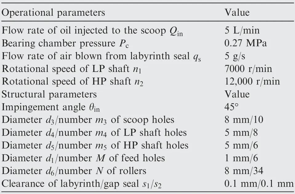
Table 3 Operational and structural parameters.

Table 4 Oil flow rate fed to bearing with four numbers of cells.
Continuity, momentum and energy equations (Eqs. (17),(18), and (20)) are solved by FLUENT. The Volume of Fluid(VOF)model is used to solve the volume fraction of oil phase.Pressure-Implicit with Splitting of Operators (PISO) is taken as the algorithm for solving the aforementioned equations,while Zwart-Gerber-Belamri cavitation model is activated to consider the effect of cavitation on oil spray-collection and delivery process.Over a single time step(δt=10s,calculated by Eq. (23)) computation, the oil temperature of each grid is substituted into Eqs. (21) and (22) and the oil properties of each grid are updated. Thus, the computation is carried out by time steps.The computation is completed once the solution has converged. The convergence criterion is defined when the relative error of oil flow rate fed to bearing between the current period T and the previous period is smaller than the certain permissible error (1%).
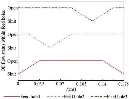
Fig. 7 Oil flow status of under-race feed holes 1, 2, and 3 with respect to time.
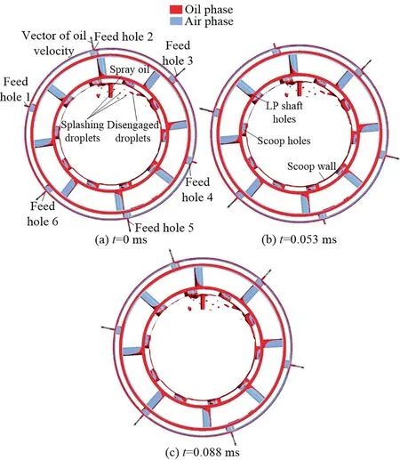
Fig. 8 Oil flow status at three moments of period T.
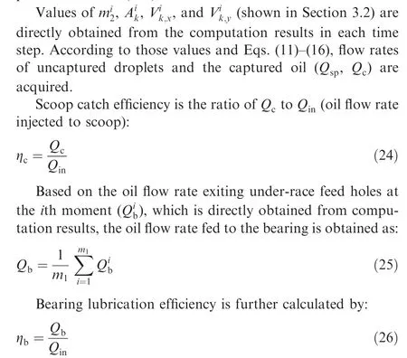
Based on the operational and structural parameters presented in Table 3, numerical simulations of oil spraycollection and delivery are implemented with 508,186,691,646,820,069 and 1,007,199 cells.In Table 4,the calculated oil flow rates fed to bearing Qand the relative errors of Qbetween two adjacent numbers of cells are presented. As can be seen, the relative error between 820,069 and 1,007,199 (1 million) cells is smaller than 1%. Thus, 1 million is taken as the standard cell number for the oil spray-collection and delivery simulation.
4.3. Numerical simulation of oil spray-collection and delivery
Operational and structural parameters adopted by the numerical simulation are presented in Table 3 with the counter rotating of HP and LP shafts. Based on the values of Table 3 and the numerical simulation model proposed in Section 4.2,numerical computation of oil spray-collection and delivery is conducted.
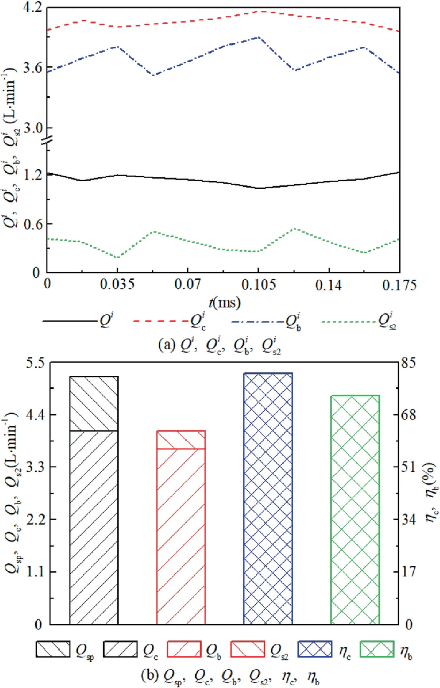
Fig. 9 Bearing lubrication parameters.
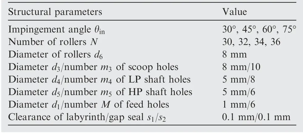
Table 5 Structural parameters.
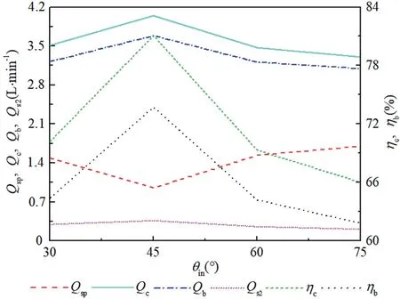
Fig. 10 Effect of θin on bearing lubrication properties.
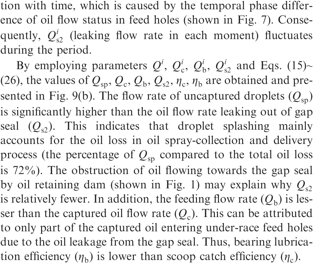
During the computation,period T is calculated as 0.175 ms and the regularity of time-varying oil flow status within underrace feed hole 1,2,and 3 is shown in Fig.7,where flow status of feed hole 4,5,and 6 is identical to that of feed hole 1,2,and 3. As can be seen, temporal phase difference exists in the oil flow status of those feed holes.
In Fig. 8, the oil flow status within oil spray-collection and delivery structure at the 0 ms(feed hole 1 and 4 are shut while the others are open),0.053 ms(feed hole 2 and 5 are shut while the others are open), and 0.088 ms (6 feed holes are open) are shown. At these three moments the oil enters the scoop holes as consequence of centrifugal force; droplets splash due to the interaction with scoop wall and droplets disengage from the wall film under the shear force of rotating air.In addition,with the counter-rotation of HP and LP shafts, the oil within scoop holes and LP shaft holes deposits on the left-side wall,while the oil in HP shaft holes accumulates at the right-side wall. Wall films within HP shaft holes enter under-race feed holes and further lubricate the bearing elements.

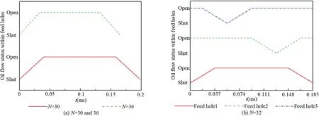
Fig. 11 Oil flow status in under-race feed holes with different roller numbers.
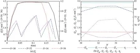
Fig. 12 Variation of Qib, Qsp, Qc, Qb, Qs2, ηc and ηb with N.
4.4. Influence of structural and operational parameters on bearing lubrication properties
4.4.1. Influence of structural parameters
As previously mentioned, droplet splashing mainly accounts for the oil loss in oil spray-collection and delivery process,and the amount of oil fed to the bearing is associated with oil flow status in under-race feed holes. To reduce the oil loss and improve oil flow rate fed to the bearing, the effects of impingement angle θand roller number N on bearing lubrication properties are investigated. θand N relate to droplets splashing and oil flow status in feed holes, respectively.
The adopted operational parameters are shown in Table 3.Structural parameters are provided in Table 5.
During the analysis of impingement angle (θ) influence,the number of rollers is 34 while other structural parameters are taken from Table 5. The period T is 0.175 ms and oil flow status of feed holes in each moment of the period are shown in Fig. 7.
In Fig.10,variations of Q,Q,Q,Q,η,and ηwith different impingement angles are shown. The flow rate of captured oil (Q) increases with the rise of impingement angle.After reaching the peak where impingement angle is 45°, Qdecreases with the further increase of the angle. The varying regularity of Q(flow rate of uncaptured droplets)is contrary to that of Q. This can be explained by the minimum interaction between the path of spray oil and the wall near scoop holes as the impingement angle is 45°. In such instance, the amount of splashing droplets emanating from the interaction is minimal compared to other angles. Consequently, the flow rate of uncaptured droplets (Q) is the lowest, while that of captured oil (Q) reaches the peak value.
According to Fig.10,varying regularity of Qand η(feeding flow rate and lubrication efficiency) with the impingement angle is identical to that of Q. The values of Qand ηreach the peak as impingement angle equals to 45°.

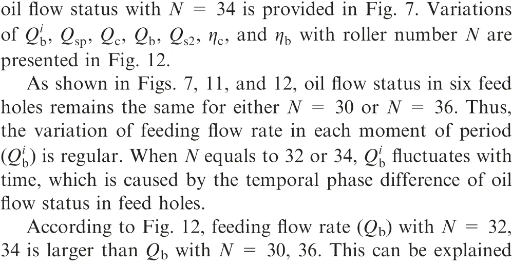
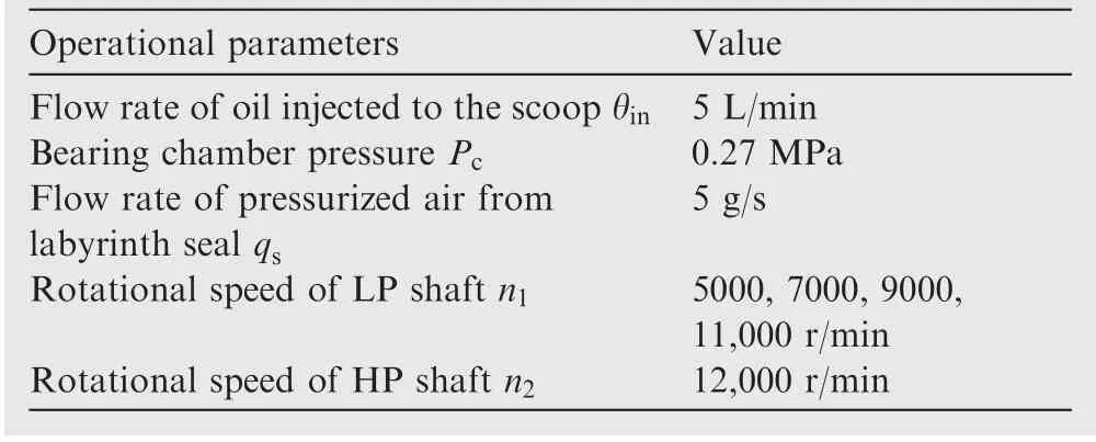
Table 6 Operational parameters.

Fig.13 Variation of Qib,Qsp,Qc,Qb,Qs2,ηc and ηb with n1 (HP and LP shafts counter-rotate).
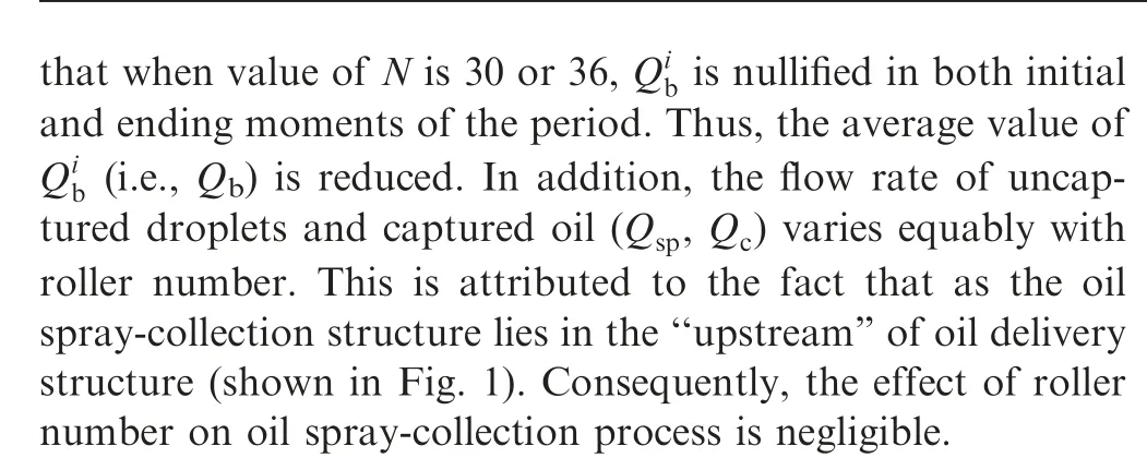
According to the impingement angle and roller number effect on bearing lubrication properties, it can be concluded that the combination of parameters θ= 45° and N = 34 can furthest reduce the oil loss in oil spray-collection and delivery process, as well as improve the bearing lubrication efficiency. Furthermore, when the rollers number is equal to 30 or 36 (the multiple of under-race feed holes number), bearing lubrication efficiency is lower than the efficiency with N = 32 or 34 (not the multiple of under-race feed holes number). Therefore, to improve the lubrication efficiency, the feed holes number is designed not being the multiple of the rollers number.
4.4.2. Influence of operational parameters
Based on the aeroengine type, HP and LP shafts are designed to counter-rotate or co-rotate.Under those two circumstances,the effect of LP shaft rotational speed on bearing lubrication properties is investigated. During the analysis, impingement angle and roller number are taken as 45° and 34. The remaining structural parameters are taken from Table 5.Operational parameters are provided in Table 6.
When rotational speed of LP shaft(n)is 5000,7000,9000,or 11,000 r/min,the period T is equal to 0.195,0.175,0.157,or 0.144 ms with the counter-rotation of HP and LP shafts. For the co-rotation of two shafts, the period T is equal to 0.474,0.663, 1.106, or 3.317 ms. It can be observed that the period T is shortened with an increase in nas HP and LP shafts counter-rotate, while being prolonged with the rise of nas two shafts co-rotate.
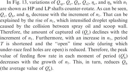
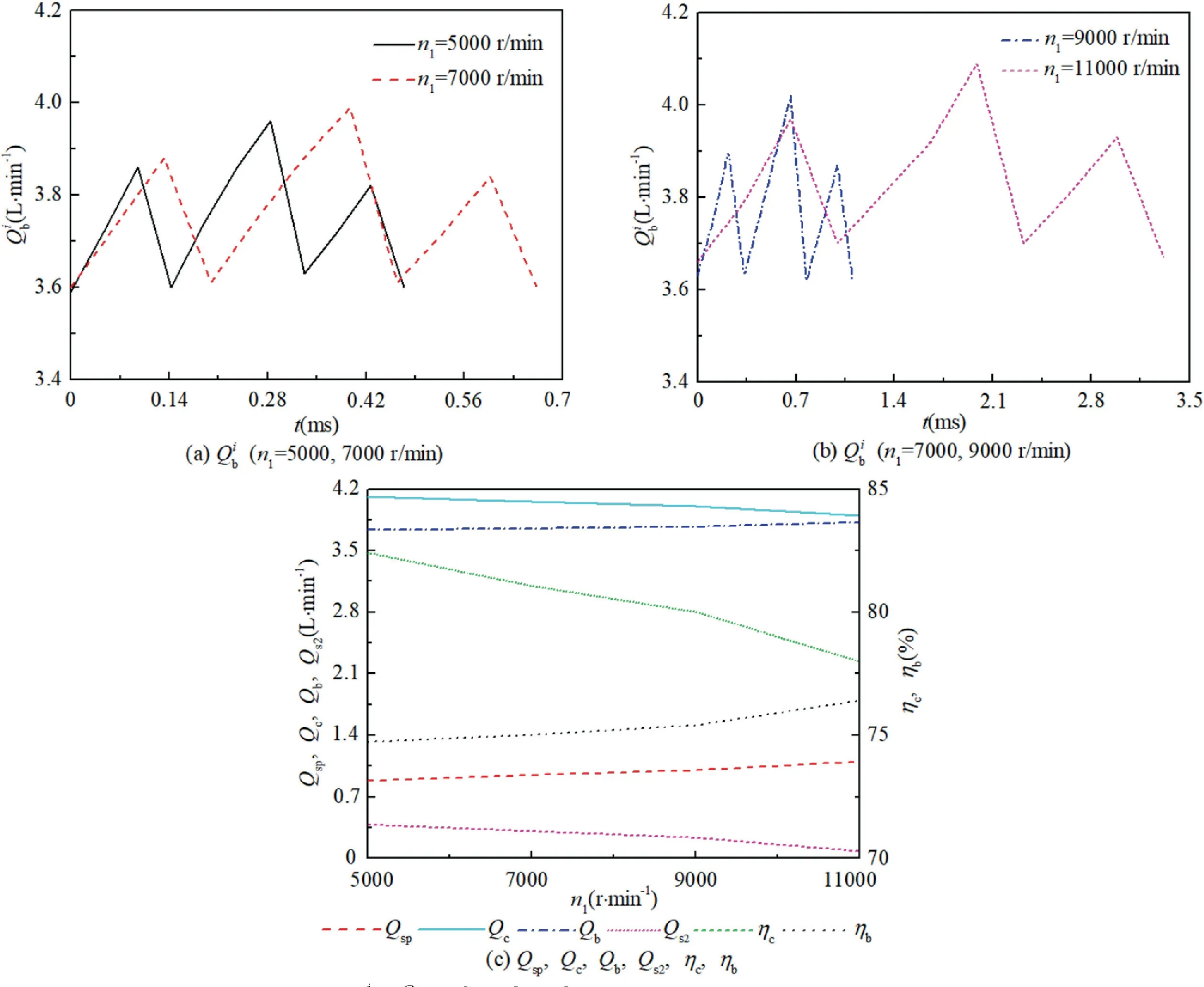
Fig. 14 Variation of Qib, Qsp, Qc, Qb, Qs2, ηc, ηb with n1 (HP and LP shafts co-rotate).
In Fig.14,variations of Q,Q,Q,Q,η,and ηwith nare shown as HP and LP shafts co-rotate. The variation regularity of Qwith nunder co-rotation condition is identical to that of counter-rotation condition. Moreover, as both period T and ‘‘open” time scale are prolonged with the increasing n, values of Qand ηincrease with the rise of n.
5. Experimental validation of the numerical simulation model
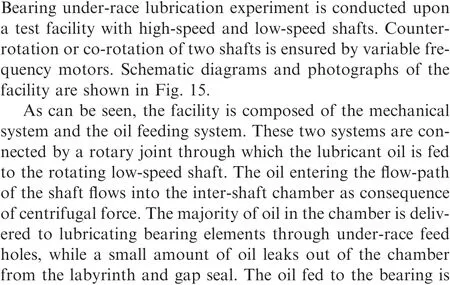
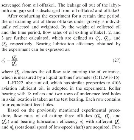
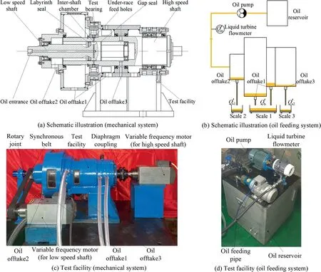
Fig. 15 Schematic illustration and photographs of test facility.
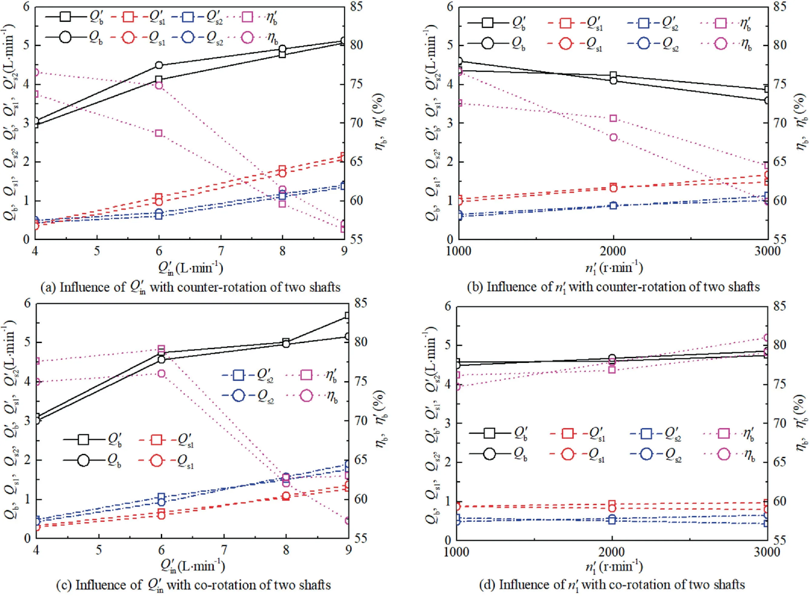
Fig. 16 Experimental and calculation results with different Q′in and n′1.
ther, based on experimental structure and operating conditions,the oil flow rate fed to the test bearing,oil flow rate leaking from labyrinth/gap seal, and bearing lubrication efficiency(Q,Q,Q,η)are obtained by numerical simulation method(shown in Section 4.3). The experimental and calculation results are illustrated in Fig. 16.
6. Conclusions
The conclusions of the paper are as follows:
(1) The oil loss within oil spray-collection and delivery process consists of uncaptured droplets and the leakage oil.The uncaptured droplets account for 72% of the total oil loss.
(2) Bearing lubrication efficiency increases with the growth of impingement angle. After reaching the peak value,lubrication efficiency decreases with a further increase in angle. When the rollers number N is equal to 30 or 36(the multiple of under-race feed holes number),bearing lubrication efficiency is lower than the efficiency with N=32 or 34 (not the multiple of under-race feed holes number).
(3) Bearing lubrication efficiency decreases with the increasing rotational speed of LP shaft as HP and LP shafts counter-rotate. When the two shafts co-rotate, bearing lubrication efficiency increase with the rise of rotational speed of LP shafts.
(4) Bearing lubrication efficiency obtained by numerical simulation demonstrates good agreement with the experimental results. The difference between calculation and experimental results is less than 10%.
(5) Some suggestions are provided to reduce the oil loss and enhance the bearing lubrication efficiency: (1) The impingement angle of nozzle is designed within the scope of 30°–60°. The angle corresponding to the highest efficiency is further determined numerically or experimentally; (2) For a specific bearing type, the number of under-race feed holes is designed not being the multiple of the rollers number.
The authors declare that they have no known competing financial interests or personal relationships that could have appeared to influence the work reported in this paper.
The work in this paper was supported by the National Science and Technology Major Project (No. J2019-III-0023-0067), the National Natural Science Foundation of China (No.51975475) and the Fundamental Research Funds for the Central Universities (No. 31020200503002).
 Chinese Journal of Aeronautics2022年9期
- Chinese Journal of Aeronautics的其它文章
- Effect of vortex dynamics and instability characteristics on the induced drag of trailing vortices
- Dynamic modeling and beating phenomenon analysis of space robots with continuum manipulators
- An effective crack position diagnosis method for the hollow shaft rotor system based on the convolutional neural network and deep metric learning
- A homogenization-planning-tracking method to solve cooperative autonomous motion control for heterogeneous carrier dispatch systems
- Static magnetic field analysis of hollow-cup motor model and bow-shaped permanent magnet design
- Adaptive modification of turbofan engine nonlinear model based on LSTM neural networks and hybrid optimization method
