Dynamic modeling and beating phenomenon analysis of space robots with continuum manipulators
Jinzho YANG, Hijun PENG, Jie ZHANG, Zhigng WU
a School of Aeronautics and Astronautics, Dalian University of Technology, Dalian 116024, China
b Department of Engineering Mechanics, Dalian University of Technology, Dalian 116024, China
c State Key Laboratory of Structural Analysis for Industrial Equipment, Dalian University of Technology, Dalian 116024, China
KEYWORDS Continuum manipulators;Dynamic model;Solar arrays;Space robots;Vibration analysis
Abstract Space robotics has been used extensively in complex space missions. Rigid-manipulator space robots may suffer from rigid-body collisions with targets.This collision is likely to cause damage to the space robot and the target. To overcome such a problem, a novel Continuum-Manipulator Space Robot (CMSR) for performing on-orbit servicing missions is proposed in this paper.Compared with rigid-manipulator space robots,CMSRs are able to perform compliant operations and avoid rigid-body collisions with a target. The CMSR consists of two kinds of flexible components, including solar arrays and continuum manipulators. The elastic vibrations of these flexible components disturb the position and attitude of CMSRs. The beating phenomenon introduced by the energy transfer among these flexible components can cause damage to solar arrays.The complicated dynamic coupling poses enormous challenges in dynamic modeling and vibration analysis.The dynamic model for CMSRs is derived and the mechanism of the beating phenomenon is analyzed in this paper.Simulation results show that an obvious beating phenomenon occurs and the amplitude of the solar arrays increases significantly when the natural frequencies of two kinds of flexible components are close. A method is provided to avoid the beating phenomenon.
1. Introduction
Space robotics has been used extensively in complex missions,such as repairing, assembly, and inspection.Space robotics exerts considerable influence on space exploration and is capable of accomplishing precise tasks, which are difficult for astronauts. Due to their excellent prospects, they have attracted extensive attention.
Rigid-manipulator space robots usually consist of a base spacecraft, rigid-link manipulators, and solar arrays. Substantial research has modeled these space robots and analyzed their kinematic characteristics.The main difficulty in accomplishing precise tasks arises from the coupling among the base spacecraft, the manipulators, and the solar arrays. The kinematic models for free-floating space robots with rigid-link manipulators were derived.Linear and angular momentum conservation equations were proposed. Based on these conservation equations, the dynamic coupling effect was analyzed to minimize the base disturbance. Meng et al.studied the dynamics and vibration characteristics of flexible space manipulators.Aslanov and Yudintsevdeveloped a dynamic model for a towed satellite and analyzed the influence of parameters on the vibration of flexible appendages.Based on friction control,a detumbling strategy is proposed to reduce the rotational velocity of the target.Additionally,the contact force between the robot and the target,vibration suppression,motion control,and trajectory planninghave been studied to better operate free-floating space robots.However,due to limited degrees of freedom, rigid-manipulator space robots have difficulty completing tasks in confined environments. To circumvent such limitations, a hyperredundant space manipulator driven by ropes was proposed.An accurate dynamic model was derived and a vibration analysis was conducted for the designed space manipulator. However, such a manipulator,which consists of serial rigid links, can cause damage to the target in a collision. Therefore, a novel space robot capable of compliant operation is urgently needed.
In recent years, continuum robots with elastic materials have attracted considerable attention. These robots are able to deform continuously and have theoretically infinite degrees of freedom. Compared with discrete-joint robots, they exhibit numerous novel characteristics, including inherent flexibility,higher compliance, and whole-arm manipulation capabilities.Moreover,continuum robots are capable of safe interactions with environments and humans.To describe large three-dimensional deformations, a Cosserat rod model was used to derive the dynamic models for continuum robots.However, the proposed dynamic models were formulated as a set of hyperbolic partial differential equations, whose maximum time step lengths were significantly restricted by the Courant-Friedrichs-Lewy condition. More recently, a geometrically exact model was employed to model continuum robots.The resulting models were effective tools for the design and analysis of continuum robots. However, the aforementioned continuum robots are mainly used for ground applications. Due to their excellent prospects, continuum robots are also regarded as a promising mechanism for space missions. Therefore, several new continuum robots for space applications have been proposed.Their novel mechanical design significantly enhances the performance of the robot.These continuum robots can be used to perform complex tasks in unstructured environments,which are difficult for rigid-link robots. However, dynamic models for space robots with continuum manipulators and solar arrays have not been developed. Additionally, the effects of vibrations on the behavior of space robots are of critical importance to their performance.To avoid the large amplitude vibrations of solar arrays and accomplish space missions accurately,the dynamic characteristics of space robots need to be analyzed. Numerical methods for the analysis of multibody dynamics have been developed.Generalized α methodwith second-order accuracy of the acceleration was proposed for constrained mechanical systems.Additionally, some structure-preserving methods have been employed in the analysis of port-Hamiltonian dynamics,hub-beam systems,cable structures,flexible plates,3and optimal control.These methods provide powerful tools for numerical simulation.
In this paper, the dynamic model for Continuum-Manipulator Space Robots (CMSRs) is derived based on the Lagrangian formulation.The deformations of the solar arrays are described in terms of mode shapes. The Euler-Bernoulli beam is used to model flexible backbones.The unit quaternion is adopted to represent the attitude of the CMSR without singularities.The derived dynamic model is formulated as a set of differential–algebraic equations. This paper focuses on the vibration characteristics of the CMSRs. The natural frequencies of flexible components are calculated,considering the coupling effects among the base spacecraft, the solar arrays, and the manipulators.The beating phenomenon of the solar arrays is analyzed.
The main contributions of this paper are summarized as follows.
1) A novel CMSR is proposed to perform space missions.Compared with rigid-manipulator space robots,CMSRs can perform compliant operations and avoid rigid-body collisions with the target.The derived model can be used to calculate the dynamic responses of CMSRs undergoing large overall motion with large deformations.
2) The vibration characteristics of CMSRs are analyzed.The mechanism of the beating phenomenon is revealed based on the linearized dynamic model. A method is provided to avoid the beating phenomenon of the solar arrays.
The paper is organized as follows. Section 2 details the structure and advantages of the novel CMSRs. In Section 3,the dynamic model of the CMSRs is derived.Section 4 reveals the mechanism of the beating phenomenon of the CMSRs.Section 5 presents numerical simulations and analyzes the beating phenomenon. Finally, conclusions are summarized in Section 6.
2. Structure and advantages of CMSRs
CMSRs, as presented in Fig. 1, consist of a base spacecraft,solar arrays, and continuum manipulators. Each continuum manipulator consists of continuously deformable modules,including flexible backbones, disks, and connectors, as shown in Fig. 2. Flexible backbones are utilized to provide structural support.The cables pass through the disks at routing holes and are used to drive the continuum manipulators.
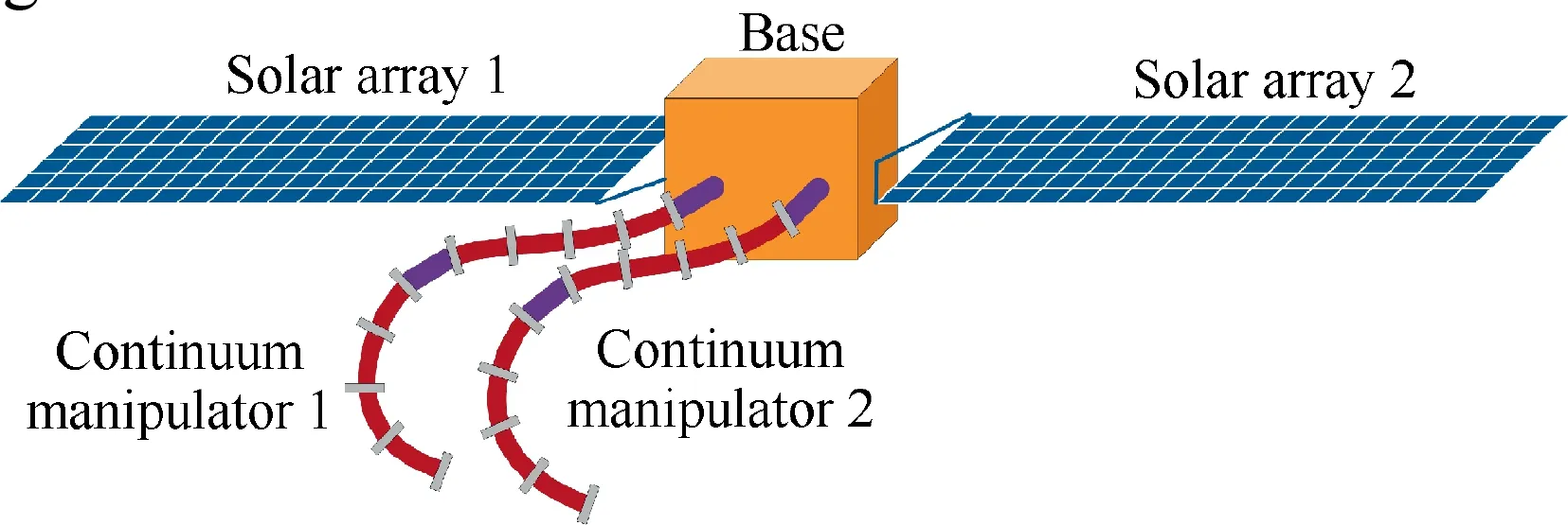
Fig. 1 A CMSR.

Fig. 2 Structure of a continuum manipulator.
Manipulators,which consist of links and joints,usually perform tasks through the end-effector.Due to limited degrees of freedom, it is hard for these manipulators to work in the confined space. The manipulators made of metal usually have poor dexterity. However, CMSRs can be used to perform space missions, which are difficult for rigid-manipulator space robots.Continuum manipulators have great dexterity and can avoid rigid-body collisions with the target. More importantly,they are safe for interaction with astronauts. Due to their inherent compliance, continuum manipulators can play a crucial role in unstructured environments. This characteristic allows them to inspect the equipment in a narrow gap. Additionally, they can perform compliant operations to capture the target with different shapes and sizes, as shown in Fig. 3.
3. Dynamic modeling
In this section,the dynamic model for CMSRs is derived based on the Lagrangian formulation. The solar arrays are fixed on the base spacecraft without relative rotations. Σand Σ, as shown in Fig. 4, denote the inertial and body-fixed reference frames, respectively. The origin of the body-fixed reference frame is the base centroid, and the axes of the body-fixed reference frame are consistent with the principal axes of the base spacecraft. The flexible backbones are divided into the Euler-Bernoulli beam elements, as shown in Fig. 5. Disks and connectors are fixed on the flexible backbones. Therefore, the linear and angular velocity of disks and connectors can be expressed by the generalized coordinates of the nodes.
3.1. Continuum manipulators
Due to their slender structure,the flexible backbones are modeled as the Euler-Bernoulli beams.For node i, the generalized coordinate qis defined as:

where ris the position vector of node i in the inertial reference frame Σ. a= [aaaa]is the unit quaternion of the cross section at node i. εis the normal strain of the backbone at node i.
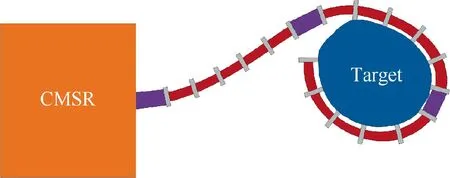
Fig. 3 A CMSR performing compliant operations.
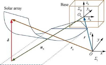
Fig. 4 Base spacecraft and solar arrays.
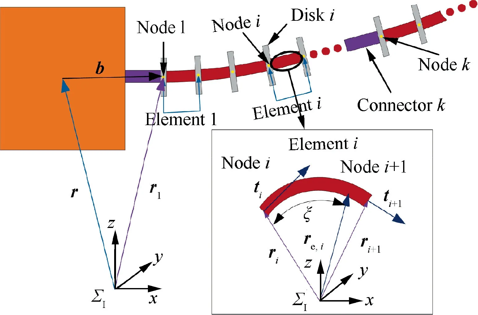
Fig. 5 Elements and nodes on the continuum manipulator.
The position vector rof the centerline of element i at ξ in the inertial reference frame Σ, as shown in Fig. 5, can be calculated by Hermite interpolation as follows:
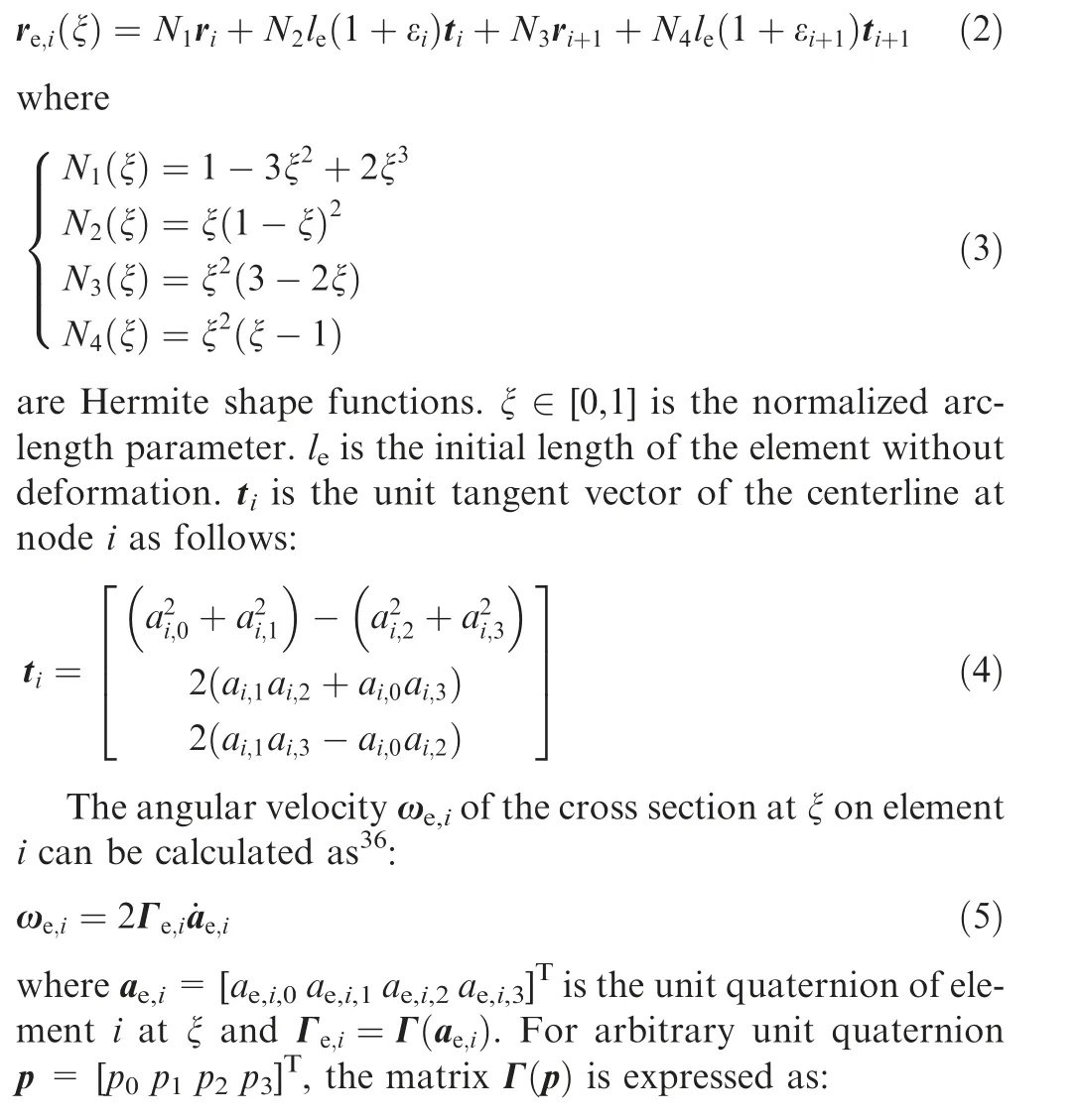
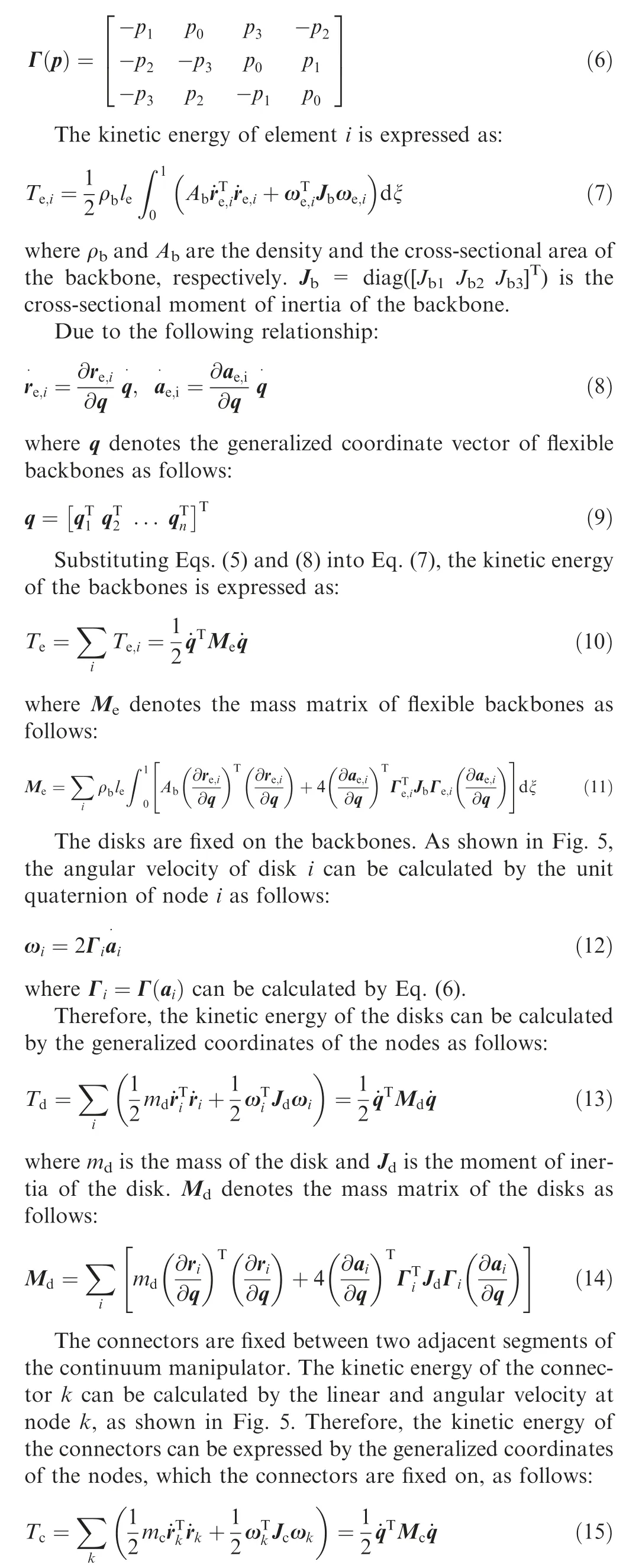
where mis the mass of the connector and Jis the moment of inertia of the connector. ω=2Γ˙ais the angular velocity of the connector. a= [aaaa]is the unit quaternion of the cross section at node k and Γ=Γ(a)can be calculated by Eq. (6). Mdenotes the mass matrix of the connectors as follows:
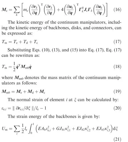
where E and G are Young’s modulus and the shear modulus of the backbone,respectively.κ,κ,and κare the curvatures of element i at ξ.
The orientation of node i is specified by the unit quaternion which is constructed to satisfy:

The quaternion representation is adopted to describe the orientation of the manipulator, which avoids the singularities caused by Euler angles. Generalized coordinates with respect to the inertial reference frame Σare used to describe the configuration of the continuum manipulators, resulting in the mass and stiffness matrices of adjacent modules being decoupled. Therefore, it is suitable for dynamic modeling of continuum manipulators with multiple modules.
3.2. Base spacecraft
To avoid the singularity of Euler angles,the quaternion representation of rotation is used to describe the orientation of the base spacecraft.A is the orthonormal rotation matrix between the inertial and body-fixed reference frames:

where a=(a,a)is the unit quaternion of the base spacecraft.ais the scalar and a= [aaa]is the vector part of the quaternion a. Iis an identity matrix. ‘‘~” denotes a skewsymmetric matrix of a vector. For arbitrary vector
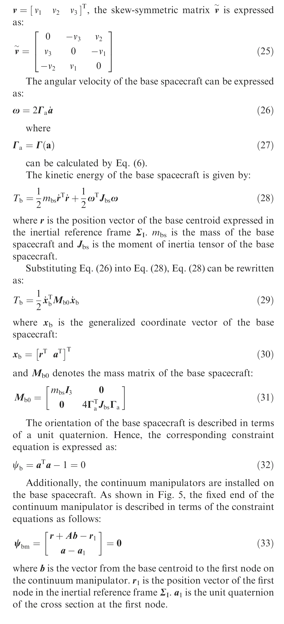
3.3. Solar arrays
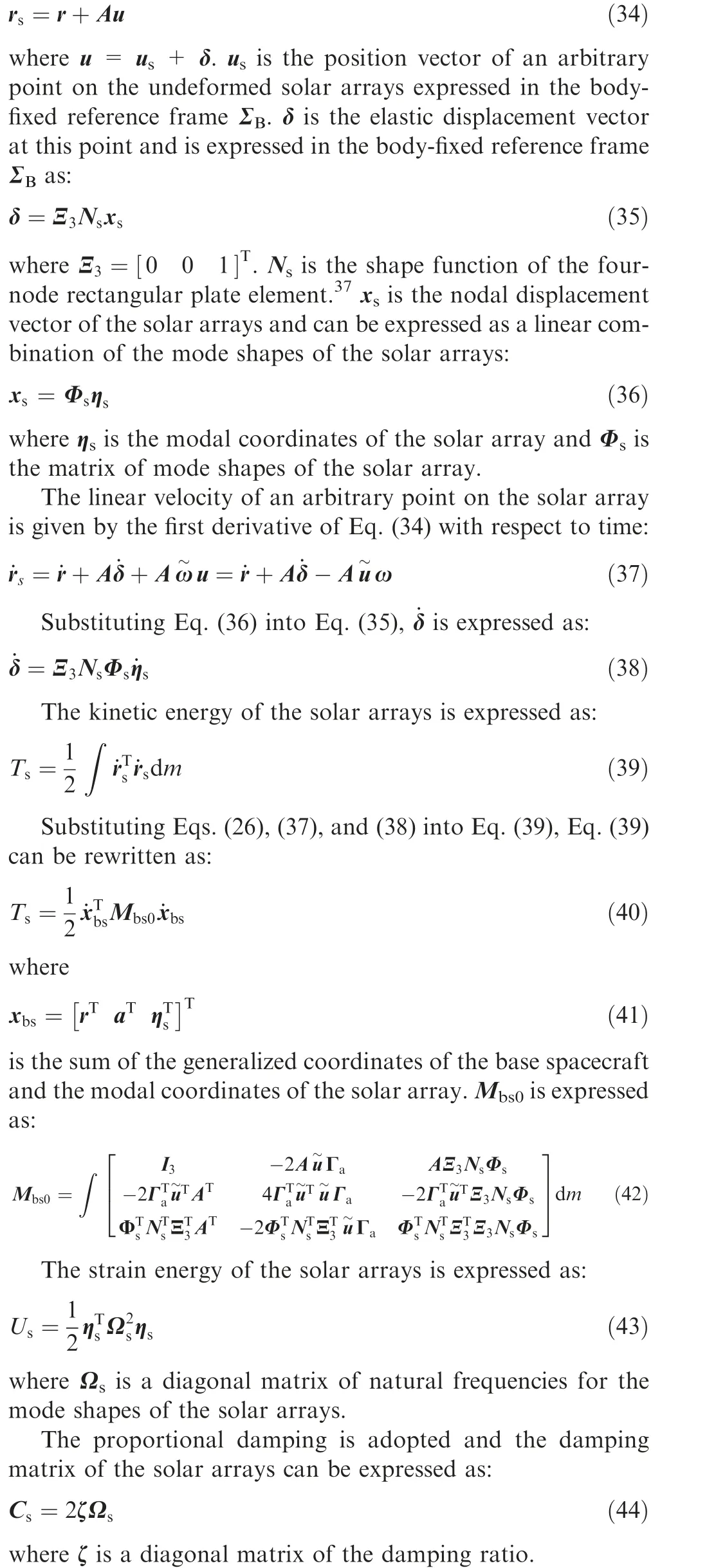
The elastic deformations of the solar arrays are described in terms of the mode shapes. To obtain the modal matrix, solar arrays are divided into four-node rectangular plate elements.Each node has three degrees of freedom:a transverse displacement and two rotation angles.
The position vector of an arbitrary point of the solar arrays,as shown in Fig.4,is expressed in the inertial reference frame Σas:
3.4. Actuation forces
The base spacecraft and the continuum manipulators are subject to the actuation forces. The generalized force of the actuation force applied on the base spacecraft is expressed as:

where fand τare the actuation force and torque vectors,which are applied on the base spacecraft and expressed in the body-fixed reference frame Σ, respectively. A and Γcan be obtained by Eqs. (24) and (27), respectively.
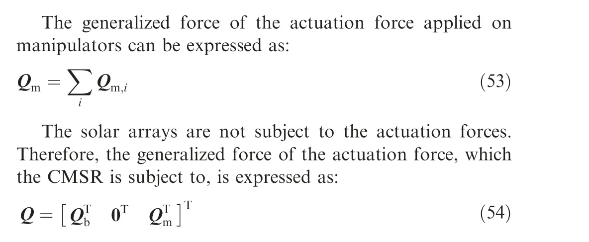
The continuum manipulators are driven by cables.The generalized force of the actuation force, which the manipulators are subject to, is derived by the principle of virtual work.
Fig.6 presents the actuation force applied on the disk i.As shown in Fig.6,the position vector of the routing hole on the disk i can be expressed in the inertial reference frame Σas:
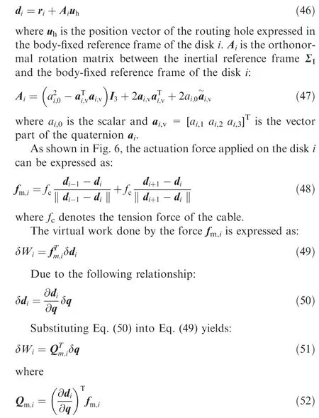
is the generalized force of the actuation force applied on disk i.
As shown in Fig. 6, the generalized force of the actuation force applied on the first disk of each segment can be obtained through making the first term on the right-hand side of Eq.(48) equal to zero. Similarly, the generalized force of the actuation force applied on the end disk of each segment can be obtained through making the second term on the right-hand side of Eq. (48) equal to zero.
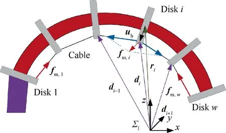
Fig. 6 Actuation force applied on the disk i.
3.5. Dynamic model
The total kinetic energy of a CMSR, including a base spacecraft, solar arrays, and continuum manipulators, is the sum of Eqs. (18), (29), and (40) as follows:
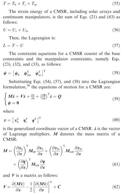
where C = [0 0 0;0 C0;0 0 0] is the damping matrix of a CMSR.
The proposed dynamic model for CMSRs is formulated as a set of differential–algebraic equations, which can be solved by Generalized α method.The equations of motion derived above can be used to calculate the dynamic responses of CMSRs, including the position and orientation of the base spacecraft, the elastic deformations of the solar arrays, and the configuration of the continuum manipulators. Based on the derived model, the dynamic characteristics of CMSRs can also be studied.
4. Analysis of the beating phenomenon
The novel CMSRs are composed of flexible components, such as solar arrays and continuum manipulators. To accomplish the scheduled tasks accurately and efficiently, the vibration characteristics of the CMSRs need to be studied. In addition,excessive vibration could cause severe damage to the solar arrays. Therefore, we focus on the vibration problem of the solar arrays on a CMSR. When performing space missions,any slight collision between the continuum manipulator and the target will perturb the CMSR from its equilibrium state.We analyze the resulting elastic vibration of the solar arrays by linearizing the equations of motion about the equilibrium conditions.
The generalized coordinates x can be rewritten in a partitioned form as:
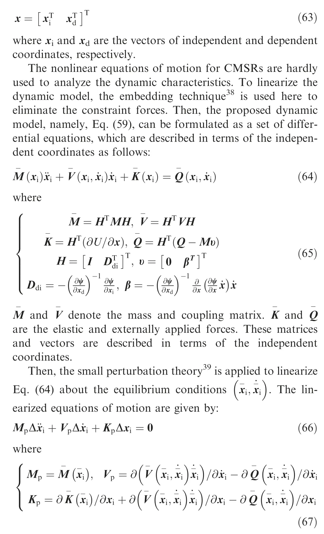
To simplify the expression,the symbol Δ is neglected in the following analysis. Eq. (66) is used to analyze the vibration of CMSRs and can be represented by block matrices in which the dependent coordinates are eliminated as follows:
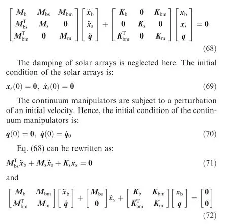
Because the elastic deformations of the solar arrays are relatively small in relation to their size, we first substitute Kx≈0 into Eq. (71). Then, we obtain:
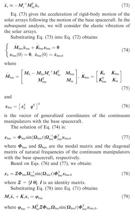
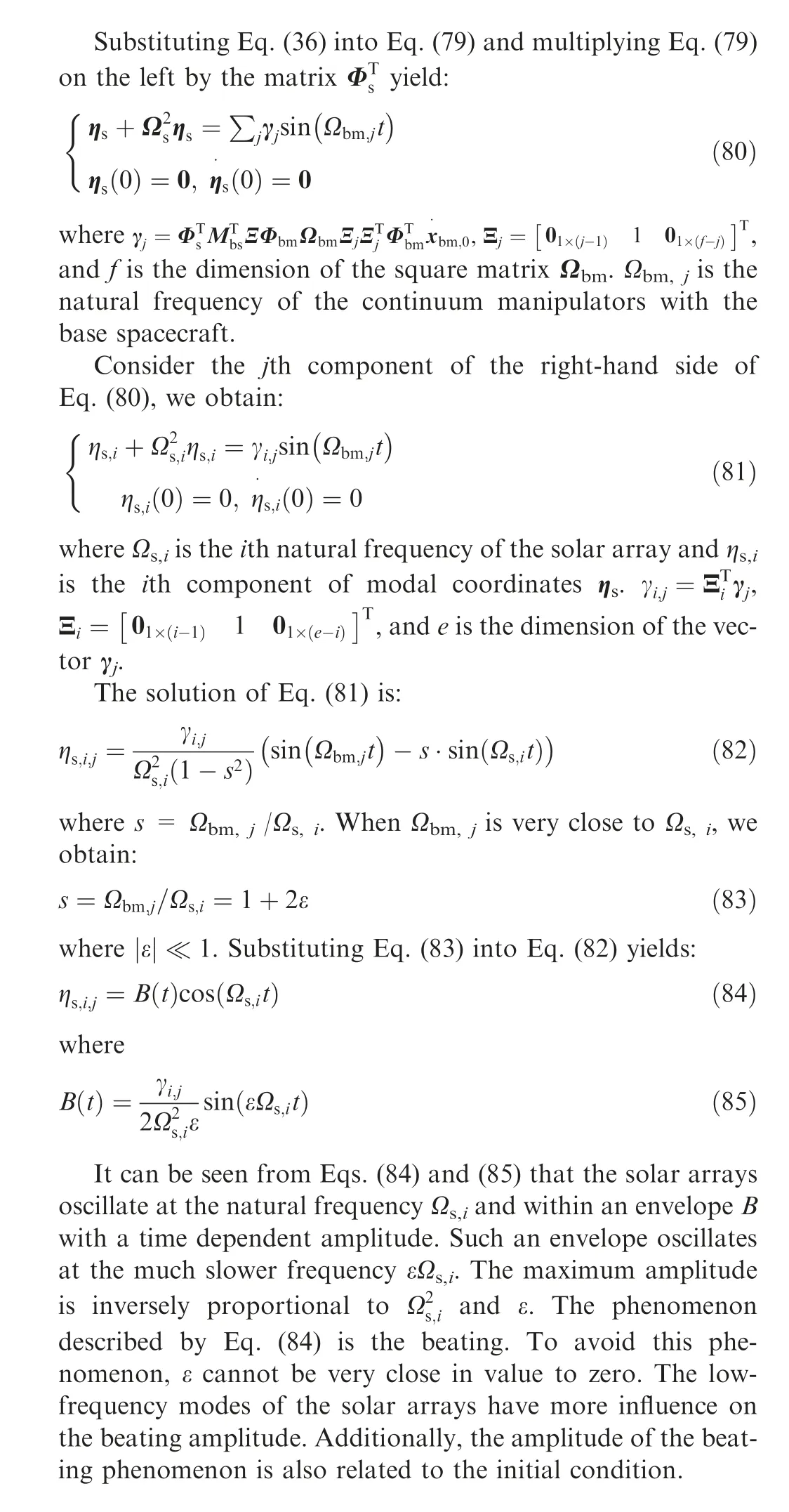
5. Numerical results and analysis
In this section,the dynamic response of a CMSR is calculated.Additionally,this section analyzes the influence of natural frequencies of continuum manipulators on the process of energy transfer.The simulation parameters of the base spacecraft and the solar arrays are presented in Tables 1 and 2.There are two continuum manipulators on the base spacecraft and each manipulator consists of two modules.The geometric and material parameters of each module are shown in Table 3.The time step length of Generalized α method is 0.005 s.
5.1. Dynamic responses
The coupling among the base spacecraft,continuum manipulators, and solar arrays, complicates the dynamic response of a CMSR. Based on the proposed dynamic model, the dynamic responses of a CMSR with two kinds of initial velocities are analyzed. In the first case, the initial velocities of two continuum manipulators are coincident, as shown in Fig. 7(a). In the second case,the initial velocities of two continuum manipulators are opposite, as shown in Fig. 7(b). In this simulation example, the Young’s modulus of the flexible backbones is 45 MPa.
Figs. 8 to 10 show the dynamic response of the CMSR,which is subject to an initial velocity shown in Fig. 7(a).Fig. 8 shows six instances of the dynamic response of the CMSR. The solar arrays vibrate with the movement of the base spacecraft. The rigid-body motion of the base spacecraft and the elastic deformations of flexible components appear simultaneously. Fig. 9 presents the displacement and the quaternion of the base spacecraft. Because the CMSR is subject to the initial velocity in the z direction, the z coordinate of the base centroid increases with time. The rotation of the base spacecraft includes fitful pauses,which are mainly caused by the oscillations of the continuum manipulators. Due to the angular momentum conservation, the base spacecraft undergoes continuous rotation. The quaternion representation is adopted to avoid the singularities caused by Euler angles, so it is suitable for large overall motion modeling of space robots.The coordinates of the end of two continuum manipulators are shown in Fig. 10. Due to the structure of the CMSR is symmetrical and the initial velocities of two continuum manipulators are coincident, the movement of two continuum manipulators are the same.
Figs. 11 to 13 show the dynamic response of the CMSR,which is subject to an initial velocity shown in Fig. 7(b). Six instances of the dynamic response of the CMSR are shown in Fig. 11. Under the action of the initial velocity, one manipulator moves up and the other manipulator moves down. The base spacecraft rotates around the x axis and the solar arrays vibrate. Fig. 12 shows the displacement and the quaternion of the base spacecraft. The CMSR is not subject to external loads. Due to the conservation of the linear momentum of the center of mass, the base spacecraft moves in the positive x direction when the center of mass of the continuum manipulators moves in the negative x direction, as shown in Fig. 12(a).Fig.12(b)presents the base spacecraft rotates around the x axis slowly, which is introduced by the initial velocity. Fig. 13 shows the coordinates of the end of two continuum manipula-tors. Two continuum manipulators move in the opposite direction.

Table 1 Base spacecraft parameters.

Table 2 Solar array parameters.
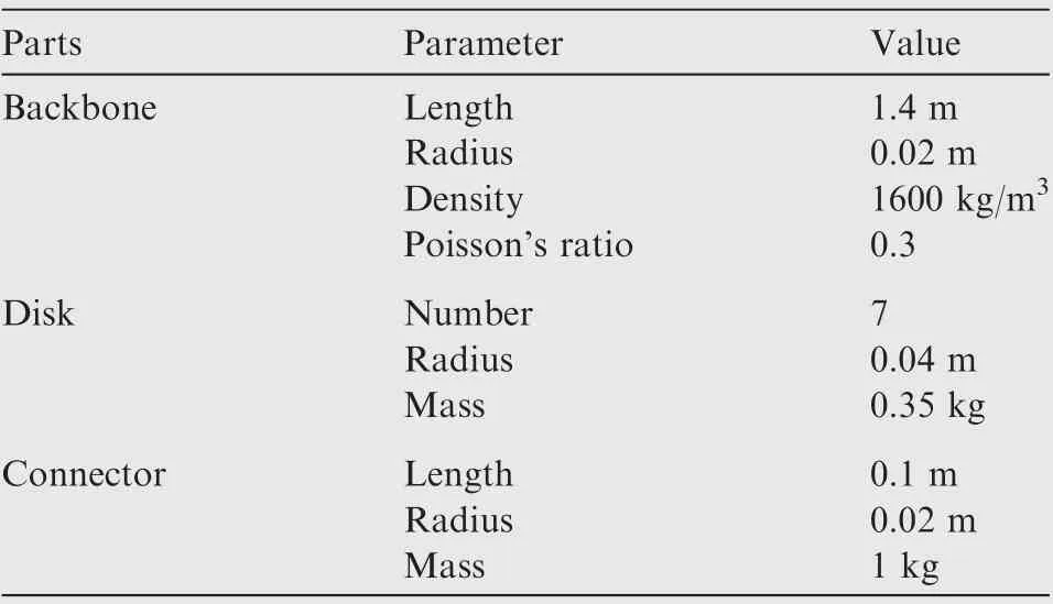
Table 3 Module parameters.
The proposed dynamic model can be used to calculate the position and orientation of the base spacecraft, the elastic deformations of the solar arrays, and the configuration of the continuum manipulators. The coupling between the rigid-body motion and the elastic vibration complicates the movement of the continuum manipulators.
5.2. Energy transfer
The large elastic vibration can cause serious damage to the solar arrays,which are important components for the CMSR.Therefore,this paper focuses on the vibration characteristics of the solar arrays. The CMSR consists of two kinds of flexible components, including the solar arrays and the continuum manipulators. These flexible components are installed on the base spacecraft. The process of energy transfer among these components is analyzed at different natural frequencies of the continuum manipulators. In this simulation example, the initial velocities of two continuum manipulators are shown in Fig. 7(a).
Fig. 14 shows the elastic vibration of the edge of the solar arrays on the CMSR.An obvious beating phenomenon occurs and the amplitude is 50.0 mm at the Young’s modulus of 45 MPa. However, when the Young’s modulus of the backbone is 120 MPa, the amplitude is only 8.8 mm. When the beating phenomenon occurs, the elastic vibration of solar arrays is relatively large. For the Young’s modulus of 45 MPa, the natural frequencies for the first two symmetric bending modes of the continuum manipulator are 0.10 Hz and 0.49 Hz, respectively. For the Young’s modulus of 120 MPa, the natural frequencies for the first two symmetric bending modes of the continuum manipulator are 0.17 Hz and 0.80 Hz, respectively. The Young’s modulus affects the natural frequencies. In essence, the amplitude of the solar arrays changes with the natural frequencies of the continuum manipulators.Therefore,the natural frequencies of the continuum manipulators have an important influence on the amplitude of the solar arrays.
Besides, the energy of each kind of component, including the base spacecraft,solar arrays,and continuum manipulators,is also calculated. Fig. 15 presents the energy transfer among them and the total energy of the CMSR. Due to the elastic vibration and low damping of the solar arrays,the total energy of the CMSR slightly decreases with time. Additionally, the energy is mainly transferred between the continuum manipulators and the base spacecraft.
Fig. 16 shows the percentage of the energy of the solar arrays accounting for the total energy. The energy transferred to the solar arrays increases significantly at the Young’s modulus of 45 MPa.Therefore,the natural frequencies of the continuum manipulators influence the energy transfer among the components.
5.3. Beating phenomenon
To indicate the influence of natural frequencies on the dynamic response of the CMSR, the elastic vibrations of the solar arrays are calculated for different natural frequencies of the continuum manipulators. The natural frequencies for the first two symmetric bending modes of the solar arrays are 0.49 Hz and 3.07 Hz. Table 4 presents the natural frequencies for the first two symmetric bending modes of the continuum manipulators with different Young’s moduli.Due to the inherent flexibility, the first natural frequency of the continuum manipulators is much less than that of the solar arrays. However, the second natural frequency of the continuum manipulators is very close to the first natural frequency of the solar arrays at the Young’s modulus near 50 MPa.
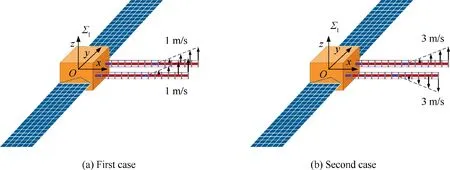
Fig. 7 Initial velocity of the CMSR.
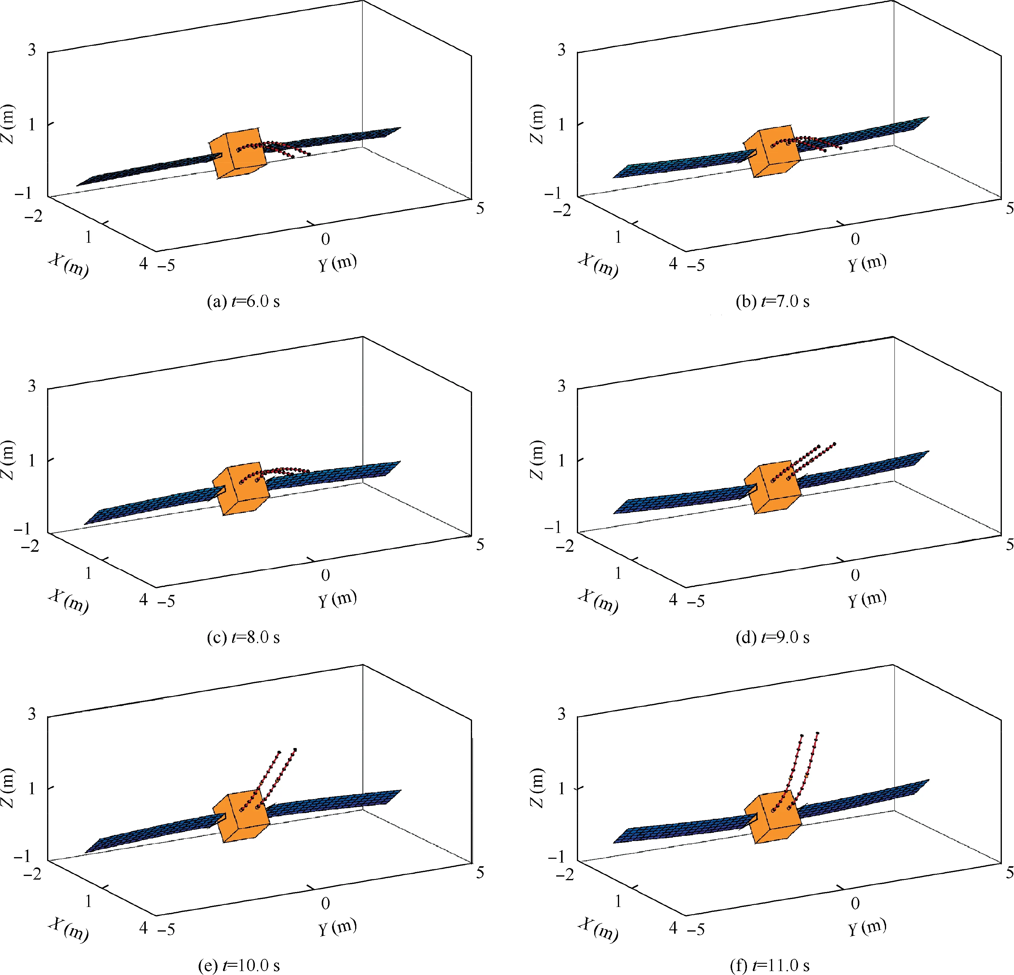
Fig. 8 Snapshots of a CMSR in the first case. (For better visibility, the deformations of the solar arrays are magnified 6 times.)
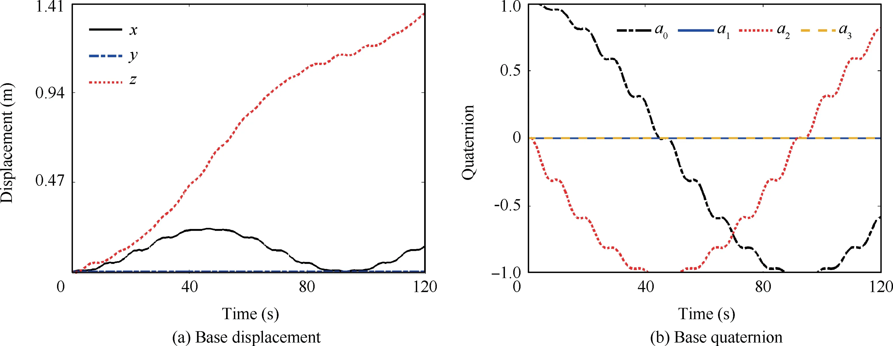
Fig. 9 Displacement and quaternion of the base spacecraft of the CMSR in the first case.
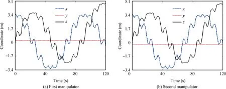
Fig. 10 Coordinates of the end of the continuum manipulators in the first case.
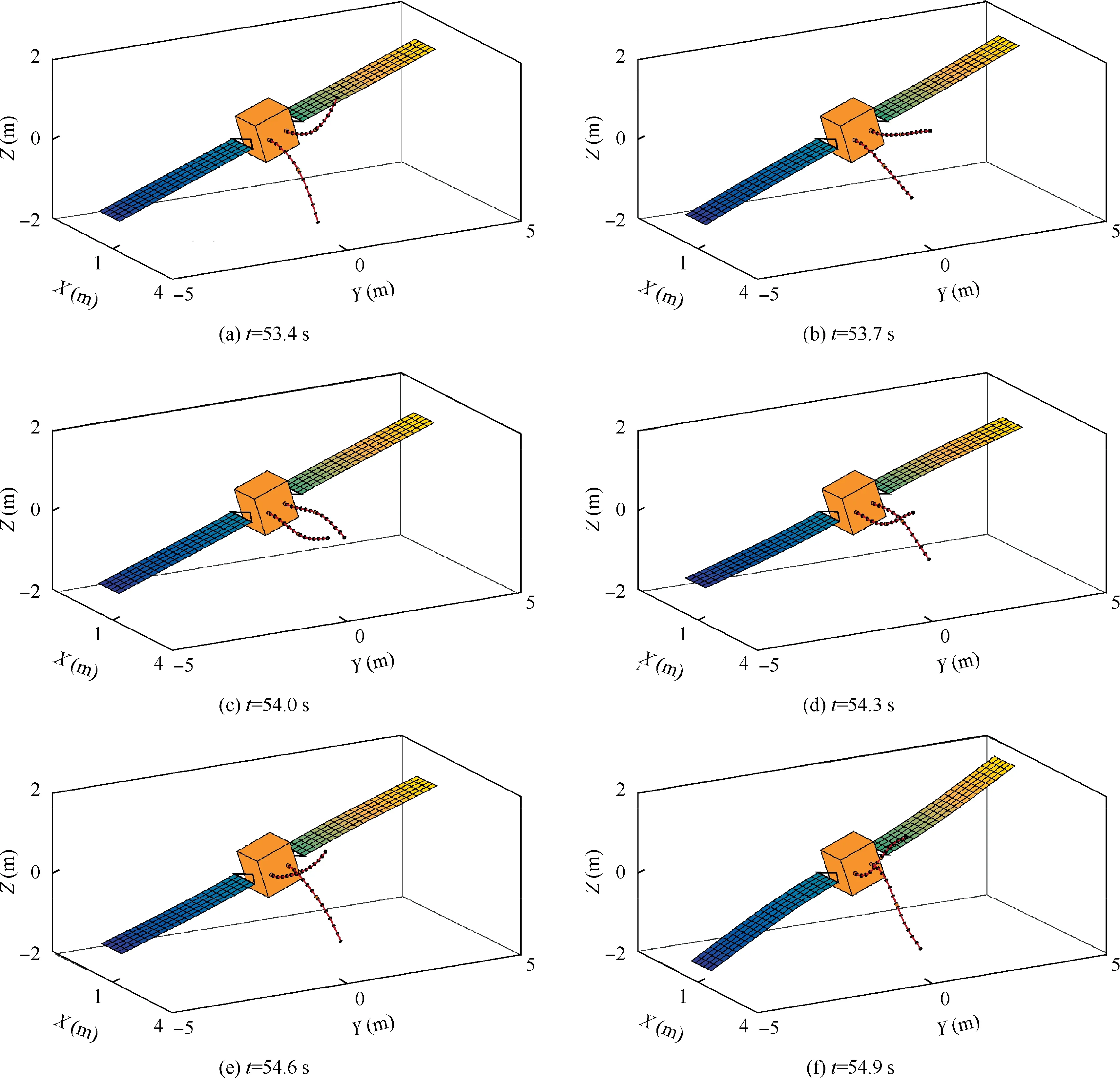
Fig. 11 Snapshots of a CMSR in the second case. (For better visibility, the deformations of the solar arrays are magnified 42 times.)
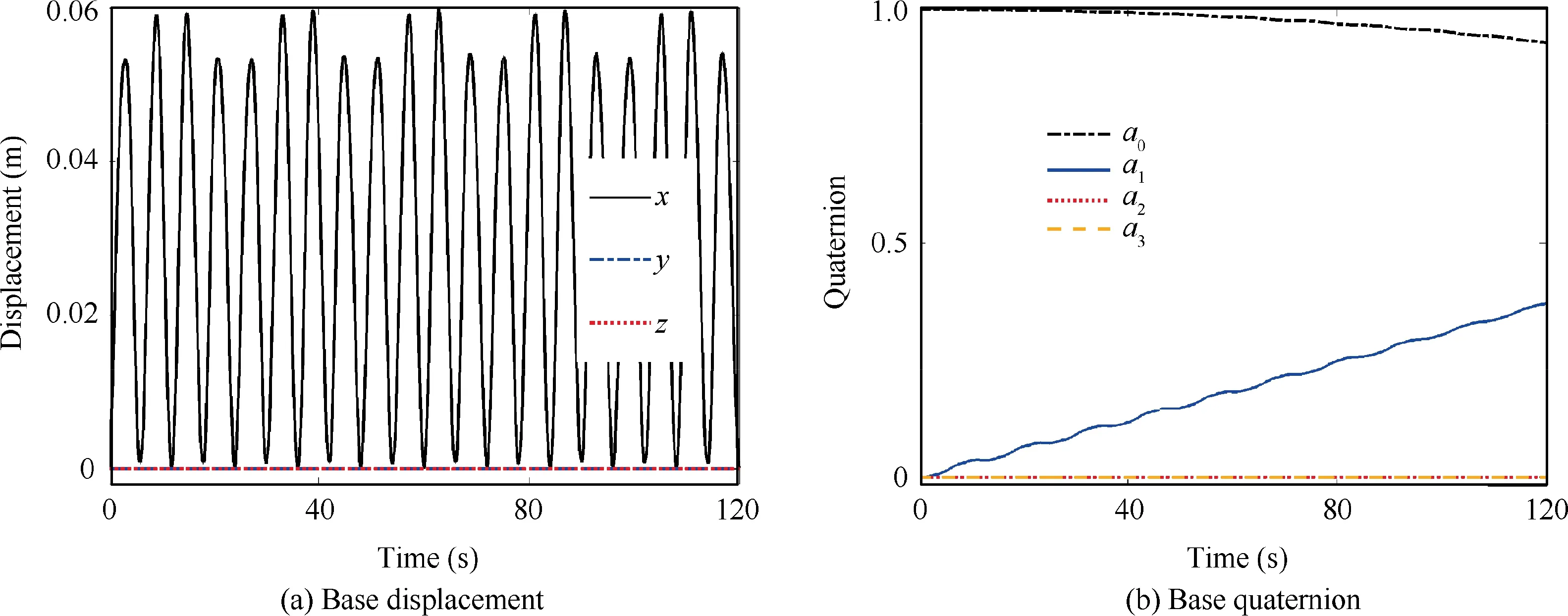
Fig. 12 Displacement and quaternion of the base spacecraft of the CMSR in the second case.
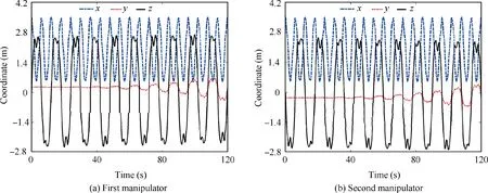
Fig. 13 Coordinates of the end of the continuum manipulators in the second case.
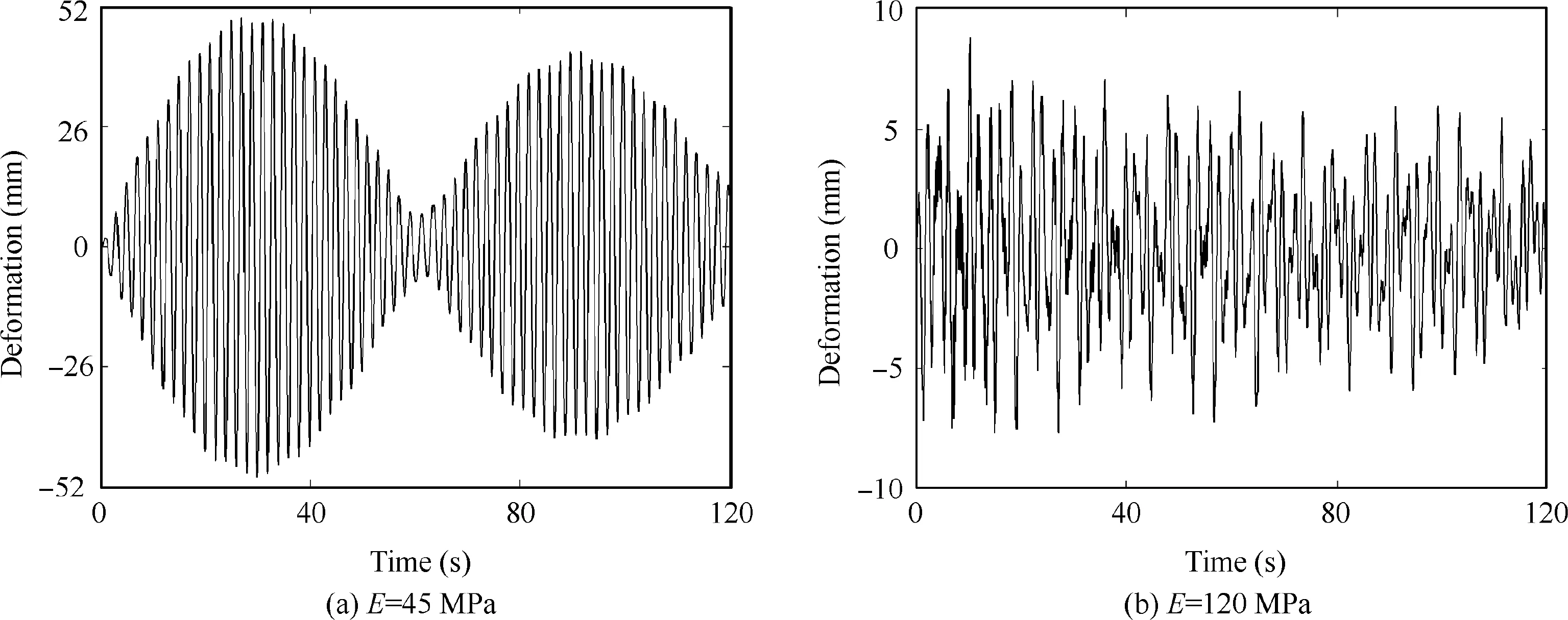
Fig. 14 Elastic vibration of the solar arrays on the CMSR.
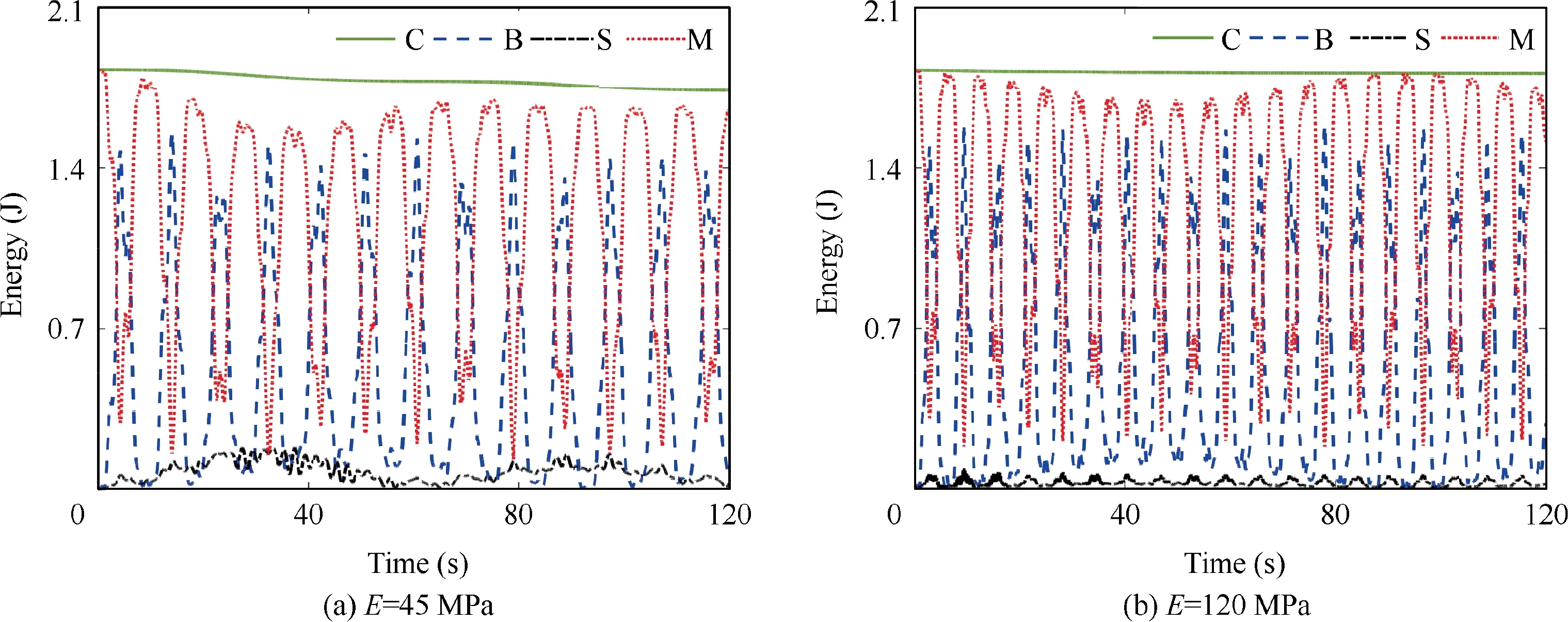
Fig. 15 Energy transfer among base spacecraft (B), solar arrays (S), and manipulators (M). C denotes the total energy of CMSR.
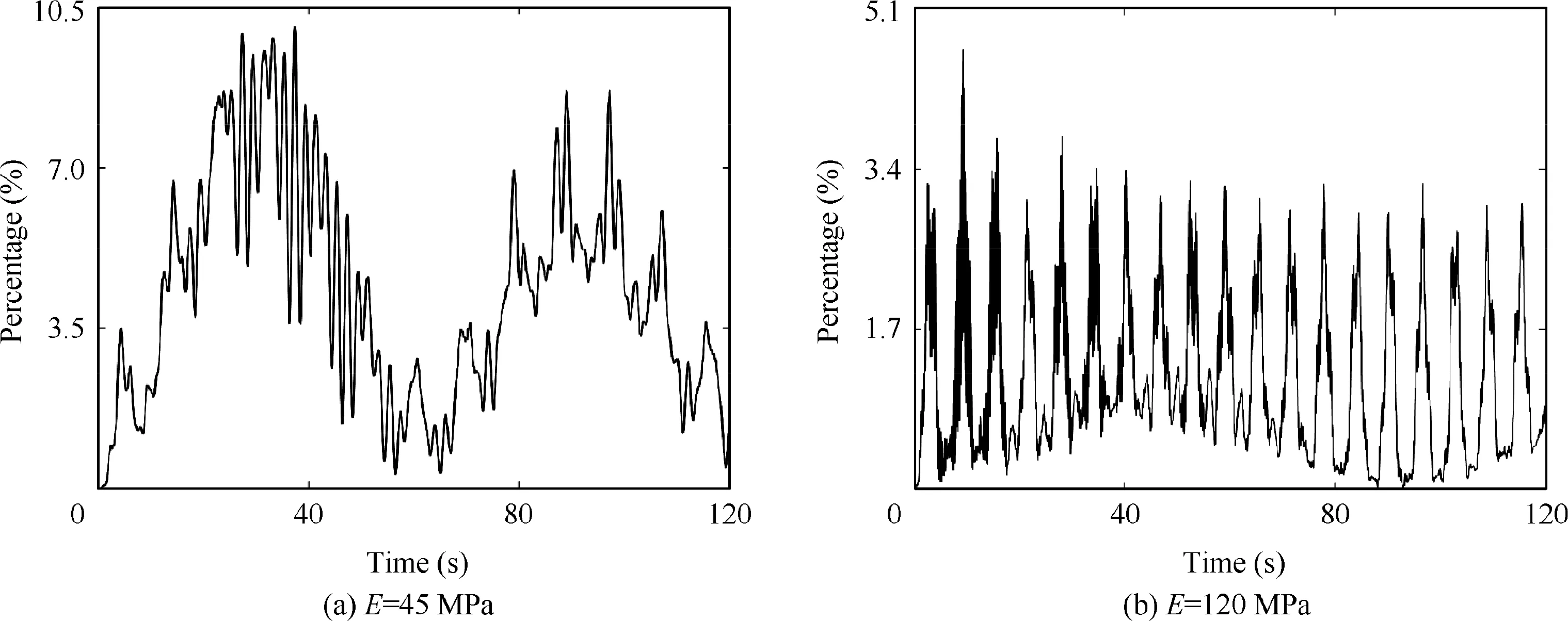
Fig. 16 Percentage of energy of solar arrays accounting for the total energy.

Table 4 Natural frequencies for the first two symmetric bending modes of the continuum manipulators with the different Young’s moduli.
Fig. 17 shows the elastic vibrations of the solar arrays at different natural frequencies ωfor the second symmetric bending modes of the continuum manipulators. An obvious beating phenomenon occurs when the natural frequencies of the continuum manipulators and the solar arrays are close.Fig. 18 shows that the amplitude of the solar arrays increases first and then decreases as the natural frequency of the continuum manipulators increases. The difference between the natural frequencies of the solar arrays and the continuum manipulators can be calculated. The amplitude and period of beating increase as this difference decreases. This trend coincides with Eq. (85).
To discuss the influence of the active actuation force on the vibration characteristics, the case where the manipulators are subject to the constant cable tension of 50 N is studied.At the initial time, the manipulators are in the equilibrium configuration under the action of the cable tension. The initial velocities of two continuum manipulators are the same as those in Fig. 7(a). The Young’s modulus of the flexible backbones is 45 MPa. Fig. 19 shows the elastic vibration of the edge of the solar arrays. An obvious beating phenomenon occurs.
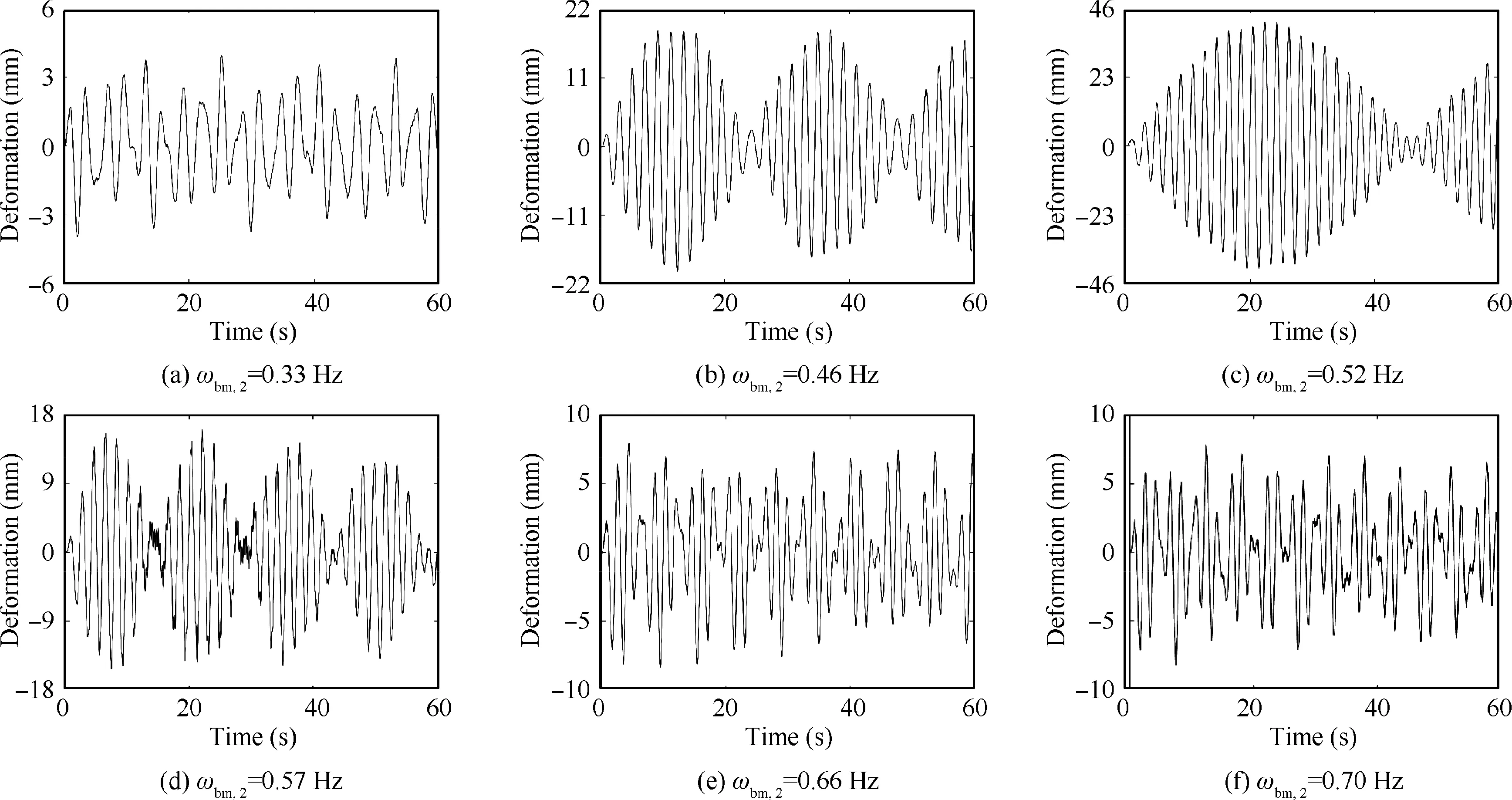
Fig. 17 Elastic vibrations of solar arrays for different natural frequencies of the continuum manipulators.
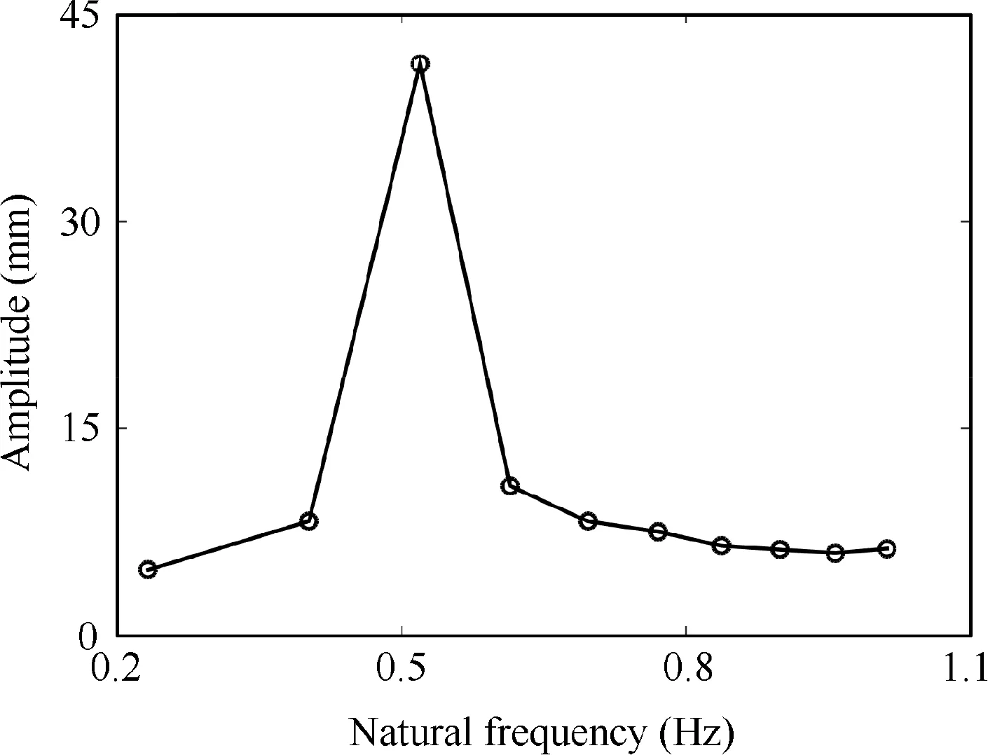
Fig. 18 Amplitude of solar arrays for different natural frequencies of the continuum manipulators.
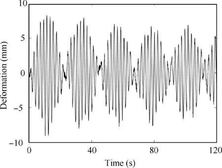
Fig. 19 Elastic vibration of the solar arrays under the action of the cable tension of 50 N.
The elastic vibration shown in Fig.19 is different from that shown in Fig. 14(a). The parameters used in these two examples are the same except for the actuation force.In the example shown in Fig. 14(a), the cable tension is zero. The natural frequencies for the first two symmetric bending modes of the continuum manipulator are 0.10 Hz and 0.49 Hz at the equilibrium configuration,respectively.However,in the example shown in Fig.19,the cable tension is 50 N.The natural frequencies for the first two symmetric bending modes of the continuum manipulator are 0.11 Hz and 0.47 Hz at the equilibrium configuration,respectively.Therefore,the actuation force will change the vibration characteristics of CMSRs. The reason for this phenomenon is as follows. The actuation force affects the equilibrium configuration. The generalized coordinates of the continuum manipulator are different for the equilibrium configurations with the different actuation force. The mass and stiffness matrices of the continuum manipulator are related to the generalized coordinates.Therefore,the actuation force has an influence on the natural frequencies.Because the equations of motion are linearized about the equilibrium conditions, the analysis of the beating phenomenon is effective for the cases with or without the actuation force.
The beating phenomenon may cause serious damage to the solar arrays.A method is provided to avoid this phenomenon,as shown in Fig. 20. First, the mass and stiffness matrices of the continuum manipulators and the solar arrays are calculated. Second, the natural frequencies of these flexible components are calculated.The natural frequencies of the continuum manipulators are calculated by considering the coupling effects among the continuum manipulators, the base spacecraft, and the solar arrays, as presented in Eq. (75). Third, Eq. (83) is applied to calculate the difference ε between the natural frequencies of the continuum manipulators and the solar arrays.Eq. (85) can be used to estimate the amplitude of the solar arrays. If this difference ε is relatively small,CMSRs may suffer from a beating phenomenon. Hence, the parameters need to be modified, such as the diameter and the bending stiffness of the continuum manipulators. The selected parameters will not cause the beating phenomenon until the frequency difference ε is relatively large.
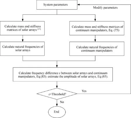
Fig. 20 A flow chart for determining whether the beating phenomenon will occur.
6. Conclusions
In this paper,a CMSR is proposed to perform space missions.The dynamic model of CMSRs is derived and the mechanism of the beating phenomenon is revealed. The main conclusions are as follows:
(1) The proposed dynamic model can be used to calculate the responses of CMSRs,including the position and orientation of the base spacecraft, the elastic deformations of the solar arrays, and the configuration of the continuum manipulators. The proposed method results in the mass and stiffness matrices of adjacent modules being decoupled, which is suitable for dynamic modeling of CMSRs with multiple modules.
(2) The natural frequencies of flexible components have an important influence on the elastic vibrations. A beating phenomenon occurs when the natural frequencies of the continuum manipulators are very close to those of the solar arrays.The amplitude and period of beating increase as the frequency difference decreases. The proposed method can avoid the beating phenomenon effectively.
The authors declare that they have no known competing financial interests or personal relationships that could have appeared to influence the work reported in this paper.
This work was supported by the National Natural Science Foundation of China (Nos. 91748203, 11922203, 11772074).
 Chinese Journal of Aeronautics2022年9期
- Chinese Journal of Aeronautics的其它文章
- Effect of vortex dynamics and instability characteristics on the induced drag of trailing vortices
- An effective crack position diagnosis method for the hollow shaft rotor system based on the convolutional neural network and deep metric learning
- A homogenization-planning-tracking method to solve cooperative autonomous motion control for heterogeneous carrier dispatch systems
- Static magnetic field analysis of hollow-cup motor model and bow-shaped permanent magnet design
- Adaptive modification of turbofan engine nonlinear model based on LSTM neural networks and hybrid optimization method
- A 3D CFD simulation of oil spray-collection and delivery process in an aeroengine inter-shaft bearing
