A novel adaptive lateral reentry guidance algorithm with complex distributed no-fly zones constraints
Yudong HU,Chngsheng GAO,*,Junlong LI,Wuxing JING,Wenxue CHEN
a School of Astronautics, Harbin Institute of Technology, Harbin 150001, China
b Beijing Institute of Electronic System Engineering, China Aerospace Science and Industry Corporation, Beijing 100854, China
KEYWORDS Guidance strategy;Heading corridor;Hypersonic vehicles;Improved artificial potential field;Lateral reentry guidance;Threat quantitative evaluation
Abstract Aimed at complex distributed no-fly zones avoidance problems, a novel adaptive lateral reentry guidance algorithm is proposed. Firstly, by introducing the improved attractive and repulsive potential fields, an improved artificial potential field method is developed. Combined with the proposed judgment criterion for whether a no-fly zone has been avoided, the proposed improved artificial potential field method effectively solves the reference heading angle determination problem under the constraints of complex distributed no-fly zones. Then, based on the proposed no-fly zone’s threat quantitative evaluation method and the reference heading angle determined by the proposed improved artificial potential field method, the heading corridor is improved to increase its sensitivity to the threat changes of the no-fly zones. Finally, for satisfying the requirements of complex distributed no-fly zones avoidance, a novel guidance logic via improved heading corridor is proposed to update the reference heading corridor adaptively in real time according to the threat and constraint changes of the no-fly zones, and the bank reversal logic is employed to control the lateral motion. The simulation results for nominal and dispersed cases indicate that the proposed guidance algorithm has high robustness, stability, and applicability, and is feasible and effective to deal with the complex distributed no-fly zones avoidance problems.
1. Introduction
Hypersonic glide vehicle has attracted attention of major aerospace countries and institutions worldwide due to its rapid speed,high precision,long-range lethality,and unique maneuverability.With the diversification and intelligence of reentry missions,hypersonic glide vehicle requires the ability to autonomously avoid threat areas and political restricted zones, as well as the ability to adapt to the flight mission changes.Therefore, the study on advanced guidance technology with high adaptability to complex flight environments has drawn everincreasing attention.
Currently, there are three categories of reentry guidance:off-line reference trajectory guidance,on-line reference trajectory guidance,and predictor–corrector guidance.The off-line reference trajectory guidance tracks the off-line planned trajectory,so it is difficult to meet the requirements of autonomy and has poor adaptability to flight mission and environment changes. On-line reference trajectory guidance generates an effective reference trajectory on line according to the vehicle’s current state and the flight environment, but its guidance accuracy is strongly constrained by the real time of on-line trajectory planning. The research on predictor–corrector guidance began in the 1980 s and its basic principle is that: First, the landing point is predicted. Then, the deviation between the predicted landing point and the target is compared in each guidance cycle. The control variables are corrected according to the deviation. The predictor–corrector guidance method does not rely on pre-designed or on-line planning trajectories,and has strong adaptability to uncertainty.Thus,the predictor–corrector guidance method has broad application prospects in improving the autonomy and intelligence of the hypersonic glide vehicles.
The greatest difficulty of the predictor–corrector guidaance is how to solve the multiple inequality constraint problems.To make it easier to solve, the predictor–corrector guidance is divided into longitudinal guidance and lateral guidance. The longitudinal predictor–corrector guidance has been deeply studied to solve the state, path, and control inequality constraint problems effectively.However, geographic constraints, especially the no-fly zone constraints, as complex inequality constraints, bring great challenges to lateral guidance.The core of the lateral predictor–corrector guidance is to update the heading corridor in real time according to the relative position of the vehicle, the no-fly zones, and the target.The avoidance problems of a single or more separated no-fly zones also have been deeply studied and well solved.With the diversification of reentry missions, the geographic constraints become increasingly complex. More and more attention has been paid to the avoidance problems of complex distributed no-fly zones.Liang and Rendeveloped a tentaclebased guidance method to provide a feasible reentry path under the complex no-fly zone constraints. To solve the forward path detection lack problem, Gao et al.proposed an improved tentacle-based bank angle transient lateral strategy for complex no-fly zone avoidance. However, due to the large amount of calculation and the reliance on empirical data,these tentacle-based guidance methods are not mature for complex distributed no-fly zones avoidance. Li et al.described the geographical relations between the target and no-fly zones by an improved artificial potential field to update the heading corridor and enforce multiple no-fly zone constraints. Yu et al.designed an analytical entry guidance method for numerous complex no-fly zones avoidance. Nevertheless, in these methods, only the nearest no-fly zone constraint is considered in each guidance cycle,the next no-fly zone cannot be considered until the current zone is passed. For considering multiple nofly zone constraints in each guidance cycle, Wang et al. developed a dynamic heading angle corridor under multiple no-fly zones.Yang et al.designed a guidance logic with consideration of two no-fly zones for multiple no-fly zones avoidance.Liang et al.presented the guidance logic via dynamic heading corridor and the guidance logic via waypoint vector.However,since the vehicle’s line-of-sight angle is taken as the reference heading angle, these guidance logics have poor adaptability to the more complex no-fly zone constraints. Besides, all of these guidance algorithms evaluate the no-fly zone’threat level only with consideration of the relative distance between the vehicle and no-fly zone boundary, which may lead to avoidance failure of certain no-fly zones when multiple no-fly zones are closely distributed. Because the threat level of the no-fly zone is reflected not only in the distance between the vehicle and the no-fly zone but also in the heading of the vehicle.Motivated by the above discussion, the guidance performance of these guidance methods cannot be guaranteed when multiple no-fly zones are closely distributed owing to their poor sensitivity to the threat and constraint changes of no-fly zones.Therefore, the reentry guidance for complex distributed nofly zones is investigated,and a novel lateral guidance algorithm with high sensitivity and adaptability is developed in this work.
The key to improving the guidance algorithm’s sensitivity and adaptability is to increase the reference heading corridor’s sensitivity to the threat and constraint changes of no-fly zones.First, the reference heading angle should be precisely determined under the constraints of complex distributed no-fly zones, for which it is necessary to accurately describe the relative position relationship among the no-fly zones, the target,and the vehicle.Due to its brief mathematical description,high efficiency, and strong adaptability, the artificial potential field method has been widely used in obstacle avoidance of robots,unmanned aerial vehicles,underwater vehicles,and cruise missiles.Consequently, the artificial potential field method is applied in this study to accurately determine the reference heading angle. However, when multiple no-fly zones and the target are closely distributed,potential fields are superimposed on each other, which makes the potential field very complicated, and may lead to the local minimum problem and the problem of minima deviating from the target. Thus, aimed at the reference heading angle determination problem under the constraints of complex distributed no-fly zones,by introducing the improved attractive and repulsive potential fields, a novel improved artificial potential field is proposed in this study.In addition, for simplifying the resultant artificial potential field as much as possible, a judgment criterion for whether a no-fly zone has been avoided is proposed and introduced in the improved artificial potential field.
Then, for improving the reference heading corridor’s sensitivity, accurately evaluating and ranking the threat degree of no-fly zones are essential preconditions. Evaluating the no-fly zone’s threat level only with consideration of the relative distance between the vehicle and the no-fly zone boundary, cannot meet the requirements of complex distributed no-fly zones avoidance. Therefore, in this paper, the factors that reflect the threat degree of no-fly zones are considered comprehensively and a novel no-fly zone’s threat quantitative evaluation method is proposed. Based on the proposed no-fly zone’s threat quantitative evaluation method and the reference heading angle determined by the proposed improved artificial potential field method, the heading corridor is improved to enhance its sensitivity to the threat changes of the no-fly zones.Moreover,as there is a scarce study on guidance logic for multiple no-fly zones and it is necessary to consider the no-fly zone constraints as much as possible in each guidance cycle for complex distributed no-fly zones avoidance,a novel guidance logic via improved heading corridor is proposed to adaptively update the reference heading corridor in real time according to the threat and constraint changes of the no-fly zones.
Motivated by the above discussion, the objective of this paper is to solve the complex distributed no-fly zones avoidance problem. The contributions of this paper can be summarized as follows: Aimed at complex distributed no-fly zones avoidance problems, a novel adaptive lateral reentry guidance algorithm is proposed in this paper. An improved artificial potential field is proposed to solve the reference heading angle determination problem under the constraints of complex distributed no-fly zones. For simplifying the resultant artificial potential field as much as possible, a judgment criterion for whether a no-fly zone has been avoided is proposed and introduced in the improved artificial potential field. Based on the proposed no-fly zone’s threat quantitative evaluation method and the reference heading angle determined by the proposed improved artificial potential field method,the heading corridor is improved to enhance its sensitivity to the threat changes of the no-fly zones. To meet the requirements of complex distributed no-fly zones avoidance, a novel guidance logic via improved heading corridor is proposed to adaptively update the reference heading corridor in real time. Moreover, the applicability, robustness, and stability of the proposed guidance algorithm are tested and validated by nominal and dispersed case simulations.
2. Reentry guidance problem formulation
After entering the atmosphere,hypersonic glide vehicles adjust the aerodynamic lift and drag by controlling the angle of attack and the bank angle to complete the precise attack or recovery missions. The advanced guidance technology is an important guarantee for ensuring flight safety and mission completion.
2.1. Reentry dynamics
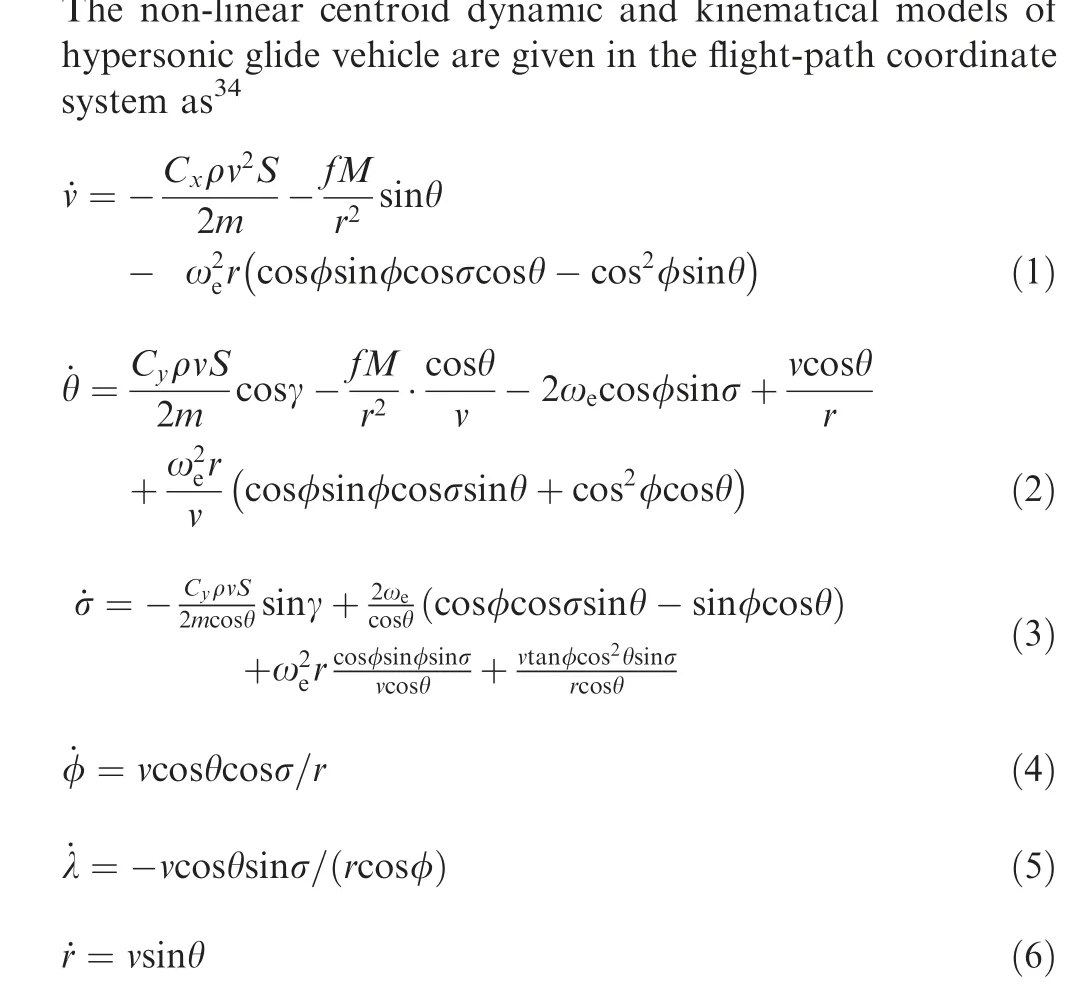
where v is the vehicle’s velocity,θ denotes the flight path angle,σ means the heading angle,r is the geocentric distance,φ and λ are the longitude and the latitude respectively, ɷdenotes the self-rotation angular rate of the Earth,γ means the bank angle,m is the mass of the vehicle,S is the vehicle’s reference area,ρ denotes the atmospheric density, and Cand Care the aerodynamic lift and drag coefficients, which are functions of attack α and Mach number.
2.2. Reentry constraints
Generally, reentry constraints include flight path constraints,no-fly zone constraints, terminal condition constraints, and control system constraints. There are three typical path constraints: the heating rate ˙Q, the dynamic pressure q and the aerodynamic load n

where αis the maximum angle of attack,αmeans the angle of attack corresponding to the maximum lift drag ratio,v, vare initial and terminal velocities respectively, and v, vare design parameters of the attack angle profile.
The bank angle and its angular rate constraints also need to be considered

3. Longitudinal reentry guidance
In general,the object of the reentry guidance is to steer the vehicle safely to the target with the prescribed conditions and satisfy all necessary constraints. In the predictor–corrector guidance algorithm,longitudinal guidance algorithm is employed to generate a feasible longitudinal trajectory and to satisfy all state,control,and path constraints.Although this study focuses primarily on the lateral guidance for complex distributed no-fly zones, the baseline predictor–corrector algorithmis utilized in longitudinal guidance for guidance integrality.
The core idea of the baseline predictor–corrector algorithm is to design a complete profile of the bank angle magnitude for generating a feasible longitudinal trajectory from the current condition to the target and satisfying the state, control, and path constraints. An energy-like variable e is introduced as the independent variable in the guidance algorithm, and the bank angle magnitude profile is given as a linear function of e
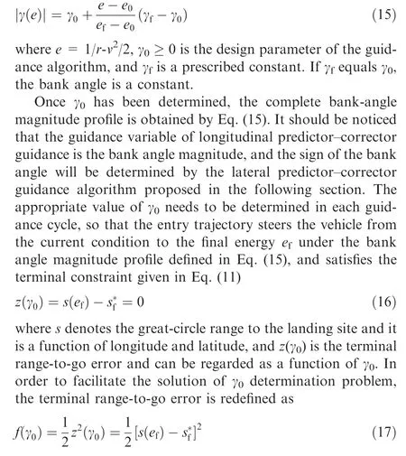
The key of longitudinal predictor–corrector guidance is to find the bank angle γthat minimizes the terminal range-togo error in Eq. (17). The detailed implementation process of the algorithm and the bank angle determination method are presented in Ref.
4.Lateral reentry guidance for complex distributed no-fly zones
For most of the reentry guidance algorithms, longitudinal guidance is used to determine the magnitude of the bank angle for a feasible longitudinal trajectory, as well as to satisfy all state, control, and path constraints. Lateral guidance is adopted to specify the sign of the bank angle to meet the geographic constraints and to steer the vehicle to the target.Although most of the reentry guidance algorithms have been proven effective for most guidance programs with no-fly zone constraints,when multiple no-fly zones are closely distributed,these methods may no longer be effective owing to their poor sensitivity and adaptability to the threat and constraint changes of no-fly zones.It should be noticed that the complexity of the no-fly zones’ distribution is reflected not only in the width of the flight path but also in the relative position of nofly zones.
In this section, based on the longitudinal predictor–corrector guidance, a novel adaptive lateral reentry guidance algorithm with high sensitivity and adaptability is proposed to deal with complex distributed no-fly zones avoidance problems. First, by introducing the improved attractive and repulsive potential fields, an improved artificial potential field method is developed. Combined with the proposed judgment criterion for whether a no-fly zone has been avoided, the proposed improved artificial potential field method effectively solves the reference heading angle determination problem under the constraints of complex distributed no-fly zones.Then, based on the proposed no-fly zone’s threat quantitative evaluation method and the reference heading angle determined by the proposed improved artificial potential field method,the heading corridor is improved to increase its sensitivity to the threat changes of the no-fly zones. Finally, for satisfying the requirements of complex distributed no-fly zones avoidance,a novel guidance logic via improved heading corridor is proposed to update the reference heading corridor adaptively in real time according to the threat and constraint changes of the no-fly zones in flight. The bank reversal logic is employed to control the lateral motion to avoid the no-fly zones and guide the vehicle to the target.
4.1. Heading corridor
In lateral predictor–corrector guidance, the bank reversal logic and the designed heading corridor are applied to specify the sign of the bank angle to avoid no-fly zones and steer the vehicle to the target. The core of the lateral predictor–corrector guidance is to design and update the reference heading corridor according to the relative position relationship among the vehicle, the no-fly zones, and the target. The conventional reference heading corridor takes the vehicle’s line-of-sight σ* as the reference heading angle and is shown in Fig. 1(a).
The corridor width is given as δσ,and the lower and upper boundaries of the heading corridor are expressed as
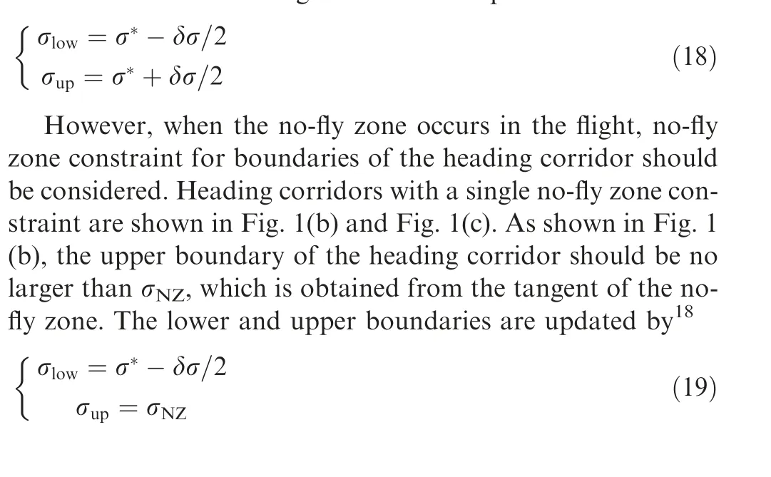

Fig. 1 Heading corridors and heading constraint for single no-fly zone.
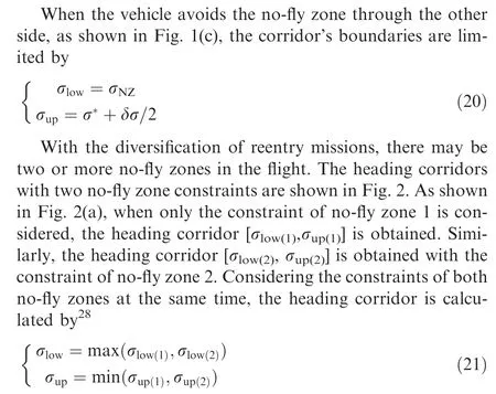
Therefore, it is possible to consider multiple no-fly zone constraints at the same time. If only a single no-fly zone constraint is considered in each guidance cycle, the guidance performance may not be guaranteed when there are multiple closely distributed no-fly zones in the flight, as shown in Fig. 3. Thus, it is necessary to consider the no-fly zone constraints as much as possible in each guidance cycle to realize the complex distributed no-fly zones avoidance. However, as shown in Fig. 2(b), limits for the two no-fly zones cannot be satisfied at the same time, only the heading limit for a single no-fly zone can be considered in a guidance cycle. Sometimes,it is impossible to take the heading limits for all the no-fly zones into account at the same time, especially there are complex distributed no-fly zones in the flight as shown in Fig. 3.Therefore, the heading corridor must be dynamically adjusted in real time according to the threat changes of the no-fly zones.A novel guidance logic is studied in this paper to consider the no-fly zone constraints as much as possible and give priority to the no-fly zones with high threat degrees.
Accurately evaluating and ranking the threat degree of nofly zones are essential preconditions for realizing the complex distributed no-fly zones avoidance. Currently, in most guidance algorithms,the no-fly zone’s threat level is evaluated only according to the relative distance between the vehicle and nofly zone boundary,which may lead to avoidance failure of certain no-fly zones when multiple no-fly zones are closely distributed. The reason is that the threat level of the no-fly zone is reflected not only in the distance between the vehicle and the no-fly zone but also in the heading of the vehicle. In this study, a novel no-fly zone’s threat quantitative evaluation method is proposed, based on which the heading corridor is improved and updated adaptively in real time according to the threat and constraint changes of the no-fly zones in flight to enhance the guidance algorithm’s sensitivity and adaptability.
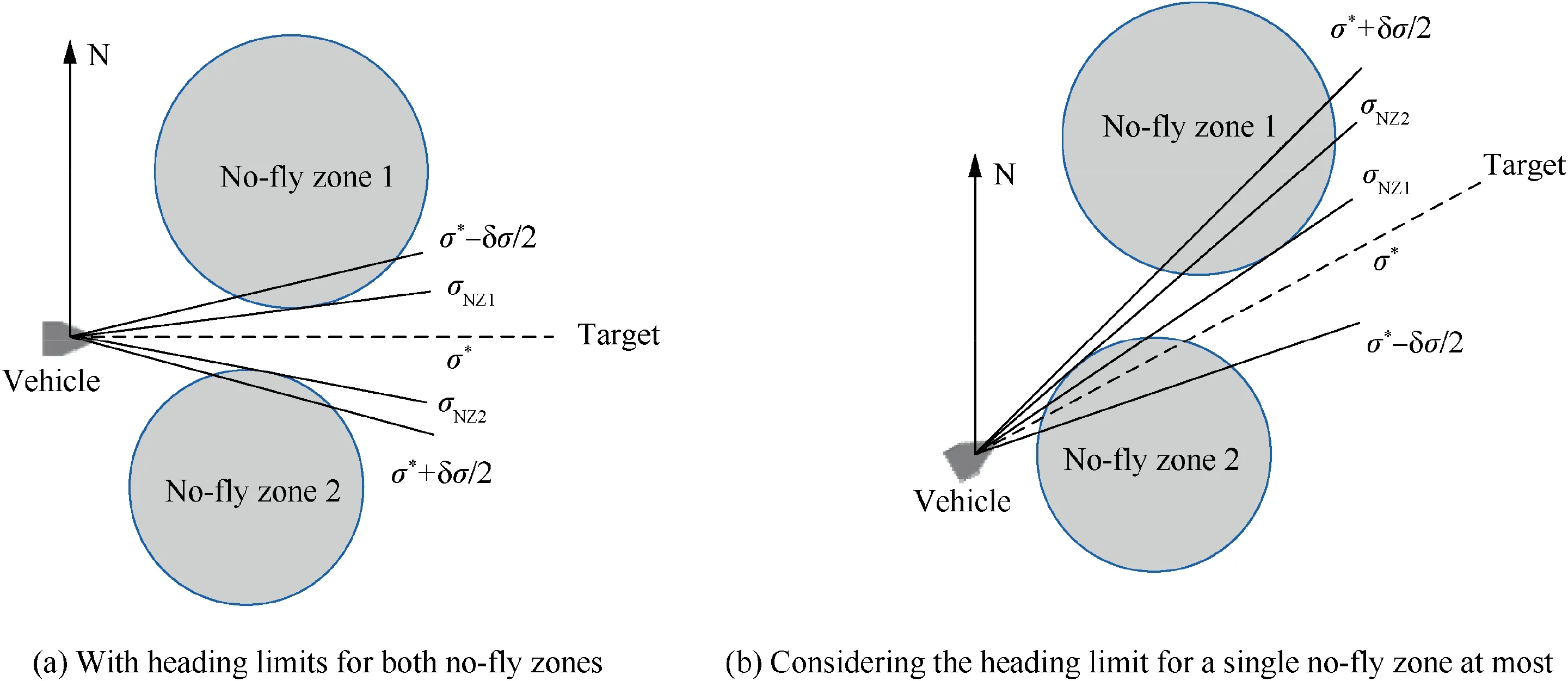
Fig. 2 Heading corridors for two no-fly zones.
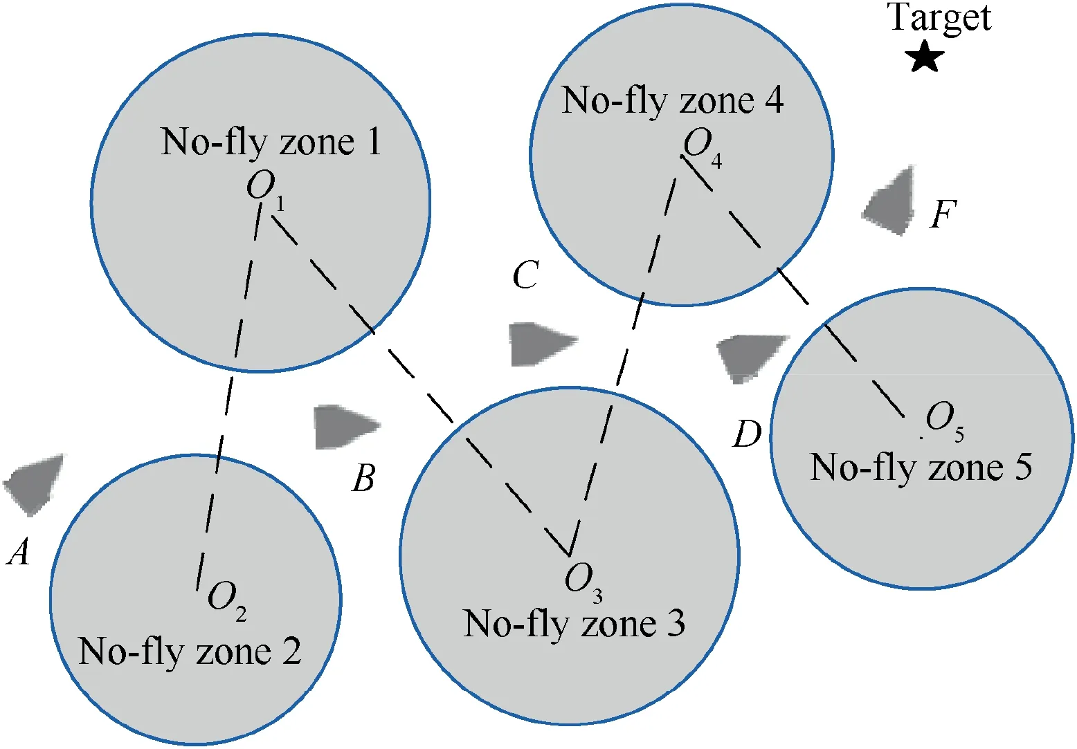
Fig. 3 Flight mission with complex distributed no-fly zones.
Besides, the vehicle’s line-of-sight is taken as the reference heading angle in most of the conventional reference heading corridor, which leads to its poor adaptability to complex distributed no-fly zones constraints. These methods are difficult to satisfy the requirements of avoiding complex distributed no-fly zones. Therefore, an improved artificial potential field method is studied in this paper to solve the reference heading angle determination problem under the constraints of complex distributed no-fly zones and to improve the guidance algorithm’s adaptability.
4.2. Reference heading angle determination based on improved artificial potential field
The key idea of the artificial potential field method is that: by setting the repulsive potential fields around obstacles and setting an attractive potential field around the target, the resultant force acts on the vehicle to avoid obstacles and to steer the vehicle safely to the target.Due to its brief mathematical description, high efficiency, and strong adaptability, the artificial potential field method has been widely used in obstacle avoidance of robots, unmanned aerial vehicles, underwater vehicles, and cruise missiles. In this study, the artificial potential field method is applied to determine the reference heading angle.However,when multiple no-fly zones and the target are closely distributed, the standard artificial potential field method is no longer applicable. Therefore, an improved artificial potential field method is studied in this section. First, a continuous differentiable logarithmic function is used to construct the potential field function with the latitude and longitude of the vehicle as the independent variable to accurately describe the relative positional relationship among the vehicle,the no-fly zones,and the target.Then,the attractive and repulsive potential fields are improved to reduce the superposition effect between potential fields and to avoid unnecessary maneuver. Finally, the potential field forces are expressed by the gradient of the latitude and longitude direction, and the relationship between geographic coordinate velocity and heading angle is studied to accurately determine the reference heading angle. In addition, a judgment criterion for whether a nofly zone has been avoided is also developed to remove the influence of the repulsive potential field of the no-fly zones, which have been avoided.
4.2.1. Improved attractive potential field
A continuous differentiable logarithmic function is taken as the potential field function with the vehicle’s current latitude and longitude as the independent variable. The improved attractive potential field is defined as
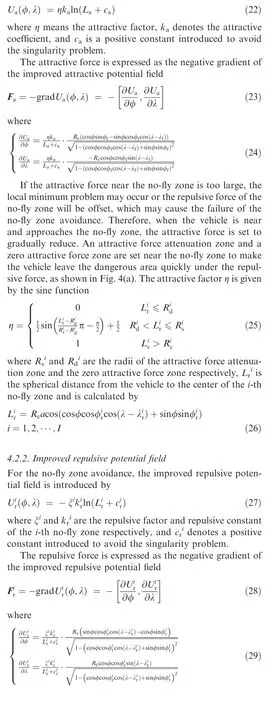
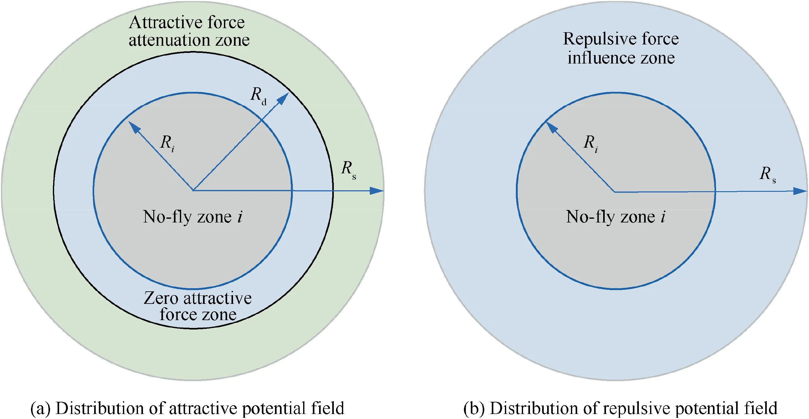
Fig. 4 Distribution of artificial potential fields around no-fly zone.
If the repulsive force is too small in the vicinity of a no-fly zone, the vehicle may enter this no-fly zone. If the repulsive force is too large, the vehicle may fail to avoid the near nofly zones when multiple no-fly zones are complex distributed.Therefore, the repulsive force is adjusted according to the distance from the vehicle to the no-fly zone and the influence radius of the repulsive force is limited.To reduce the complexity of the artificial potential field, the repulsive force influence radius is set the same as the radius of the attractive force attenuation zone. As shown in Fig. 4(b), when the vehicle approaches the no-fly zone, the repulsive force increases gradually. When the vehicle is far away from the no-fly zone, the repulsive force gradually decreases until the repulsive force is zero,and the repulsive factor ξis given by the cosine function

4.2.3. Judgment criterion for whether a no-fly zone has been avoided
If a no-fly zone has been avoided,the existence of its repulsive potential field may lead to a more complex resultant potential field, and even cause the failure of other no-fly zones avoidance, especially when multiple no-fly zones are closely distributed. Therefore, a judgment criterion for whether a no-fly zone has been avoided is proposed to remove the effect of the no-fly zones, which have been avoided. Besides, this judgment criterion is also introduced in guidance logic to improve the guidance algorithm’s adaptability to complex distributed no-fly zones avoidance.
The judgment criterion is put forward by considering the current heading of the vehicle and the relative position between the vehicle and no-fly zones comprehensively. As shown in Fig. 5, when the vehicle is located in the repulsive force influence zone, if the absolute value of the angle Δσbetween the vehicle’s heading and the azimuth angle of the vehicle relative to the center of the no-fly zone is no more than 90°,the vehicle is far away from the no-fly zone and has no danger of entering this no-fly zone. Namely, the no-fly zone has been avoided.The judgment criterion for whether a no-fly zone has been avoided is presented as
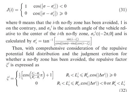
4.2.4. Reference heading angle determination
According to the definition of the gradient, the potential field force is located in the horizontal plane determined by the vehicle’s current location. Thus, the resultant force is also located in this horizontal plane and is calculated by
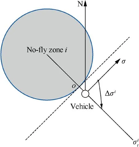
Fig. 5 Judgment criterion for whether a no-fly zone has been avoided.
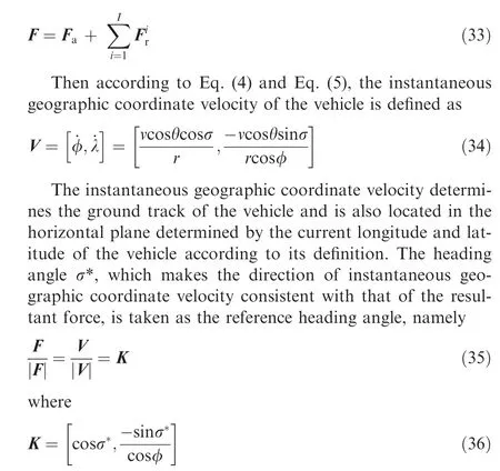
The reference heading angle σ*is accurately determined by Eqs.(34)-(36).So far,the reference heading angle determination problem under the constraints of complex distributed nofly zones has been solved. The proposed reference heading angle determination method is used to determine and update the reference heading corridor in this study.
4.3. Guidance logic for complex distributed no-fly zones avoidance
It is necessary to consider the no-fly zone constraints as much as possible and give priority to the no-fly zones with high threat degrees for complex distributed no-fly zones avoidance.In most guidance algorithms,only a single no-fly zone constraint is considered in each guidance cycle or the threat degrees of the no-fly zones are evaluated only relying on the relative distance.If there are multiple closely distributed no-fly zones, these guidance algorithms may be no longer effective owing to their poor sensitivity and adaptability to the threat and constraint changes of the no-fly zones in flight.Therefore, a guidance logic,which is highly sensitive to the threat change of the no-fly zones, is an important guarantee for realizing the multiple closely distributed no-fly zones avoidance. As accurately evaluating and sorting the threat degrees of no-fly zones are essential preconditions, a novel no-fly zone’s threat quantitative evaluation method is proposed in this section.Based on the proposed nofly zone’s threat quantitative evaluation method and the reference heading angle determined by the proposed improved artificial potential field method,the heading corridor is improved to enhance its sensitivity to the threat changes of the no-fly zones.Then,in order to meet the requirements of complex distributed no-fly zones avoidance, a novel guidance logic via improved dynamic heading corridor is proposed and is used to update the reference heading corridor adaptively in real time according to the threat and constraint changes of the no-fly zones in flight.
4.3.1. No-fly zone’s threat quantitative evaluation
Currently,most of the guidance algorithms for multiple no-fly zones avoidance consider that a closer no-fly zone is more threatening for the vehicle than a farther one. For dispersed no-fly zones avoidance problems,evaluating the threat degrees of the no-fly zones relying on relative distance is feasible.However, when complex distributed no-fly zones appear in the flight, evaluating the threat degree only relying on the relative distance may lead to incorrect evaluation of the no-fly zones’threats, and even cause the avoidance failure of certain nofly zones. This is because the threat degree of the no-fly zone is reflected not only in the distance from the vehicle to the no-fly zone but also in the heading of the vehicle.For instance,as shown in Fig.3,when the vehicle is in position B,although it is closer to no-fly zone 1 and 2 than to no-fly zone 3,its heading points to no-fly zone 3.The vehicle is far away from no-fly zones 1 and 2 and is approaching no-fly zone 3 at this time.Obviously, the threat degree of no-fly zone 3 is greater.
Therefore,in this section,a no-fly zone’s threat quantitative evaluation method is presented to quantitatively describe the threat of no-fly zones by comprehensively considering the vehicle’s current heading angle and the relative position between the vehicle and no-fly zones. If there are N no-fly zones that have not been avoided according to the proposed judgment criterion for whether a no-fly zone has been avoided,the threat degree of the n-th no-fly zone is defined as

where χ is the weight coefficient and is set as 0.5 in this paper.
It should be noted that the value of the no-fly zone’s threat degree has no practical physical meaning. The threat degrees are only used to rank the threat levels of the no-fly zones.From Eq. (37), it can be seen that the closer the no-fly zone to the vehicle or the closer the vehicle’s heading to the no-fly zone’s center, the greater the threat degree of this no-fly zone.By this evaluation method, the threats of no-fly zones can be quantitatively evaluated and sorted. The greater the threat degree of a no-fly zone, the more priority it should be given.
4.3.2. Guidance logic via improved heading corridor
A guidance logic with high sensibility to the threat changes of the no-fly zones is an important guarantee for the complex distributed no-fly zones avoidance. Currently, there is a scarce study on guidance logic for multiple no-fly zones avoidance.Meanwhile, it is necessary to consider the no-fly zone constraints as much as possible and give priority to the no-fly zones with high threat degrees in each guidance cycle for complex distributed no-fly zones avoidance. Therefore, based on the proposed no-fly zone’s threat quantitative evaluation method and the reference heading angle determined by the proposed improved artificial potential field method, the heading corridor is improved to enhance its sensitivity to the threat changes of the no-fly zones. Then, a novel guidance logic via improved heading corridor is studied to satisfy the requirements of complex distributed no-fly zones avoidance.
The main idea of the guidance logic via improved heading corridor is that: First, the judgment criterion for whether a no-fly zone has been avoided is used to find out the no-fly zones that have not been avoided.Then the threat quantitative evaluation method is employed to calculate the threat degrees of these no-fly zones and rank them according to their threat degrees.Finally,the reference heading corridor is updated considering the heading limits for the no-fly zones that have not been avoided and giving priority to the no-fly zones with high threat degrees. In fact, considering the three most threatening no-fly zone constraints in each guidance cycle is enough to meet the requirements of multiple closely distributed no-fly zones avoidance. For example, as shown in Fig. 3, when the vehicle is at location A, the threat degrees of no-fly zone 1 and 2 are much greater than those of no-fly zone 3, 4, and 5.When the vehicle is located at B, one or both of no-fly zone 1 and 2 must have been avoided, the threat degree of no-fly zone 5 is much smaller than that of no-fly zone 3 and 4, and at most three no-fly zones need to be considered. When the vehicle is at location C, one of the no-fly zone 1 and 3 must have met the judgment criterion for whether a no-fly zone has been avoided and at most three no-fly zone constraints need to be considered. Therefore, the reference heading corridor is updated considering at most 3 no-fly zone constraints.
If there are N no-fly zones that have not been avoided according to the judgment criterion for whether a no-fly zone has been avoided, the guidance logic via improved dynamic heading corridor can be summarized as follows:
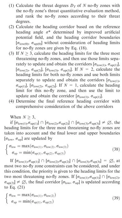
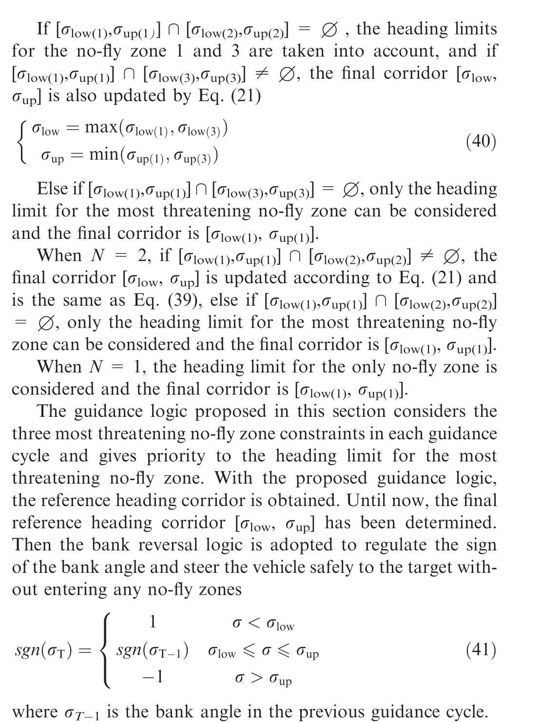
4.4. Lateral reentry guidance algorithm
Based on the developed improved artificial potential field algorithm and the proposed guidance logic via improved heading corridor mentioned above, the lateral reentry guidance problems of hypersonic glide vehicles with complex no-fly zones constraints are solved. The flowchart of the proposed lateral reentry guidance algorithm is shown in Fig.6,and the detailed steps are summarized as follows:
Step 1. Initialize the improved artificial potential field,mainly including the position of the target (λ, φ), the total number of no-fly zones I, the central position (λ, φ), the radius of each no-fly zone R,the repulsive factor ξ,the repulsive coefficient k,influence radius Rand zero attractive force zone radius Rof the i-th no-fly zone (for i = 1,2,∙∙∙,I), the attractive factor η, the attractive coefficient k, and positive constants cand c.
Step 2.Find out N no-fly zones that have not been avoided by the judgment criterion for whether a no-fly zone has been avoided. If N < 1, all of the no-fly zones have been avoided and skip to step 6, else go to step 3.
Step 3. Calculate the attractive force Fby Eqs. (23) - (26)according to the current position of the vehicle. Calculate the repulsive forces Fof the n-th no-fly zone (n = 1,2,∙∙∙,N) by Eq. (28), Eq. (29), and Eq. (32). Then the resultant force F can be obtained by Eq. (33) and the reference heading angle σ* is determined by Eq. (35) and Eq. (36).
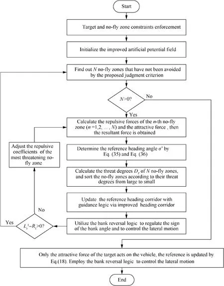
Fig. 6 Flowchart of the proposed lateral reentry guidance algorithm.
Step 4.Calculate the threat degrees Dof N no-fly zones by Eq. (37), and rank the no-fly zones according to their threat degrees.Employ the guidance logic via improved heading corridor to determine the final reference heading corridor [σ,σ].Then the bank reversal logic is utilized to regulate the sign of the bank angle to steer the vehicle to the target and avoid the no-fly zones.
Step 5.Determine whether the most threatening no-fly zone has failed to avoid, if L- R≤0, adjust the repulsive coefficients and go back to Step 3 until L-R>0,then return to Step 2 and re-execute the above steps.
Step 6. Calculate the attractive force Fby Eqs. (23) - (26)according to the current position of the vehicle, at this moment,only the attractive force of the target acts on the vehicle,and the resultant force F is calculated by F=F.The vehicle is guided to the target only by the attractive force.
It should be noted that although all of the no-fly zones have been avoided in a certain guidance cycle according to the judgment criterion for whether a no-fly zone has been avoided, this does not mean that the no-fly zone constraints no longer need to be considered in subsequent guidance.Because the no-fly zones may not satisfy the judgment criterion for whether a no-fly zone has been avoided once again in subsequent flight, especially when the no-fly zones and target are closely distributed, the judgment criterion for whether a no-fly zone has been avoided should be used throughout the flight.
5. Simulation analysis
5.1. Flight mission
In simulations, the proposed lateral reentry guidance algorithm is validated based on the CAV-H model developed in Ref.The mass of the vehicle is 907.2 kg, and the reference area is 0.4837 mThe maximal angle of attack and the angle of attack corresponding to the maximum lift drag ratio are 20° and 12°, respectively. v, vof the angle of attack profile in Eq. (13) are set as 5800 m/s and 3500 m/s. Initial location of the vehicle is λ= -30°,φ=0°.The location of the target is set as λ=21°,φ=1°.The initial and terminal velocity are set as v= 6500 m/s and v= 1500 m/s, respectively. The vehicle’s initial and terminal altitudes are h= 50 km and h= 25 km. The vehicle’s initial heading angle and the flight path angle are set as σ= -92°,θ=0.5°.Reentry path constraints are given as Q= 700 kW/m, n= 3 g, and q= 60 kPa. The bank angle and its angular rate are constrained by[-85°,85°]and 30(°)/s,respectively.The guidance cycle is 1 s. The tolerances of the vehicle’s terminal location,velocity, and altitude errors are set as 5 km, 100 m/s, and 3 km, respectively.
Considering that the complexity of the no-fly zones’ distribution is reflected not only in the width of the flight path, but also in the relative position of no-fly zones,flight mission constrained by five closely distributed no-fly zones is simulated to verify the performance of the proposed lateral reentry guidance algorithm. The flight paths between no-fly zones are narrow,for instance,the path width between no-fly zone 1 and 3 is only 220 km. Meanwhile, all no-fly zones are located near the line connecting the vehicle’s initial location and the target as shown in Fig.7.Locations and artificial potential field parameters of each no-fly zone are given in Table 1.
In the following, simulations for nominal cases are employed to verify the performance and applicability of the proposed lateral reentry guidance algorithm. The correctness and effectiveness of the proposed judgment criterion for whether a no-fly zone has been avoided and the developed no-fly zone’s threat quantitative evaluation method are also inspected in the nominal case simulations. The stability and robustness of the proposed lateral reentry guidance algorithm are tested by dispersed case simulations.
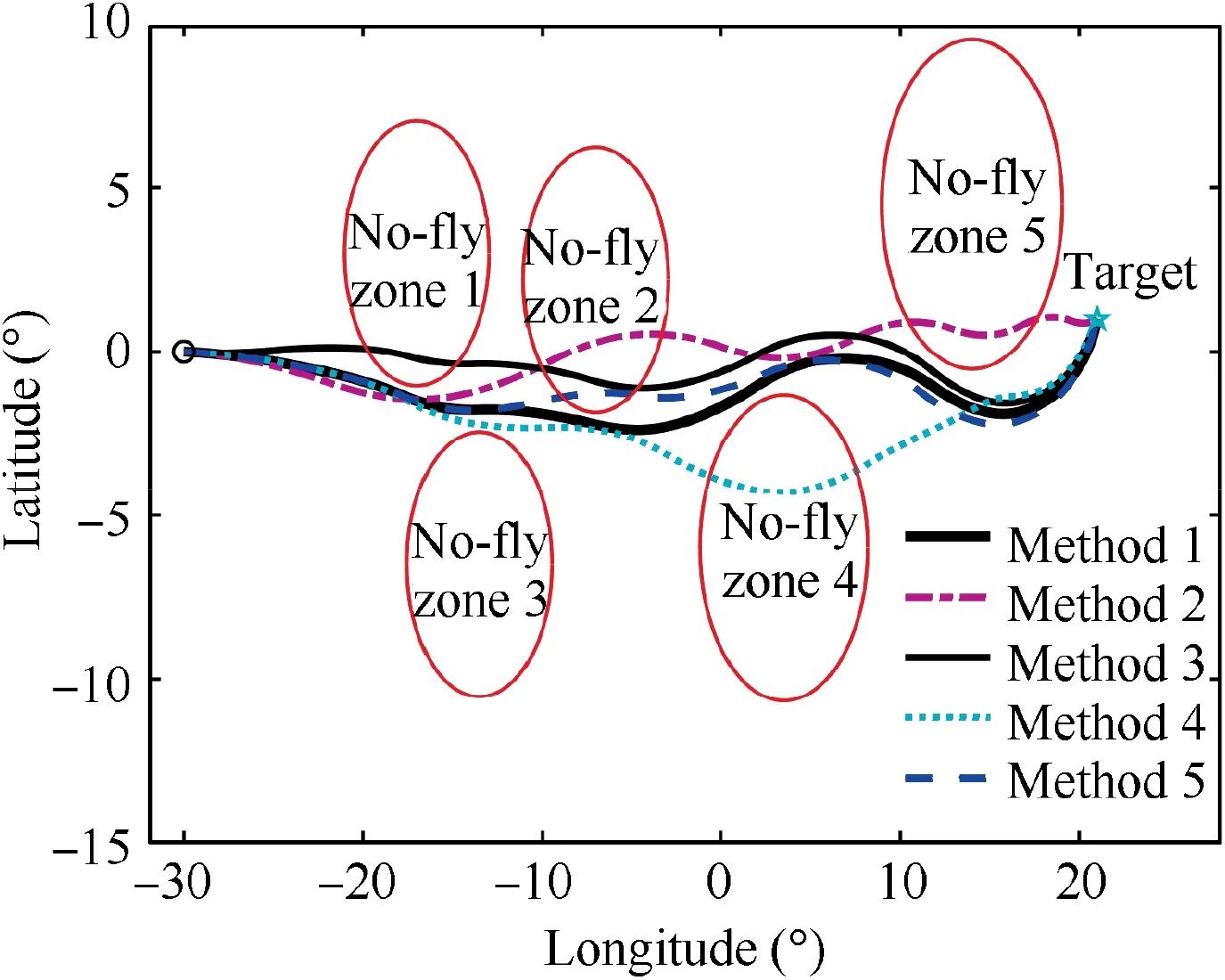
Fig. 7 Ground track of vehicle.
5.2. Nominal cases
In simulations, Method 1 is the proposed lateral guidance algorithm. For comparison, the dynamic heading corridor method,the standard artificial potential field method combined with the proposed guidance logic,and the improved artificial potential field based guidance algorithm developed in Ref.are adopted as Method 2,3 and 4 respectively to realize the lateral entry guidance. Besides, the proposed guidance algorithm without the function of the judgment criterion for whether a no-fly zone has been avoided near the no-fly zone 3 is employed as Method 5 to verify the validity of the proposed judgment criterion for whether a no-fly zone has been avoided.
The simulation results for nominal cases are shown in Figs. 7–14. Fig. 7 and Fig. 8 depict the vehicle’s trajectories in the lateral and longitudinal profiles respectively. From Fig.7 and Fig.8,it can be indicated that the terminal altitude constraints are guaranteed in the longitudinal profile. In the lateral profile,all of the methods successfully guide the vehicle to the terminal location. But only with Method 1, the vehicle can effectively avoid all of the no-fly zones. This is because the proposed guidance algorithm accurately and quantitatively describes the relative positional relationship among the vehicle,the no-fly zones, and the target to determine the reference heading angle,and has high sensitiveness to the threat changes of no-fly zones.
Fig. 9 shows the control-versus-time profiles, where the bank reversals are employed to avoid the no-fly zones and correct the terminal heading. Fig. 10 displays the heading angle profile, line of sight angle profile, and the reference heading angle profile of Method 1 and Method 2. It should be noted that in this study, the reference heading angle is set as σ*∊(-2π,0].From Fig.9 and Fig.10,it can be seen that when only the attractive force of the target acts on the vehicle, the reference heading angle of Method 1 and line of sight angle of Method 2 are very similar. When the vehicle enters the repulsion influence zones of certain no-fly zones, the deviation between the reference heading angle of Method 1 and line of sight angle of Method 2 is major due to the repulsive forces of no-fly zones. Besides, from Fig. 9 and Fig. 10, it also can be indicated that the reason for the failure to avoid the nofly zone 2 and 5 with Method 2 is that the DHC method has poor sensitivity to the threat changes of no-fly zones when the flight path is too narrow or the no-fly zones distribution is too complex. The specific cause of the failure to avoid the no-fly zone 2 with Method 2 is that the DHC method incorrectly assessed threat degrees of no-fly zone 2 and 3. Whenthe vehicle is closer to no-fly zone 3 and its heading points to no-fly zone 2, the threat degree of no-fly zone 2 is larger than that of no-fly zone 3, but the DHC method incorrectly gives the priority to the no-fly zone 3.And the failure of no-fly zone 5 avoidance with the DHC method is mainly due to the reference heading angle’s poor adaptability. With Method 3, the vehicle fails to avoid no-fly zone 1 and 2,mainly due to the reference heading angle determination error caused by superposing of multiple closely distributed repulsive potential fields and attractive potential fields.

Table 1 Locations and artificial potential field parameters of no-fly zones.
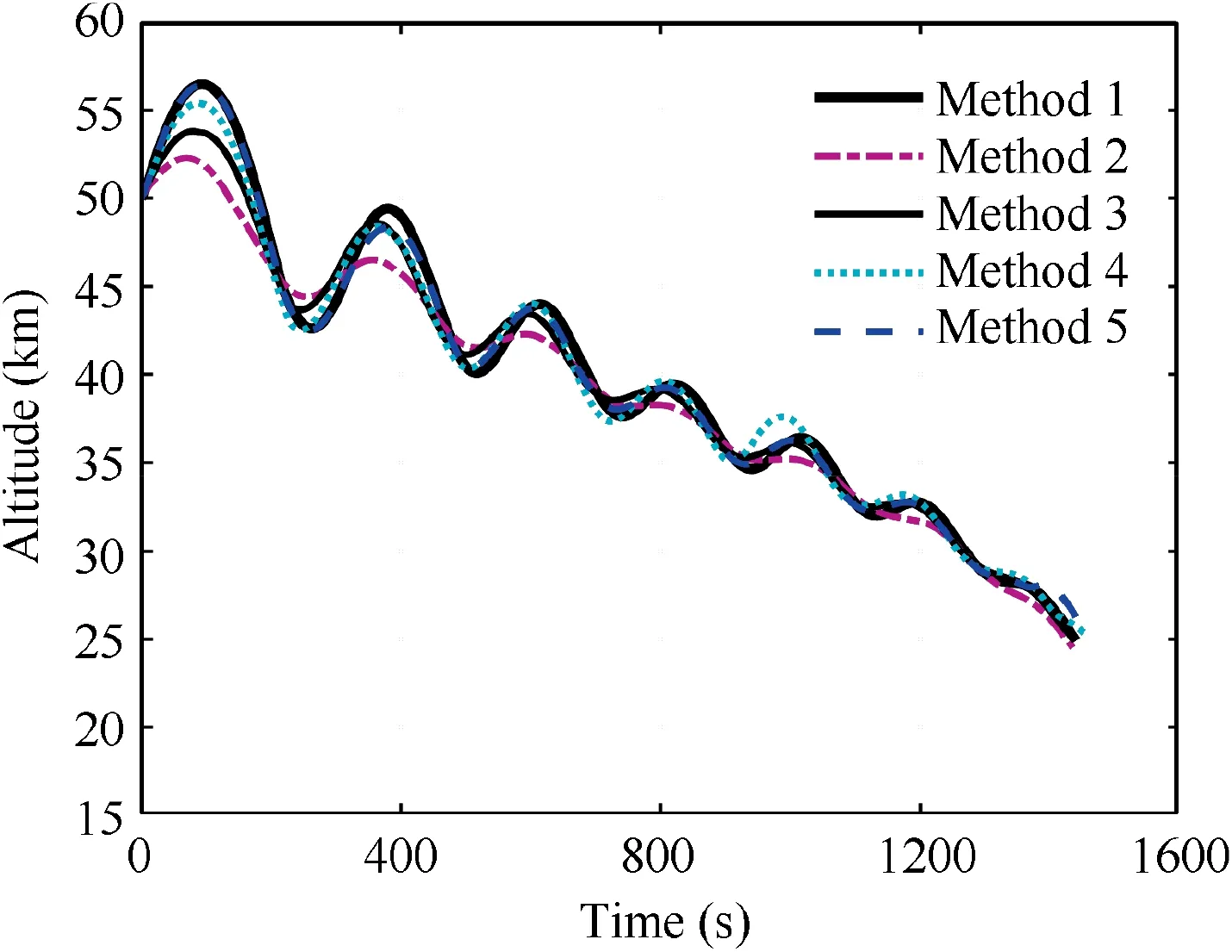
Fig. 8 Trajectories in longitudinal profile.
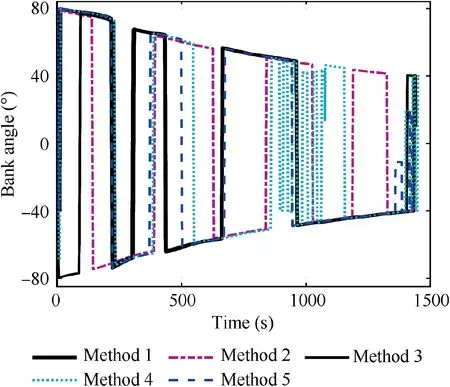
Fig. 9 Bank angle profiles for nominal case.
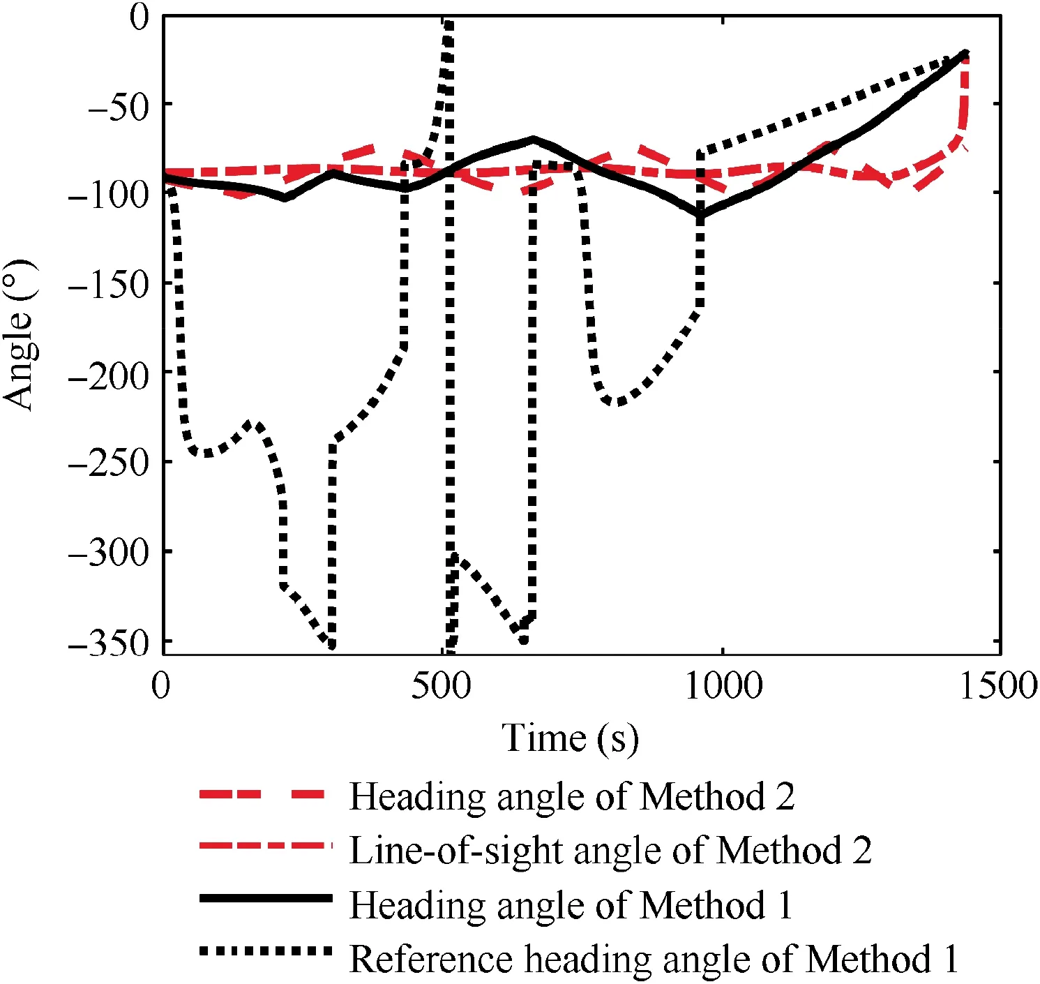
Fig. 10 Heading angle profile, line-of-sight angle profile, and reference heading angle profile with Methods 1 and 2.
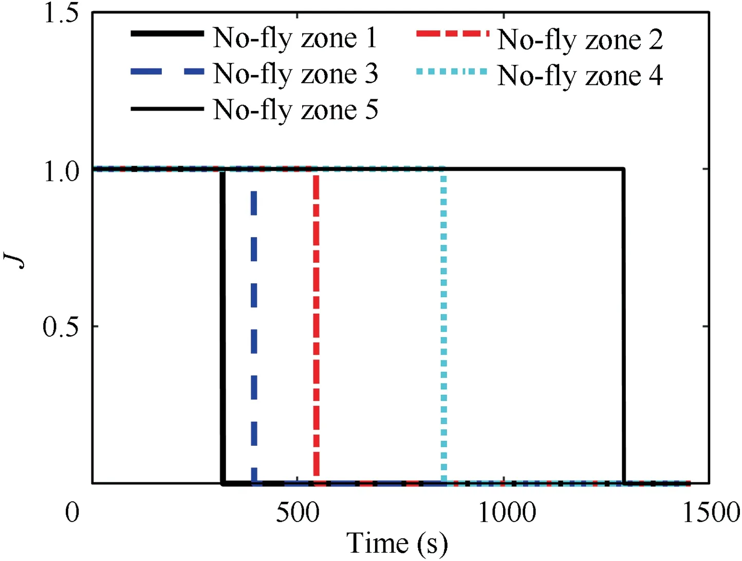
Fig.11 No-fly zone avoidance judgment results by the judgment criterion in Method 4.
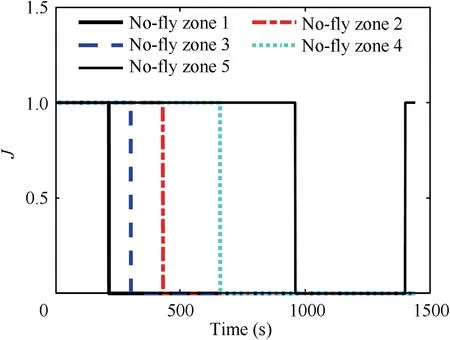
Fig.12 No-fly zone avoidance judgment results by the proposed judgment criterion.
From Fig. 7, it also can be seen that with Method 4, the vehicle does not avoid no-fly zone 4. Evaluating the no-fly zone’ threat level only with consideration of the relative distance and in each guidance cycle,and only considering the limits for a single no-fly zone are main reasons for the failure of no-fly zone 4 avoidance. Besides, the poor sensibility of the judgment criterion for whether a no-fly zone has been avoided is also the reason for the failure of no-fly zone 4 avoidance.Method 4 takes whether the vehicle has passed the tangent point between the vehicle and the no-fly zone as the judgment criterion, and the no-fly zone avoidance judgment results with Method 4 are shown in Fig. 11, where 1 means that the judgment criterion is not satisfied and 0 indicates that it is satisfied.From Figs.7,9 and 11,it can be seen that with Method 4,nofly zone 3 satisfies the judgment criterion at 549 s, but at this moment the vehicle has flown away from no-fly zone 3 for a long time. Fig. 12 displays the judgment results by the proposed judgment criterion in this study. From Fig. 11 and Fig. 12, it is indicated that the judgment results for all no-fly zones in Fig.11 lag behind those in Fig.12,and the sensitivity of the proposed judgment criterion in this paper is much higher than that of Method 4.Moreover,the vehicle fails to avoid the no-fly zone 2 with Method 5, since the function of the judgment criterion for whether a no-fly zone has been avoided is removed.
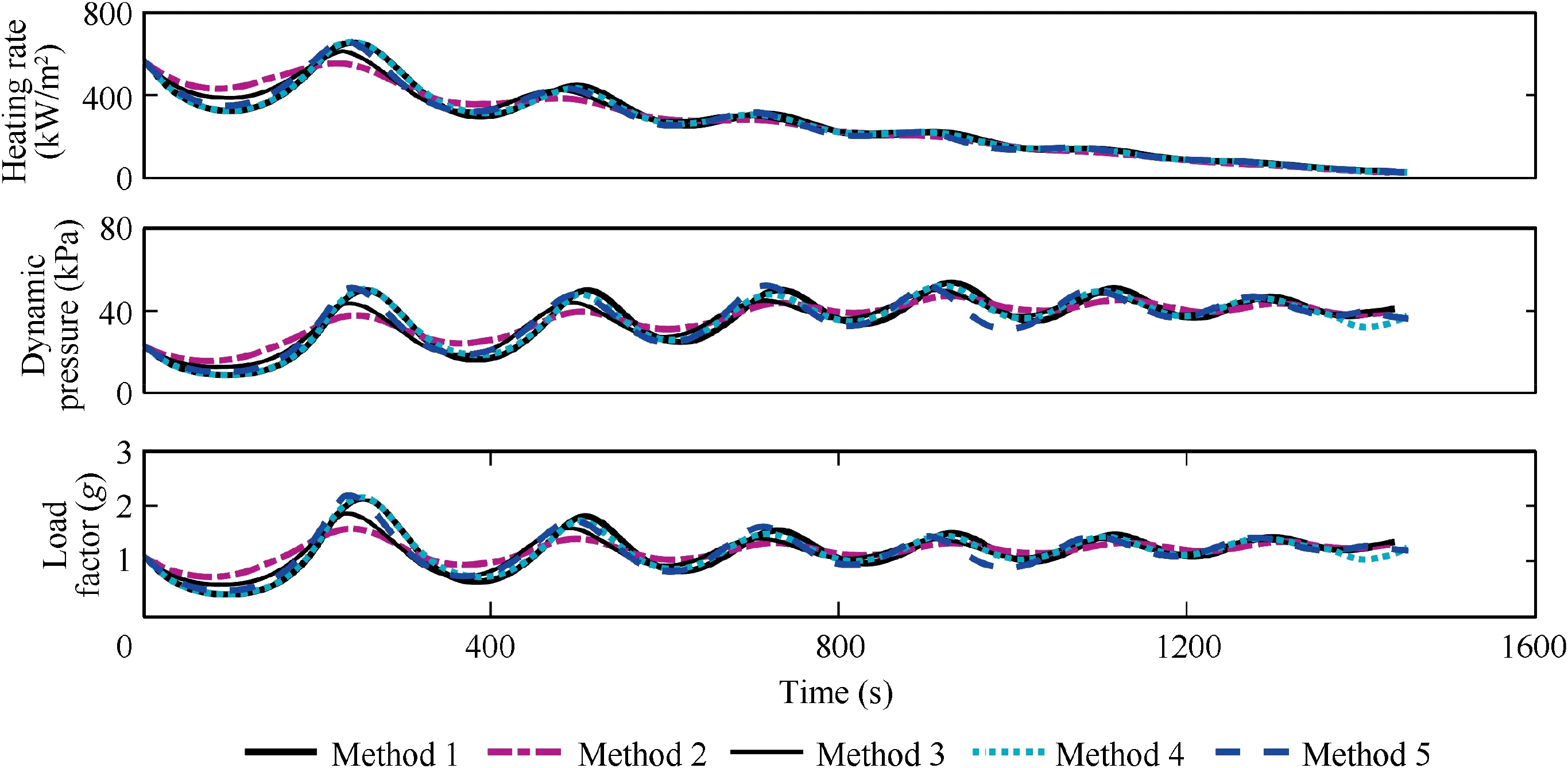
Fig. 13 Inequality path constraints profiles.
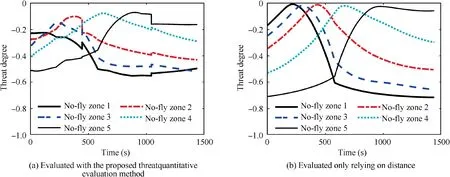
Fig. 14 Threat degree versus time profiles of each no-fly zone.
From Fig.10,it can be seen that there are mutations of the reference heading angle with Method 1. This is because the judgment criterion for whether a no-fly zone has been avoided is introduced in the proposed guidance algorithm.When a nofly zone satisfies the judgment criterion for whether a no-fly zone has been avoided, its repulsive potential field will be removed. From Figs. 7, 9 and 12, it is indicated that with Method 1, the no-fly zone 3 satisfies the judgment criterion for whether a no-fly zone has been avoided at 306 s and its repulsive potential field is removed.The vehicle’s heading deviates from the no-fly zone 2 under the action of the target’s attractive force and the repulsive forces of the no-fly zone 2 and 4.With Method 5,the function of the proposed judgment criterion is removed near no-fly zone 3, and although no-fly zone 3 has been avoided, its repulsive force still acts on the vehicle after 306 s. The vehicle continues to approach the no-fly zone 2 under the action of the resultant force until 372 s.However,at this time,the maneuverability of the vehicle has been exceeded, and no-fly zone 2 cannot be avoided.
From Figs.7,9 and 12,it also can be seen that the target is at the back of no-fly zone 5 and is very close to no-fly zone 5.By the judgment criterion for whether a no-fly zone has been avoided,the no-fly zone 5 has been avoided at 959 s.However,as the boundary of the no-fly zone 5 is close to the target, the no-fly zone 5 does not satisfy the judgment criterion once again at 1399 s.At this moment,the repulsive force of the no-fly zone 5 cannot be removed, and the vehicle should be steered to the target under the action of the resultant force of the target’s attractive force and the repulsive force of the no-fly zone 5.The judgment criterion for whether a no-fly zone has been avoided should be used throughout the flight. The above results indicate that the no-fly zones that have been avoided are accurately identified by the proposed judgment criterion.The improved artificial potential field proposed in this paper can accurately describe the relative positional relationship among the vehicle, the no-fly zones, and the target to determine the reference heading angle, and effectively reduce the superposition effect between potential fields. The inequality path constraints profiles of the vehicle with the above methods are shown in Fig.13.From Fig.13,it can be indicated that the heating rate,load factor and dynamic pressure are successfully satisfied in the flight.

Table 2 Dispersions in Monte Carlo simulation.
Fig. 14 compares the threat degree versus time profiles by the proposed threat quantitative evaluation method and the evaluation method only relying on the distance. From Fig. 14, it can be seen that the most threatening is the no-fly zone 1 at the beginning. Then, in Fig. 14(a), the threat degree of the no-fly zone 1 gradually decreases and starts to be less than that of the no-fly zone 3 at 128 s.This is because although the vehicle is gradually approaching no-fly zone 1, its heading is gradually pointing towards no-fly zone 3. However, in Fig. 14(b), the threat degree of no-fly zone 1 gradually increases at first and then gradually decreases, and is larger than that of no-fly zone 3 until 269 s. Similarly, all the most threatening no-fly zone changes in Fig. 14(b) lag behind those in Fig. 14(a). This is because the current heading angle of the vehicle and the relative position between the vehicle and no-fly zones are comprehensively considered in the proposed evaluation method.In fact,with the method only relying on distance,the most threatening no-fly zone will not change until the vehicle is away from this no-fly zone for quite a time,which usually leads to the failure to avoid the nearby no-fly zones,especially when multiple no-fly zones are closely distributed as shown in Fig. 7.
Moreover,from Fig.12 and Fig.14(a),it can be seen that at some time,although the no-fly zone has satisfied the judgment criterion for whether a no-fly zone has been avoided,its threat degree is still in the second or even the first place.For example,no-fly zone 4 has been avoided at 659 s,but its threat degree is still in the first place until 764 s.This proves the correctness of firstly finding out the no-fly zones that have not been avoided,and then sorting them by their threat degrees. The above simulation results show that the proposed threat quantitative evaluation method can accurately describe the threat degree of nofly zones. The guidance logic via improved dynamic heading corridor proposed in this paper is highly sensitive to the nofly zone’s threat changes and can meet the requirements of complex distributed no-fly zones avoidance.
Based on the simulation results and the discussion above,it can be indicated that the proposed lateral reentry guidance algorithm has practical applicability in complex distributed no-fly zones avoidance missions and can satisfy the requirements of multiple closely distributed no-fly zones avoidance.
5.3. Testing for dispersed cases
In the reentry process, the uncertainties of the atmospheric model, the strong disturbances in the dynamic system, and the strong disturbances of the vehicle’s initial state may cause the vehicle to deviate from the initial trajectory or the target,and even lead to failure of the mission. Therefore, the proposed lateral reentry guidance algorithm is tested under reentry dispersions to verify the robustness in 200 flights. In this study,perturbations of the initial states,the aerodynamic coefficients, the atmospheric density, and the vehicle’s mass are considered in simulations.All of the perturbations obey Gaussian distribution, and the amplitude of each perturbation is given in Table 2.
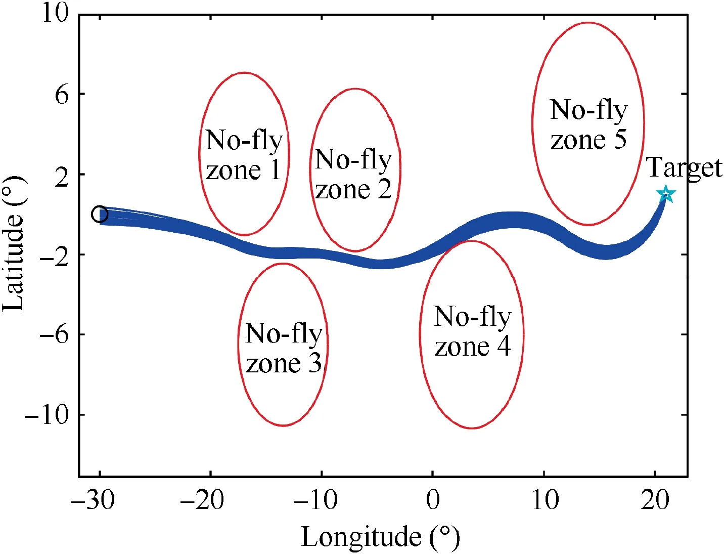
Fig. 15 Ground tracks for 200 dispersed cases.
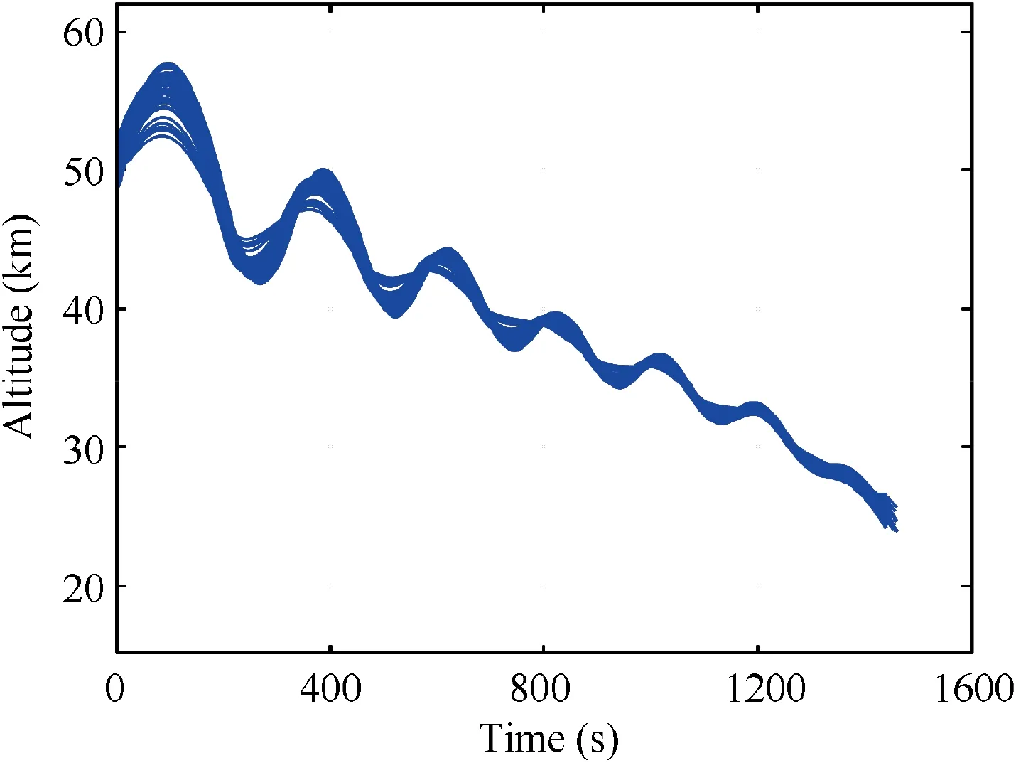
Fig. 16 Altitude histories for 200 dispersed cases.
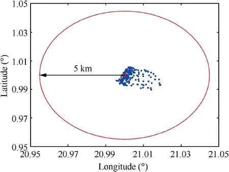
Fig. 17 Terminal locations distribution for dispersed cases.
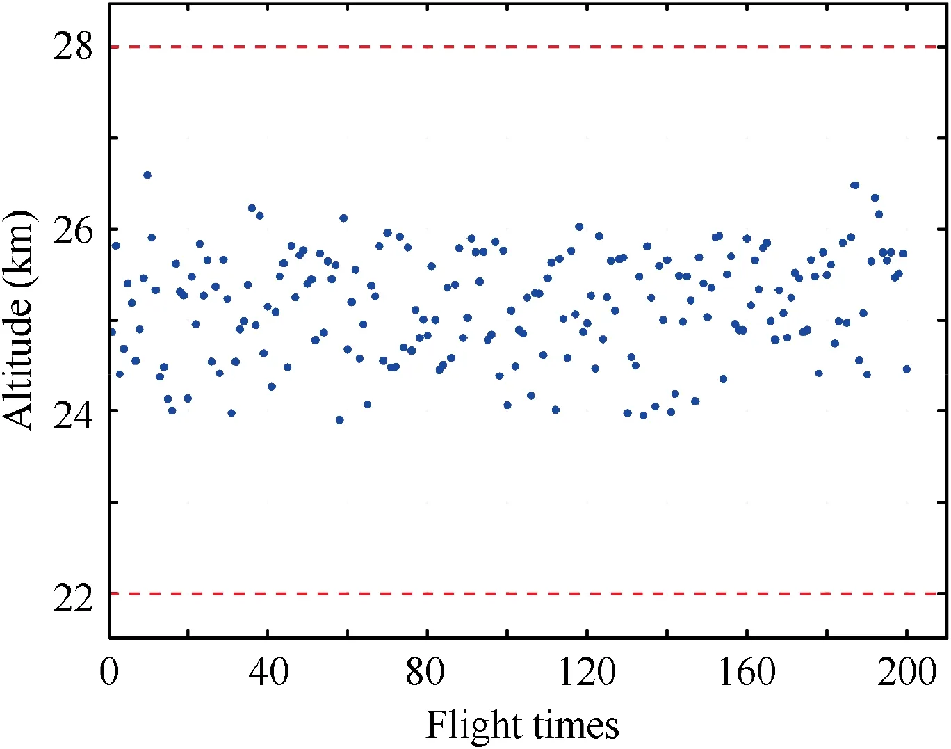
Fig. 18 Terminal altitudes distribution for dispersed cases.
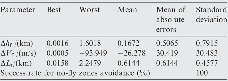
Table 3 Statistical results of terminal errors.
The simulation results for dispersed cases are shown in Figs.15–18.Ground tracks and altitude histories for dispersed cases are shown in Fig. 15 and Fig. 16, respectively. From Fig. 15, it can be seen that under the disturbance conditions,the proposed guidance method can successfully guide the vehicle to the target and avoid all the closely distributed no-fly zones. The success rate of the no-fly zones avoidance is 100%. Fig. 17 depicts the terminal locations for 200 dispersed cases.Fig.18 shows terminal altitudes for 200 dispersed cases.Statistical results of terminal errors are given in Table 3. As shown in Table 3, terminal distances to the target point are within 3.0 km, and the maximum and mean terminal distance errors are 2.2479 km and 0.6144 km,respectively.The terminal locations are mainly distributed in the southeast, which is due to the influence of no-fly zone 5. From Fig. 18 and Table 3, it can be indicated that terminal altitude errors are within 2 km,and the maximum and mean terminal altitude errors are 1.6018 km and 0.5065 km, respectively. The maximum and mean terminal velocity errors are - 93.949 m/s and 30.419 km/s, respectively. From Fig. 17, Fig. 18 and Table 3,it can be indicated that the distributions of terminal errors are stable and concentrated. The simulation results for dispersed cases show that the proposed guidance algorithm has high robustness and stability.
The simulation results for nominal and dispersed cases have indicated that the proposed lateral reentry guidance algorithm has high applicability, robustness, and stability. This lateral reentry guidance algorithm is a feasible and effective method to deal with complex distributed no-fly zones avoidance problems.
6. Conclusions
The present work aims at developing a novel lateral reentry guidance algorithm for hypersonic glide vehicles to deal with complex distributed no-fly zones avoidance problems.The reference heading angle determination problem under the constraints of complex distributed no-fly zones is solved with the developed improved artificial potential field method. The proposed judgment criterion for whether a no-fly zone has been avoided is proposed and introduced in improved artificial potential field method and the guidance logic to simplify the flight environment as much as possible. A novel no-fly zone threat quantitative evaluation method is presented to accurately evaluate the threats of no-fly zones and is applied to improve the heading corridor for enhancing its sensitivity to the threat changes of the no-fly zones. A novel guidance logic via improved heading corridor is developed and adopted to update the reference heading corridor adaptively in real time according to the threat and constraint changes of the no-fly zones to satisfy the requirements of complex distributed nofly zones avoidance. Then the bank reversal logic is employed to control the lateral motion for avoiding the no-fly zones and guiding the vehicle to the target.The applicability,robustness,and stability of the proposed lateral reentry guidance algorithm are validated by the simulations for nominal and dispersed cases. The simulation results show that the proposed lateral reentry guidance algorithm is a feasible and effective method to deal with complex distributed no-fly zones avoidance problems.
The authors declare that they have no known competing financial interests or personal relationships that could have appeared to influence the work reported in this paper.
This study was supported by the National Natural Science Foundation of China (No. 12072090).
 Chinese Journal of Aeronautics2022年7期
- Chinese Journal of Aeronautics的其它文章
- An online data driven actor-critic-disturbance guidance law for missile-target interception with input constraints
- Study on excitation force characteristics in a coupled shaker-structure system considering structure modes coupling
- Smooth free-cycle dynamic soaring in unspecified shear wind via quadratic programming
- Active and passive compliant force control of ultrasonic surface rolling process on a curved surface
- High dynamic output feedback robust control of hydraulic flight motion simulator using a novel cascaded extended state observer
- Composite impact vector control based on Apollo descent guidance
