Composite impact vector control based on Apollo descent guidance
Kory S. ERER, Rziye TEKIN,*, M. Keml O¨ ZGO¨ REN
a Tactical Missile Systems, Roketsan Missiles Inc., Elmadag˘06780, Turkey
b Department of Mechanical Engineering, Middle East Technical University, C¸ankaya 06800, Turkey
KEYWORDS Impact angle;Impact plane;Impact vector;Three-dimensional missile guidance;Trajectory shaping
Abstract A new three-dimensional missile guidance law to control the impact vector against a stationary target is proposed. The composite guidance law has two well-known components: Apollo descent guidance and trajectory shaping guidance. These respectively linear and planar guidance laws are combined to achieve a specified impact direction. The main idea is to define an impact plane and to steer the missile onto this plane using Apollo descent guidance while concurrently performing trajectory shaping with reference to the impact plane. The resulting guidance law is expressed by a single equation in vector form, which is straightforward to implement. Because it originates from an optimal formulation, the performance of the proposed technique is expected to be satisfactory.This is confirmed by comparative simulation runs,which also involve the method known as generalized explicit guidance.
1. Introduction
The ability of approaching the target from a specified direction is a valuable asset in missile applications. The benefits include avoiding directional defense mechanisms and being able to capture targets that would otherwise be missed. Understandably,this specific topic of missile guidance has attracted much interest in the literature.In classical missile guidance,in which the sole objective is usually to reduce the miss distance,Proportional Navigation (PN) is an indispensable tool. However, when there is the additional constraint of impact angle present, alternative approaches need to be devised.
In the literature, PN-based and control-theoretic approaches are commonly adopted for the solution of the impact-angle control problem. For example in Ref. 1, the PN law is enhanced with the addition of a bias term as a function of the range to go.A two-phased guidance scheme is proposed in Ref. 2, where the objective of the first phase is to provide proper initial angular conditions for the second phase that is governed by PN. Another switched-gain PN scheme is developed in Ref.3 under the look angle and acceleration constraints.Ref.4 solves the impact-angle problem through a geometrical three-point guidance method without the need for the Line-of-Sight(LOS)rate signal.In Ref.5,an optimal solution is proposed by setting out with a biased PN command with continuous feedback. Ref. 6 compares unbiased and biased formulations of PN including the look angle constraint. A dynamic optimization problem is converted to a static optimization problem in an iterative manner in Ref. 7. The same performance index was considered in Ref.8 to derive guidance laws to be used by lag-free and first-order systems,and a timeto-go estimation method is also presented.A control law based on the state-dependent Riccati equation,which is a function of both the range to go and the time to go, is obtained in Ref. 9.In Ref.10,which presents a sliding-mode guidance and control approach, the guidance command has two components for reaching and remaining on the sliding surface.
In spite of the popularity of the subject,the number of studies focusing on impact vector control are far smaller than that of studies focusing on impact angle control. This is probably because of the more challenging nature of the Three-Dimensional (3D) kinematics. One relatively early example of such an effort is the generalized vector explicit guidance(GENEX)presented in Ref.11,where a linear optimal control problem is solved and the resulting guidance law is then extended to have a vector form. Another early example can be found in Ref. 12, which addresses the problem by applying PN in the horizontal and vertical channels by updating the navigation gains in an adaptive manner. In Ref. 13, the method of partial integrated guidance is applied,where sliding mode control is utilized to handle uncertainties. The work in Ref. 14 applies model predictive static programming by also considering the control saturation and the autopilot lag. Ref.15 derives a fixed-time convergent guidance structure based on sliding mode control. Ref. 16 extends its planar impact angle solution to 3D via orienting the pursuer’s velocity vector onto a preferred maneuver plane and the impact angle vector is achieved within a three-phased command structure.In Ref.17,a Lyapunov-based solution is proposed considering coupled kinematics.
With the exception of Ref. 11, none of these 3D studies(and a number of others in the literature)involves a‘‘guidance law” with the classical meaning of the term, which refers to a single, standalone equation that can directly be coded in the guidance algorithm. The current study aims to address such need.In this work,a Composite Impact Vector(CIV)guidance approach,in which two readily available control strategies are integrated, is considered for the control of the 3D impact vector against a stationary target. The proposed guidance law is composed of two vector components orthogonal both to each other and to the velocity vector. The first component is the‘‘Apollo descent” guidance law, which is the linear optimal guidance law that was used to land the Apollo spacecraft on the moon. The other component, namely the ‘‘trajectory shaping” guidance law, which is also borrowed from Ref. 18,is in fact the same guidance law with a different final condition and expressed in a nonlinear planar form.
The backbone of the formulation is the impact plane that is constructed to include the desired impact vector. The task of the Apollo descent guidance is to pull the missile towards this impact plane in such a way that the missile arrives at the plane the same moment it arrives at the target. This simultaneity,which is achieved by virtue of utilizing the time to go, is a design choice;the missile could be made to reach the plane earlier at a designated time, but this was found to yield unfavorable results and hence avoided.On the other hand,the task of the trajectory shaping guidance is, as the name indicates, to shape the trajectory with reference to the impact plane. Here,the term‘‘with reference to”does not mean‘‘in”since the missile will reach the impact plane only at the final time. It is to mean that the trajectory shaping guidance utilizes the component of the LOS rate vector about the plane’s normal.
In what follows, the concept of 3D guidance by using an impact plane is introduced first. The general equations of the engagement and those specific to the proposed strategy are then given in the same section.In the third section,the derivations of the Apollo descent and trajectory shaping guidance laws are presented for the sake of completeness. The fourth section explains how the guidance concept can be mechanized by combining the Apollo descent and trajectory shaping guidance laws. As mentioned above, the result is a single equation that represents the CIV guidance law in vector form.An angular limitation of the method is also revealed there.The last section is reserved for numerical simulations, in which a comparison with GENEX is performed.
2. Guidance concept
The 3D geometry of the engagement between a missile M with a velocity vector v and its stationary target T is depicted in Fig. 1. This figure will help summarize the logic of the proposed guidance concept. As seen, an impact plane, which lies perpendicular to the horizontal plane that is formed by the basis vectors uand u, is defined by the desired impact direction uand the basis vector u. The impact direction is constructed through the azimuth angle ψ and the elevation angle θ. By decreasing the distance y along the plane’s normal defined by u, the missile is expected to converge onto this impact plane at the end of the engagement. When the missile reaches the plane,it is expected to do so with its velocity vector pointing at the impact direction. This objective is achieved by shaping the trajectory in a direction perpendicular to the plane’s normal. The LOS angle between the impact direction and the line joining the target’s position with the missile’s projected position is denoted by λ.
For such an engagement, the following general equations can be written. First, the relative position of the target with respect to the missile is
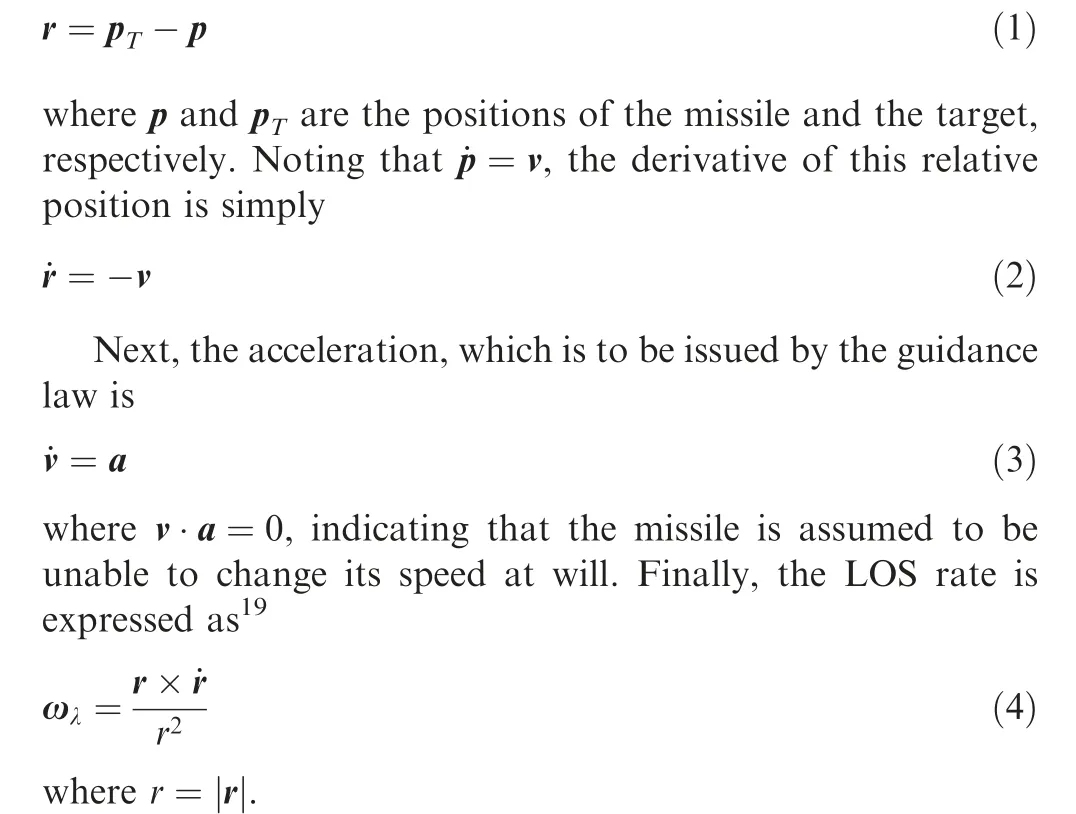
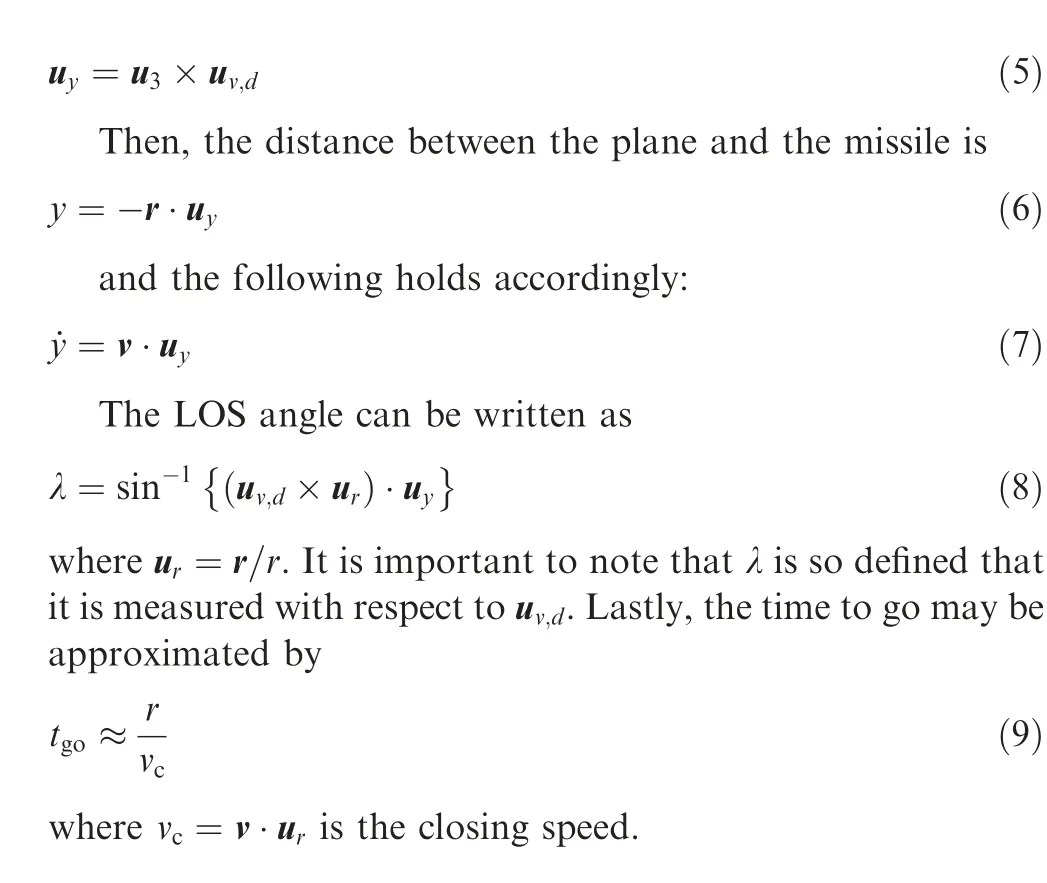
Now,specific equations required for implementation will be presented. The normal to the impact plane can be obtained through the cross product
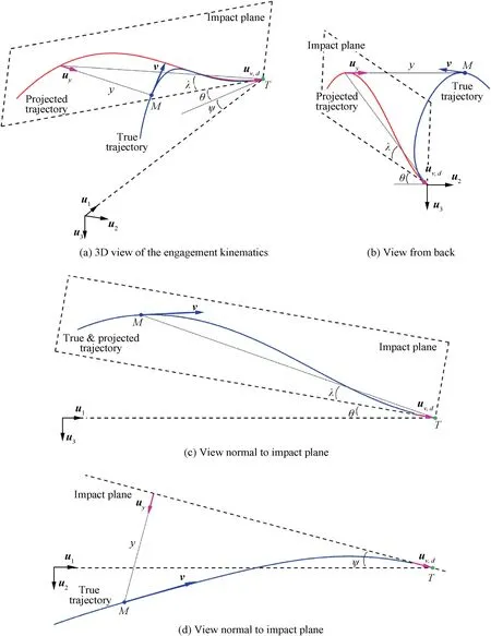
Fig. 1 Explanation of proposed guidance scheme with help of different views.
3. Derivation of the guidance laws
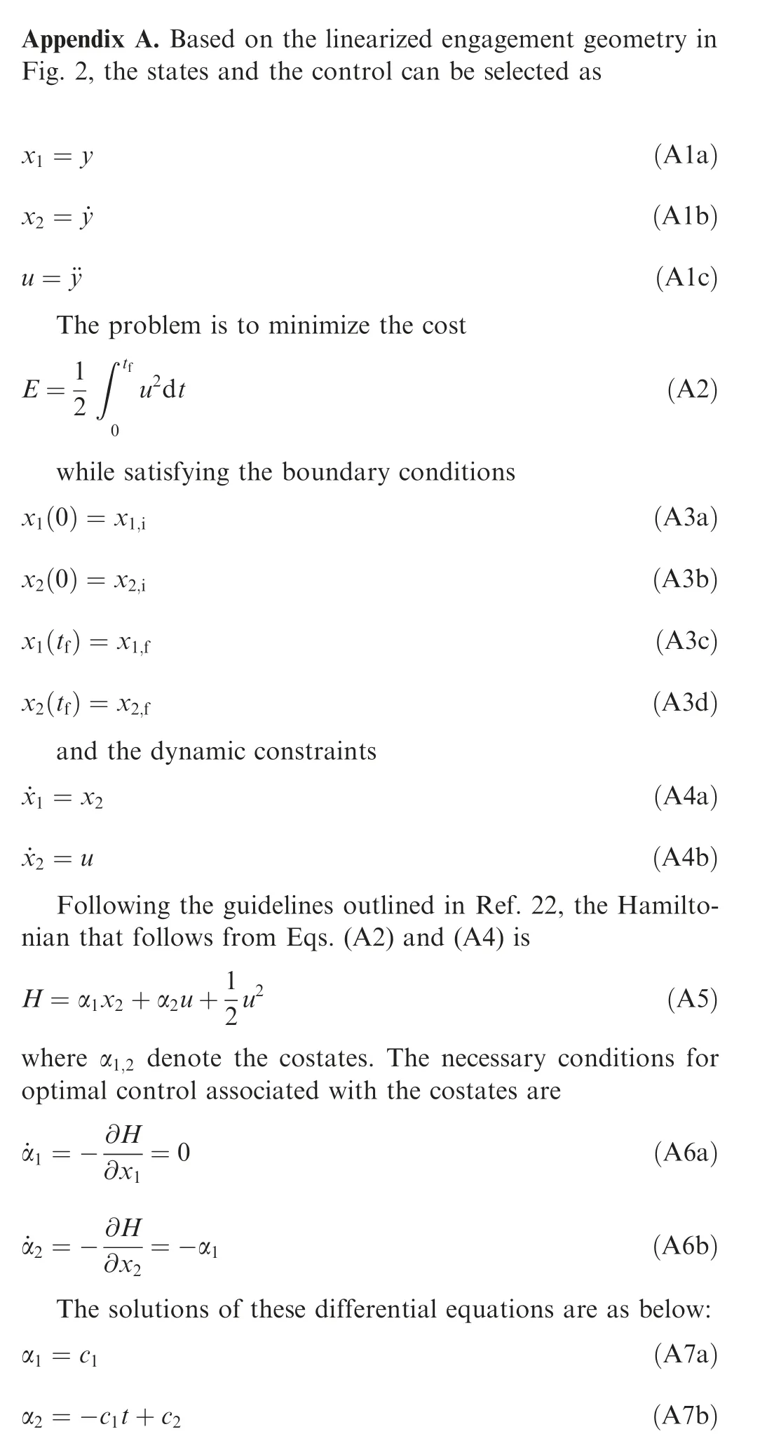
As elaborated in the previous section, two guidance laws are required to implement the concept: one to reach the impact plane and another to shape the trajectory with reference to the same plane. The approach adopted in this work is to employ the Apollo descent and trajectory shaping guidance laws borrowed from Ref. 18, where the optimal control problem is solved through the use of Schwarz inequality. Here, an alternative derivation based on the solution of the two-point boundary problem will be presented.
The linear engagement geometry depicting the missile approaching the target is given in Fig. 2. In addition to the symbols defined in the previous section; γ is the missile’s flight path angle and tis the final time. The range to go is expressed as v(t-t). Based on this geometry, the following are true:

Fig. 2 Linearized engagement geometry.
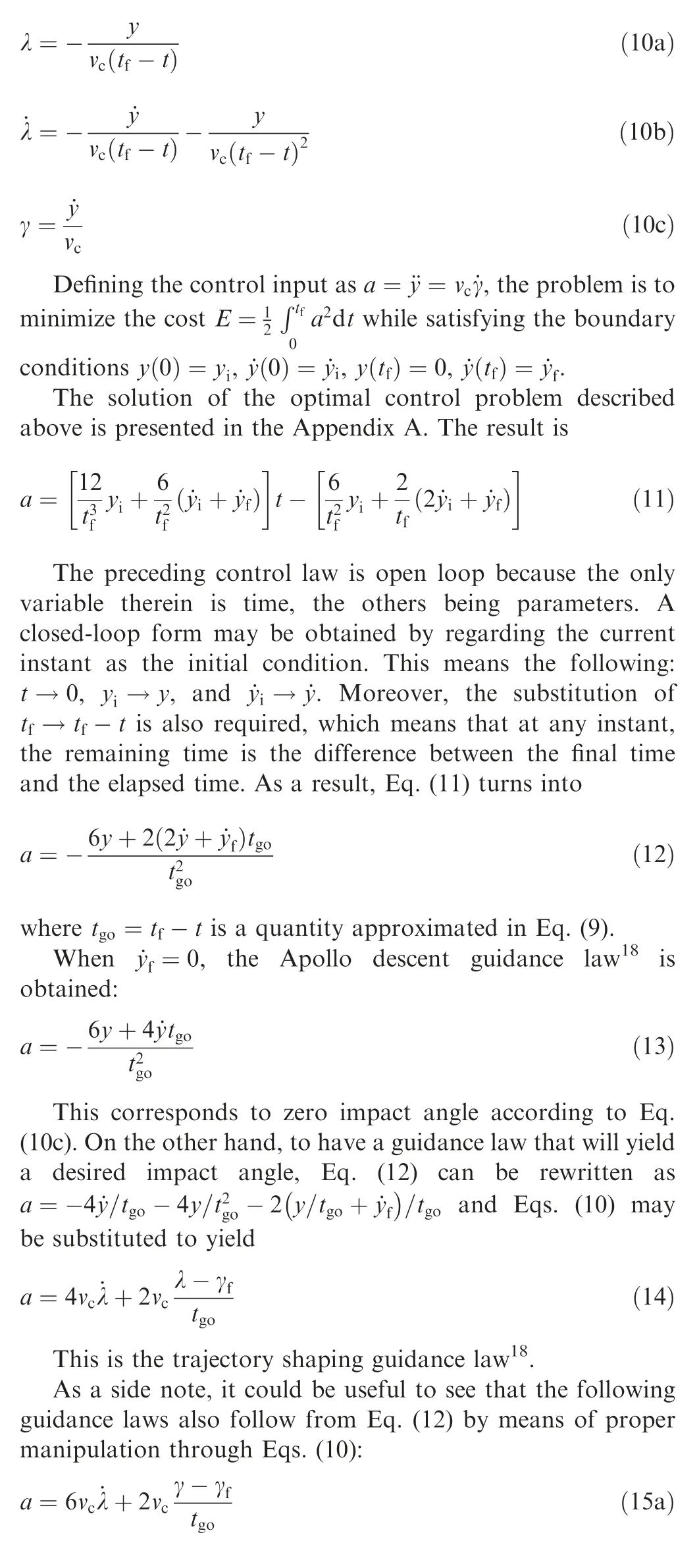

These are from Ref.20,Ref.16,and Ref.21,respectively.It is interesting that the coefficients of the LOS rate are not the same in Eq. (15a) and Eq. (15b), and there is no LOS rate at all in Eq. (15c). Before proceeding, it should be noted that any guidance law from Eqs. (15) could be used to shape the trajectory; yet the planar counterpart of the Apollo descent guidance derived in the same Ref. 18 is preferred in this work to maintain consistency.
4. Mechanization of the guidance concept
It is known that the Apollo descent guidance law can bring a vehicle to rest (y= ˙y=0) from an arbitrary initial condition.Therefore, it would be particularly suitable for the objective of reaching the impact plane as described Section 2.While this is so,Eq.(13)needs to be given a sense of direction in order to function in 3D space. This is readily achieved by
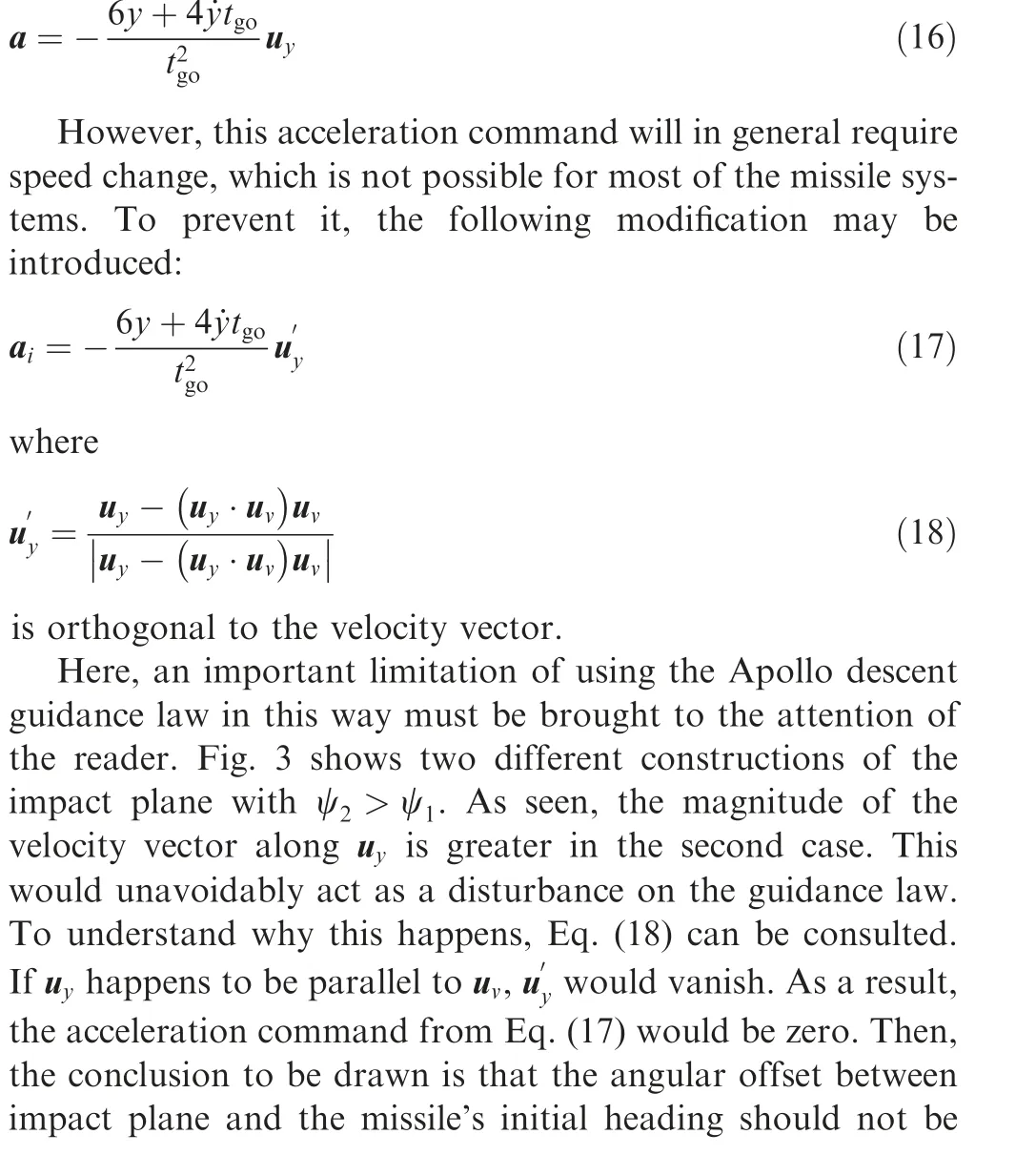
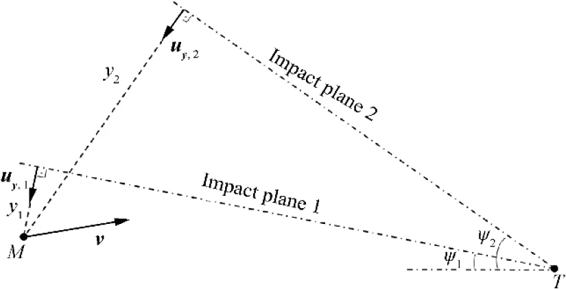
Fig. 3 Effect of increased azimuth demand.
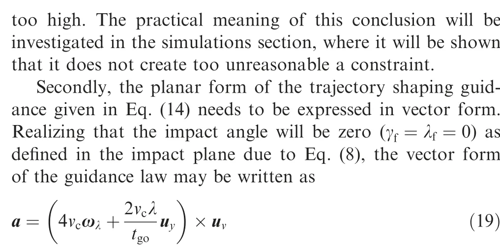
However,this guidance law has a subtle internal contradiction, which might not be conspicuous at first sight. There are two planes that are relevant to Eq. (19): The first one is the instantaneous plane formed by the LOS and velocity vectors.The PN term, that is ω×u, would want to remain in this PN plane as detailed in Ref. 16. The second one is the impact plane with its normal u. The trajectory shaping term, that is u×u, would act as a disturbance for the first term because it tries pull the missile away from the instantaneous PN plane.Therefore, the following modified form is proposed
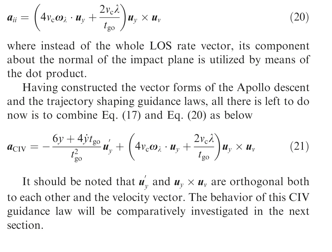
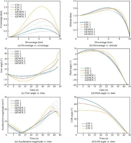
Fig. 4 Simulation results under ideal conditions.
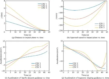
Fig. 4 (continued)
5. Simulation
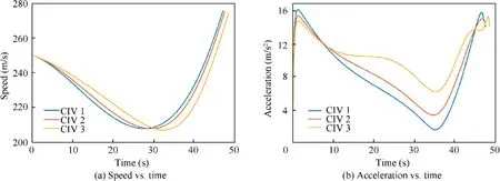
Fig. 5 Simulation results under disturbance.
Fig. 5 presents the results of the simulations performed under disturbance, where there is gravity, drag, and autopilot lag.The deceleration due to drag is modeled as-1.4×10νand the autopilot is represented by a first-order lag of 0.3 s on acceleration response. Also, the guidance command is held constant during the last 50 m to emulate a saturated seeker.Here, only the speed and acceleration variations of the missile are presented because doing otherwise would not add much on top of what is already made available in Fig.4.The speed profiles drawn in Fig. 5(a)show that the missile firstly decelerates with increasing altitude and then it accelerates until the target is hit.In Fig.5(b),the acceleration profiles can be investigated.The effect of gravity is apparent in comparison with Fig. 4(e).The missile initially expends more effort to resist gravity and then receives assistance during the descent. It is important to note that the acceleration profile of the third scenario is less smooth than the other ones. This expected behavior is associated with the angular limitation of the CIV guidance law previously elaborated with the help of Fig. 3.
6. Conclusions
The 3D guidance technique proposed in this study attempts to solve the problem of impact vector control. The associated guidance command in vector form is composed of two different versions of the same optimal control law.The first component is the Apollo descent guidance law, which is responsible for reaching the impact plane that is defined according to the desired impact vector.The second component is the trajectory shaping guidance law, which is utilized to achieve zero LOS angle at the time of impact. Some simple modifications are introduced so that these two guidance laws can coexist and will not require speed change. Due to the nature of the problem geometry, the performance of this CIV guidance law starts degrading with increasing azimuth angle demand.Fortunately,the simulation results show that the method still functions well for azimuth values as high as forty-five degrees, which indicates potential usefulness for practical applications. Future studies will focus on the development of an improved methodology.
The authors declare that they have no known competing financial interests or personal relationships that could have appeared to influence the work reported in this paper.
 Chinese Journal of Aeronautics2022年7期
- Chinese Journal of Aeronautics的其它文章
- An online data driven actor-critic-disturbance guidance law for missile-target interception with input constraints
- Study on excitation force characteristics in a coupled shaker-structure system considering structure modes coupling
- Smooth free-cycle dynamic soaring in unspecified shear wind via quadratic programming
- Active and passive compliant force control of ultrasonic surface rolling process on a curved surface
- High dynamic output feedback robust control of hydraulic flight motion simulator using a novel cascaded extended state observer
- Optimal trajectory design accounting for the stabilization of linear time-varying error dynamics
