Optimal trajectory design accounting for the stabilization of linear time-varying error dynamics
Ptrick PIPREK, Hicho HONG,*, Florin HOLZAPFEL
a Institute of Flight System Dynamics, Technical University of Munich, Garching D-85748, Germany
KEYWORDS LTV error dynamics;LTV stability;Optimal control-based LTV stabilization;Path-following error controller;Trajectory generation;Trajectory optimization
Abstract This study is dedicated to the development of a direct optimal control-based algorithm for trajectory optimization problems that accounts for the closed-loop stability of the trajectory tracking error dynamics already during the optimization. Consequently, the trajectory is designed such that the Linear Time-Varying(LTV)dynamic system,describing the controller’s error dynamics, is stable, while additionally the desired optimality criterion is optimized and all enforced constraints on the trajectory are fulfilled.This is achieved by means of a Lyapunov stability analysis of the LTV dynamics within the optimization problem using a time-dependent, quadratic Lyapunov function candidate.Special care is taken with regard to ensuring the correct definiteness of the ensuing matrices within the Lyapunov stability analysis,specifically considering a numerically stable formulation of these in the numerical optimization.The developed algorithm is applied to a trajectory design problem for which the LTV system is part of the path-following error dynamics, which is required to be stable. The main benefit of the proposed scheme in this context is that the designed trajectory trades-off the required stability and robustness properties of the LTV dynamics with the optimality of the trajectory already at the design phase and thus,does not produce unstable optimal trajectories the system must follow in the real application.
1. Introduction
The optimal control-based design of trajectories is widely used in engineering applications.This paper investigates an efficient trajectory design by optimization that additionally accounts for the closed-loop stability and robustness of a trajectory tracking error controller, described by Linear Time-Varying (LTV) dynamics, required in real application scenarios.Often, the trajectory and the feedback controller are designed separately. This is generally not ideal, as it may require the optimal trajectory to be conservative, i.e., in this context a ‘‘sub-optimal” trajectory resulting e.g., by reducing the allowed value-range of the constraints, for the controller to follow it.On the other hand,if the trajectory is very aggressive, i.e., at its theoretical optimum obtained from an optimization with the least amount of constraints and limitations,the controller may be required to be conservatively designed to control the system in a stable manner.Thus,compared to designing trajectory and controller independent of each other,designing them in a single setup facilitates the performance of the designed optimal trajectory and increases the availability of trajectories in the real application.This is based on the fact that the optimizer only returns a solution if the setup can be solved with all its constraints,which contain both the physical model (like acceleration limits) as well the controller constraints (like stability and gain magnitude) in the single setup. In contrast, if the controller is designed independent of the trajectory,further(on-board)testing by e.g.,simulations,may be required to ensure that only trajectories that do not de-stabilize the controller are commanded. Thus, to formulate the single setup and ensure feasible trajectories, the error dynamics used in designing the feedback controller,which are often of a LTV system type, must be stabilized using suitable constraints already inside the trajectory optimization problem.
Thus,this study is dedicated to the development of a direct optimal control-based algorithm (i.e., gradient-based) for trajectory optimization problems that directly accounts for the stability of a dependent LTV dynamic system by means of Lyapunov stability. Consequently, the trajectory is designed such that the incorporated LTV dynamics are ensured to be stable and fulfill specified robustness features, based on the convergence rate of the Lyapunov function,by designing feedback gains in the optimization, while additionally the desired optimality criterion is optimized and all enforced constraints on the trajectory are fulfilled. This automatically provides a trade-off between the optimality of the trajectory and the required stability of the LTV system by designing both parts dependent on each other.
In general, assessing the stability of LTV systems was always of paramount importance in Refs. [6–8]. Compared to well-known Linear Time-Invariant (LTI) controller design,it is no longer given by simply checking the eigenvalues of the state matrix.Therefore, methods often avoid the design of controllers for LTV systems, but rather design the controller by gain scheduling methods, i.e., designing the gains for LTI systems at a sufficiently dense grid of parameter sets.Although this approach generally yields good results, a drawback is that it only produces stable controllers if the timedependent changes are sufficiently slow, i.e., the problem is in a quasi-steady state.As trajectory optimization often results in aggressive maneuvers and thus, fast time-dependent changes, this assumption may no longer be valid.
To cope with this issue, researcher investigated optimal control and especially convex trajectory optimization for LTV systems. A review of common methods was given in Ref. [10]. Here, specifically model predictive control algorithms play an important role: For instance, Ref. [11] introduced an algorithm to represent a nonlinear dynamic model using sequential linear parameter-varying representations that are then used within the convex optimization.By this,feasibility and stability of the controller can be ensured. In this context, Ref. [12] introduced further methodologies to cope with constrained optimization of linear parameter-varying systems.Finally, Ref. [13] introduced a method for output feedback controller design based on parameter-dependent Lyapunov functions.
Considering the literature review, it is clear that stabilizing LTV systems,especially for error controllers as well as designing feedback controller gains for these, is of high importance.Still,studying the impact of LTV systems already in the trajectory design phase has not yet been thoroughly researched.Therefore, this study aims at bridging this gap by considering the stability of LTV systems already in the trajectory design phase. In addition to basic stability, it is also possible to enforce desired convergence and robustness requirements on the Lyapunov function,and thus the controller,as constraints in the optimization problem.Here,it is important to stress that this study does not try to invent new methods to stabilize LTV systems, but uses well-established stability concepts as a baseline to develop a design procedure for trajectory optimization accounting for the stabilization of a dependent LTV system.Generally, this goal is achieved by introducing the LTV dynamics within the trajectory optimization problem, which is used to calculate the desired, feedforward trajectory that the dynamic system should follow. By incorporating these LTV dynamics and imposing constraints to address stability,it is ensured that the trajectory design is already ensuring stable operation by itself.Thus,the feedback controller,which can be designed simultaneously, is not required in the real application to stabilize an unstable designed trajectory but can focus on disturbance rejection and coping with nonmodeled dynamics. Furthermore, by incorporating the controller design within the trajectory generation by means of Lyapunov stability analysis, it is also possible to generalize the results of feedback controller gain design from the open left complex plane, as e.g., done in gain scheduling applications,to the full complex plane. This is due to the fact that LTV systems do not have such a limiting requirement. Still,stability of the system within assured convergence bounds is ensured. Even further, these can be used to improve the robustness of the solution by introducing them as constraints in the optimization problem. By this, it can be assured that the Lyapunov function and its derivative follow e.g.,a minimal convergence rate and thus, the error reduces with at least this rate. In this context, special care is taken in the proposed method with regard to ensuring the correct definiteness of the matrices within the Lyapunov stability analysis,specifically considering a numerically stable formulation for the gradientbased optimization.
The contributions of the presented work can therefore be summarized as:
(1) An optimal control-based trajectory design method is proposed, which accounts for the stability of a tracking controller described by LTV dynamics already within the optimization problem. This provides a trade-off between the required stability of the controller and the optimality of the trajectory.
(2)The closed-loop stability of the trajectory tracking error controller, i.e., the LTV-type error dynamics, is already guaranteed in the design phase by appropriately designing a trajectory and the associated feedback gains automatically in an optimal manner.
(3) The sufficient conditions of the desired stability are derived based on the mathematical properties of the Lyapunov method,which are implemented as simple inequality constraints in the optimal control problem.This reduces the overall design complexity, leading to a very pragmatic and effective design process.
(4) The closed-loop robustness, in the sense of e.g., a minimal convergence rate of the Lyapunov function and its derivative, and by this consequently the tracking error, is ensured using constraints in the optimization problem. By this, a desired performance of the controller can be achieved in connection with the designed optimal trajectory.To introduce the mentioned concepts, this study is organized as follows:Section 2 introduces the general idea of stability analysis for LTV systems. These principles are used in Section 3 to formulate suitable constraints within a gradientbased trajectory optimization problem. Following, Section 4 gives an application example: Here, Section 4.1 gives an overview on the LTV error dynamics used in this study to illustrate the introduced stability concept within trajectory optimization.Building on these error dynamics, Section 4.2 gives an overview of methods to stabilize them by means of feedback control. Furthermore, the dynamic model as well as the trajectory optimization problem formulation with stabilization of the feedback controller is specified in Section 4.3. The results of the trajectory optimization problem as well as an analysis of the controller performance is shown in Sections 4.4 and 4.5, respectively. Concluding, Section 5 gives some remarks and an outlook on future work.
2. Stability analysis of linear time-varying systems
Generally,a LTV system,with state vector e(t )∊R,is defined in this study as follows:
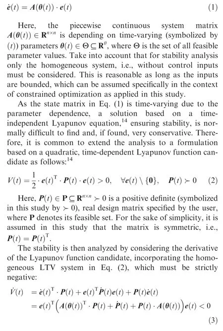

Here, the matrix Q(t )∊ Q ⊆R≻0 must be positive definite,where Q defines its feasible set.Because of the requirement in Eq. (4), the well-known result for LTI systems, i.e.,that the eigenvalues of the matrix A(θ(t )) must be located in the open-left complex plane, is no longer a sufficient criterion for stability. Indeed, it is not even necessary as there are LTV systems with eigenvalues of the dynamic matrix in the right complex plane that are stable,while there are also systems with only eigenvalues of the dynamic matrix in the left complex plane that are unstable.Removing this eigenvalue constraint, which may e.g., limit the possible gain value combinations,of classical gain scheduling approaches operating on LTI systems is also one of the contributions of this paper within the connected view on the trajectory optimization as well as LTV error dynamics stabilization,as it allows an improved exploitation of the system capabilities within numerical optimization.It should be noted in this context that Eq. (2) is still a conservative formulation for an LTV system as the Lyapunov matrix P(t ) is only time-dependent rather than parameter-dependent and thus, the equation must be fulfilled for all parameters and their time derivatives and not just the ones that are encountered and physical.Still, it is common to use this time-dependent approach to remain valid for generic LTV system formulations. However, it is important to stress that the proposed algorithm is not limited to the quadratic, timedependent Lyapunov function candidate in Eq. (2), but can also be evaluated using any other suitable candidate function.
In the context of analyzing the convergence and stability properties of the LTV system based on the Lyapunov method,it is important to note that the time-varying Lyapunov function candidate in Eq. (2) can be bounded as follows:
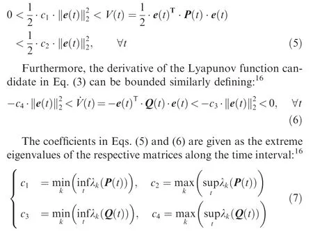
Here, λ(∙) is the k-th eigenvalue of the respective matrix evaluated at each time instance independently by solving a classic eigenvalue problem.Thus, the time-varying Lyapunov function candidate and its derivative may be bounded by a static, time-independent analysis of the properties, and especially the eigenvalues, of the corresponding matrix. This property is used in Section 4.5 to validate the performance of the controller in the application example. Furthermore, these bounds are used to provide constraints in the optimization problem to e.g., enforce a lower bound on the minimal error convergence rate and thus, to ensure robustness and a desired performance of the designed feedback controller.
3. Linear time-varying stability analysis within trajectory optimization
Section 2 introduced the basic principles of analyzing the stability of an LTV system using quadratic, time-dependent Lyapunov functions. The introduced methods must now be connected within a trajectory optimization problem as the stability of the LTV system should already be ensured when calculating the optimal trajectory. By this, an optimal trajectory that automatically accounts for the stability requirements of the dependent LTV systems,which may be the error dynamics of a path-following controller, is calculated. To stabilize the LTV system inside numerical gradient-based trajectory optimization, the required formulation of the Lyapunov stability analysis for trajectory optimization is introduced in the following,such that it can be solved numerically stable and efficient.
At first, Eq. (4) is a central equation required to verify the stability of the LTV dynamics in Eq.(1)within trajectory optimization. Consequently, the following matrix Equation of Motion (EoM) is added to the trajectory optimization problem:
˙P(t )=-Q(t )-A(θ(t ))∙P( t )-P(t )∙A(θ(t )) (8)
Thus,the entries of the matrix P t( )become states within the optimization problem,while the matrix entries of Q(t )are considered as free variables within the optimization.
Furthermore, it is important to note that the matrices P(t )and Q(t ) in Eq. (8) must be ensured to be positive definite within the trajectory optimization problem. One option to do this,comprises the methods of‘‘determinant-based”analysis of the matrices based on e.g.,the Routh-Hurwitz criterionor Sylvester’s criterion.A drawback of these is that they require the calculation of considerably large determinants including their derivatives in each iteration of the optimization. Additionally, the magnitude of the determinant values(especially when using the Sylvester’s criterion) varies significantly(i.e.,the magnitude of the determinant of the full matrix is normally much larger than the magnitude of only one entry),which generally leads to a numerically ill-conditioned optimization problem. Therefore, this study employs a constraint based on the idea of the Cholesky factorization as an alternative to create positive definite matrices. First of all, the Cholesky factorization for the matrix Q t( ) is defined as follows:
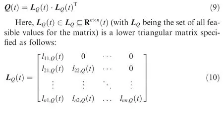
Now, Q(t ) is positive definite if, and only if, the diagonal entries of L(t )are real and have the same sign.Thus,the positive definiteness of Q(t )may be ensured by enforcing all signs of the diagonal entries of L(t ) to be strictly positive with a user-defined threshold ε, which requires the following constraint within the optimization problem:

Thus, the positive definiteness of Q (t ) in Eq. (8) can be ensured in constrained optimization by specifying the matrix entries of Lt( ) as real optimization variables, including the constraint on the diagonal elements in Eq. (11), rather than by using the matrix Q(t ) directly. This matrix can, however,be directly calculated based on Cholesky factorization definition in Eq. (9). This procedure is generally numerically efficient, stable, and well-conditioned in the context of optimization. Here, the threshold εplays a vital role as it ensures that the constraint values are sufficiently large to result in a numerically stable problem and that the problem is posed in a standard form with inequality constraints for a nonlinear optimizer.From experience gathered through this study,this threshold should be at least one order of magnitude larger than the optimizer tolerances.
A similar procedure must be applied to ensure that P t( ) is positive definite. However, as this matrix is specified using the matrix equation of motion in Eq. (8), the procedure is not as straightforward as the entries cannot be considered as free variables. Indeed, it is necessary to calculate the diagonal entries of the lower triangular Cholesky factorization matrix based on P(t )=L(t )∙L(t )as a constraint as opposed to specifying the entries directly as optimization variables.Therefore, the diagonal elements may be calculated recursively and included as constraints in the trajectory optimization problem as follows:
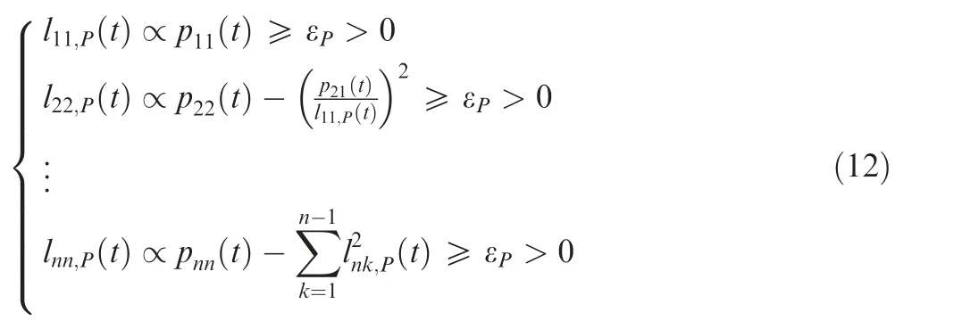
Take into account that the square root, which is normally required to exactly calculate the diagonal entries for the Cholesky factorization using Eq.(12),is left out in this formulation on purpose and only the proportionality (symbolized by ∝)with the radicand is specified and used in the optimization.This is first of all due to the fact that a real,positive radicand ensures the existence of a Cholesky factorization(i.e.,that the analyzed matrix is positive definite)and second of all that the square root generally creates numerically ill-conditioned derivatives close to zero.Furthermore,the initial guess for the optimization variables might not ensure that the radicand is greater than zero and thus,the optimization may abort due to taking the square root of a negative value.Thus,only the radicand is used in the constraint and must be greater than a user-specified, strictly positive threshold ε(once more,this threshold ensures numerical stability and a proper formulation for the nonlinear optimizer), which is a sufficient condition for the purpose of ensuring that the matrix P(t )itself is positive definite.
Overall, Eqs. (11) and (12) provide the basic means to ensure stability of the LTV system inside optimization and are therefore already sufficient to ensure the system’s stability.In addition, robustness related to desired convergence properties of the error based on the Lyapunov function may be ensured by using the convergence bounds specified in Eq. (7). Here, specifically the coefficient cis of interest as it enforces a lower bound on the convergence rate of the error to zero. Thus, the minimal eigenvalue of the Q(t ) should be larger than a user-defined threshold ε(again, the threshold ensures numerical stability and a proper formulation of the nonlinear optimization problem):
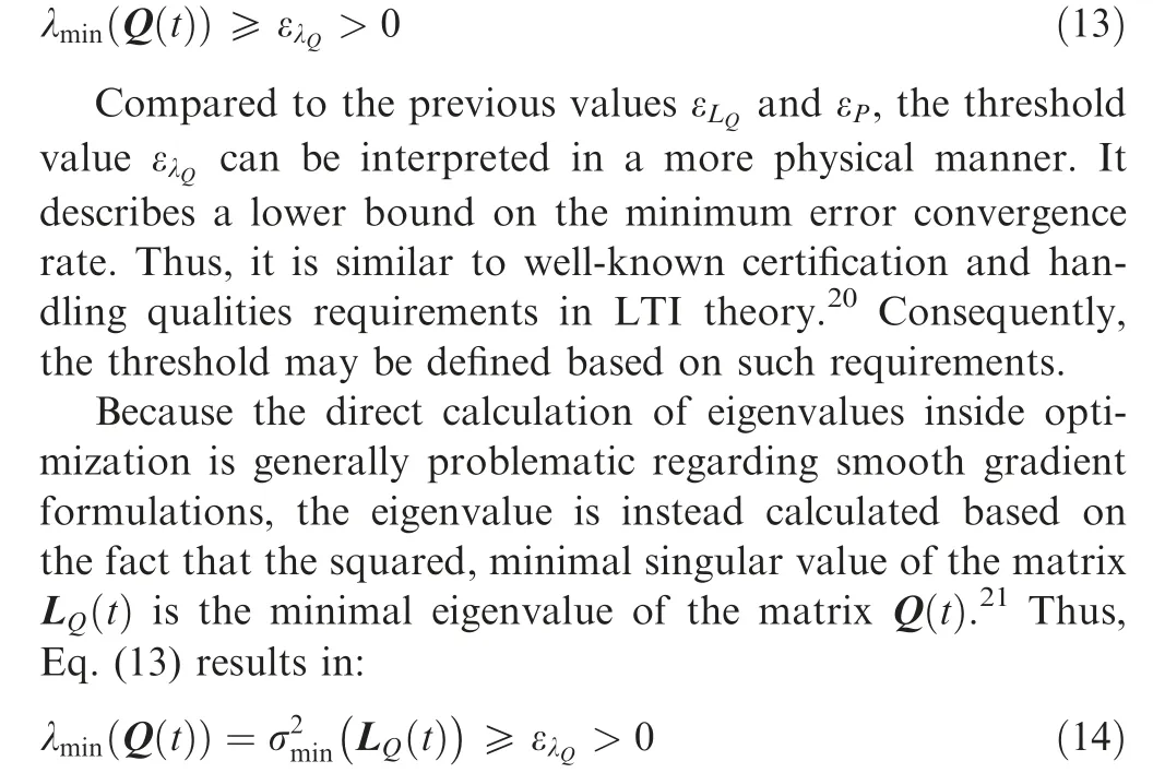
Here, σ(∙) is symbolizing the minimal singular value.
To avoid the calculation of the singular value in gradientbased optimization (due to the same reasons as for the eigenvalue), a method proposed in Ref. [22] is used to bound the minimal singular value based on the determinant, det (∙), and Frobenius norm, ||∙||, of the matrix L(t ):

Consequently, Eq. (15) provides a safe bound that can be easily and numerically efficiently incorporated within the trajectory optimization problem formulation.
Overall,the designed trajectory does therefore not only feature a stable LTV system, which is ensured by applying Eqs.(11) and (12) as constraints in the optimization problem, but also desired convergence, i.e., robustness, properties of the Lyapunov function, and thus the error, by using the methodology in Eq. (15).
4. Application example
This section gives an application examples for the developed optimal control-based design of trajectories accounting for the stability of error dynamics LTV systems. Therefore, the LTV system for a path-following controller,used as the example in this study,are introduced in Section 4.1,while their stabilization by a feedback error controller is described in Section 4.2. Then, the dynamic model used in the trajectory optimization is given in Section 4.3. Following, Section 4.4 shows the statement of the trajectory optimization problem including the stabilization of the LTV error dynamics.Finally,Section 4.5 shows an assessment of the controller’s performance in simulation.
4.1. Linear time-varying trajectory-/path-following error dynamics
In this study, a LTV system for the error dynamics of a nonlinear trajectory deviation controller is used to analyze the proposed trajectory optimization problem formulation accounting for the LTV dynamics stabilization. It is formulated based on Ref. [4]. The considered path-following problem is visualized in Fig.1 with the path deviation state vector defined as follows:
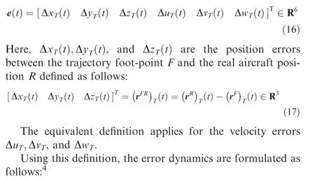
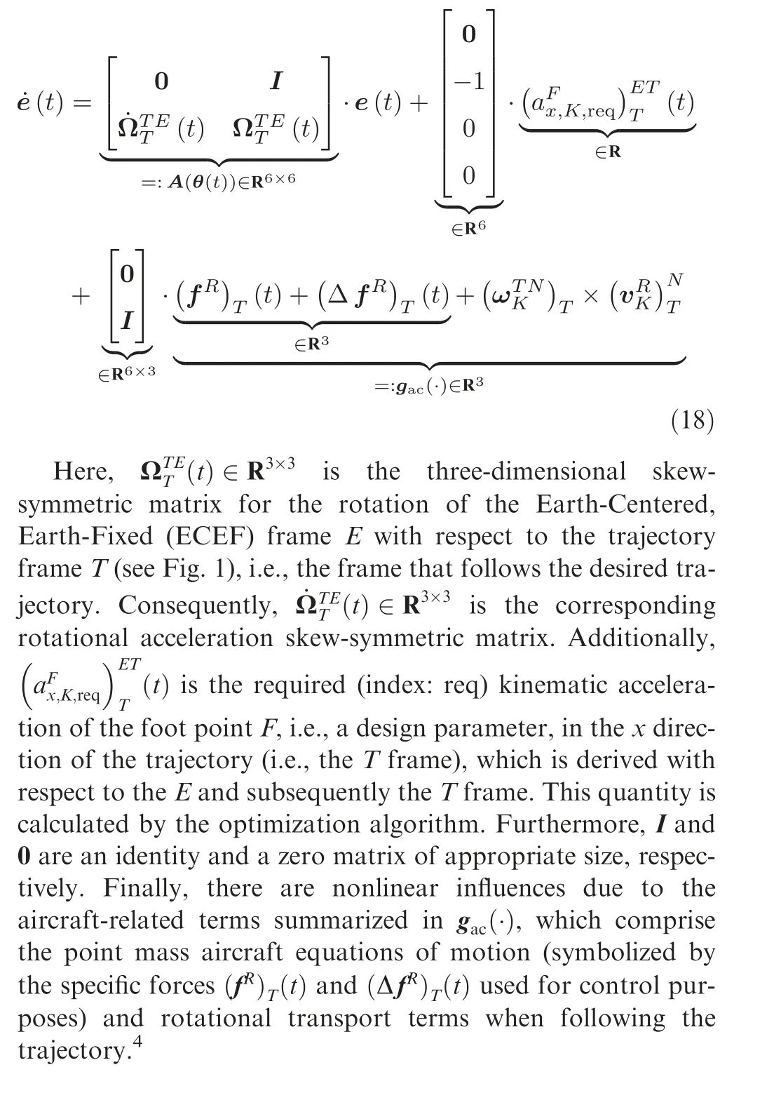
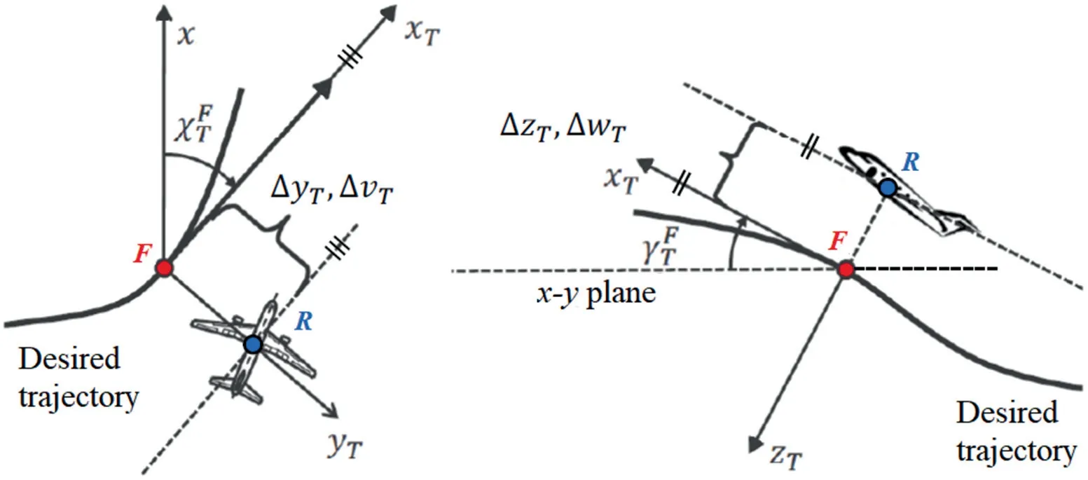
Fig. 1 Visualization of basic idea for nonlinear trajectory/path-following controller based on trajectory reference point F, i.e., the foot point along the desired trajectory, as well as the definition of the path deviations and their derivatives (adapted from Ref. [4]).
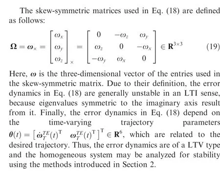
4.2. Stabilizing linear time-varying error dynamics by feedback controller design
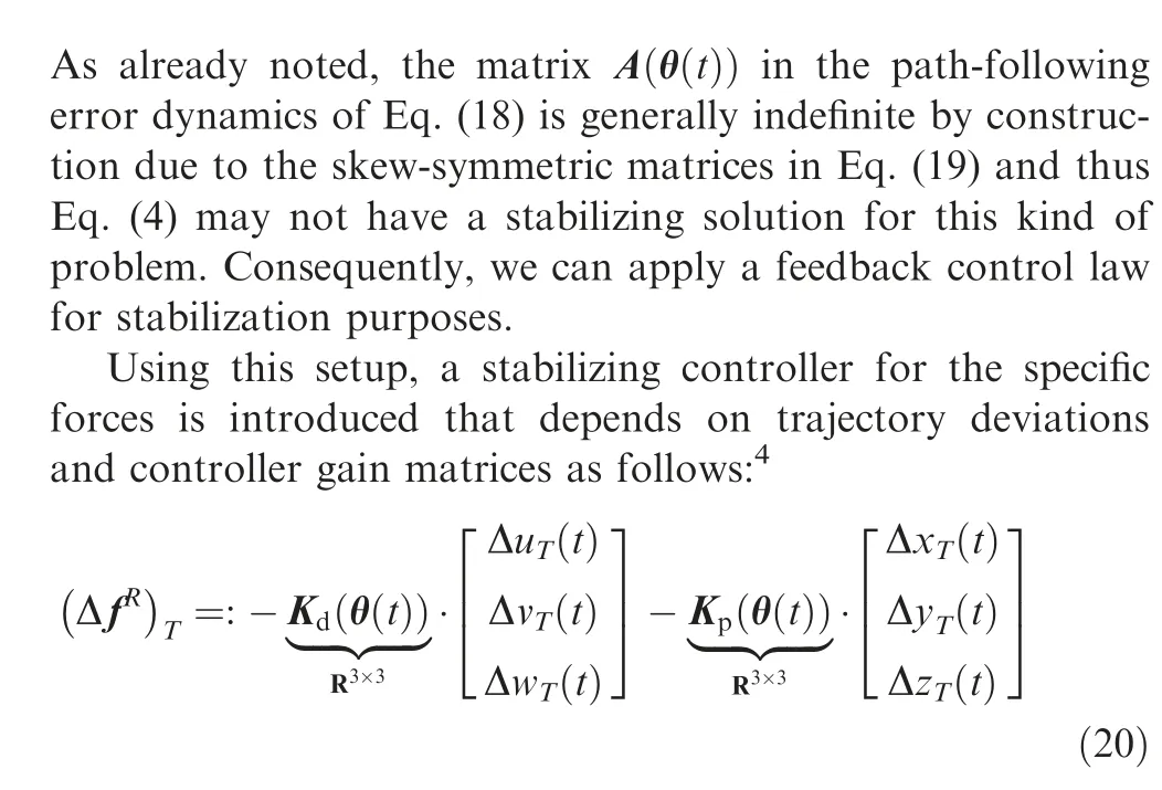
Thus, the feedback path deviation error controller is of a standard proportional-derivative type. Here, the parameterdependent matrices K(θ(t )) and K(θ(t )) are controller gains that are designed to stabilize the dynamic system.
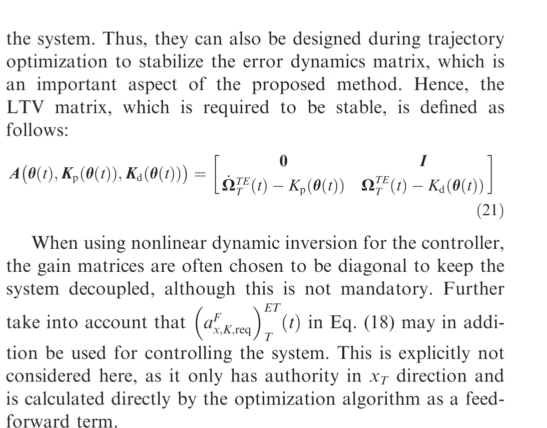
It should be noted that the controller gain matrices in Eq.(20) can generally be chosen freely by the user to stabilize
4.3. Model and trajectory optimization formulation
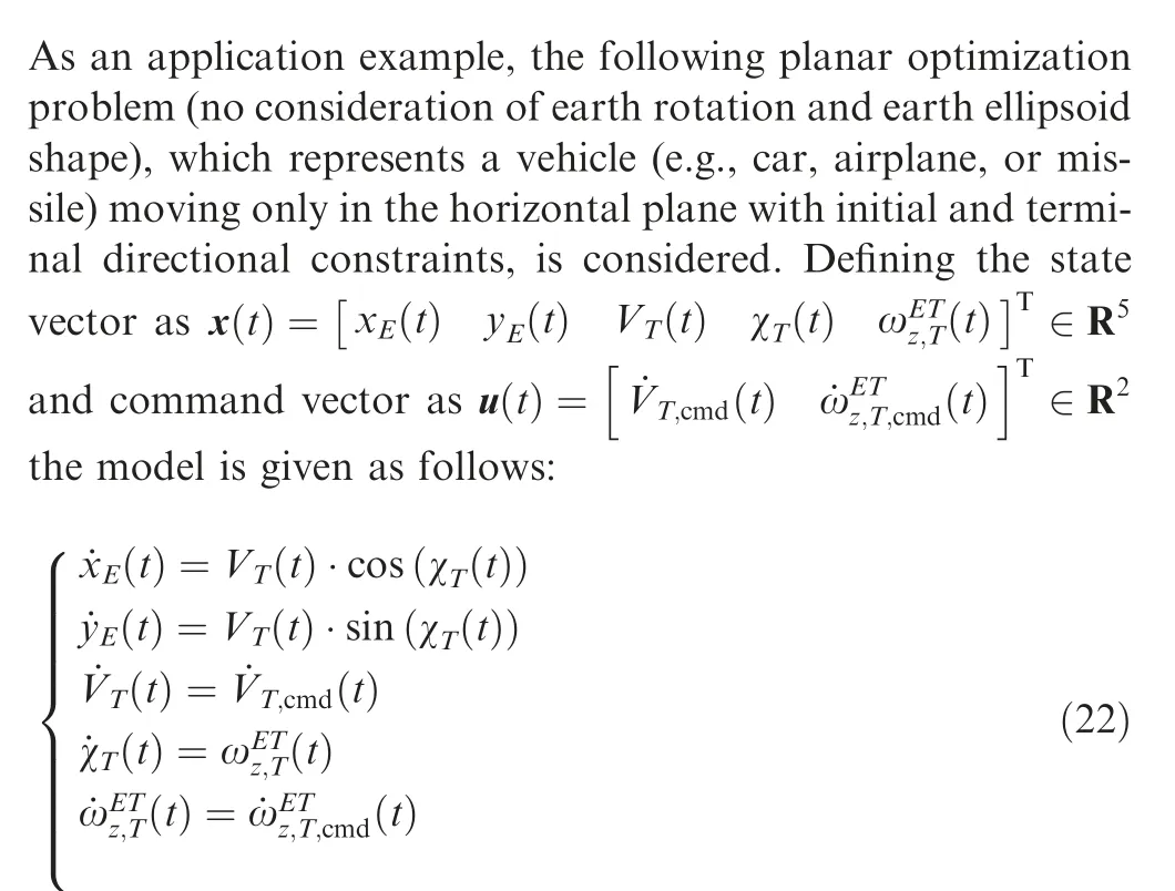
This formulation is often used to model simple trajectories,where the dynamic system should only move in one plane. In aviation, this is often required when following different way-points on a constant flight level.The states and controls in the EoMs are defined and limited as well as scaled for the optimization problem as shown in Table 1.

Table 1 States and controls in optimization problem.
As this model can only move in the horizontal plane and has the yaw motion as a single degree of rotational freedom,the error dynamics of Eq. (18) simplify to:
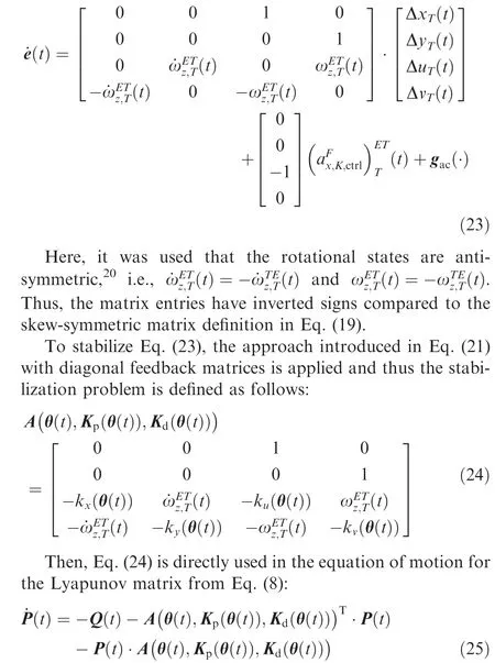
Here, the positive definiteness of the matrices Q(t )≻0 ∊Rand P(t )≻0 ∊Ris ensured as described in Eq. (11) and Eq. (12), respectively. For these inequalities,threshold values of ε=10and ε=10are used respectively to be certain of the positive definiteness of the matrices.Generally, a well-conditioned optimization problem is also created by this choice and optimality is only reduced marginally. In addition, the threshold for the minimal eigenvalue of the matrix Q(t ) in Eq. (15), i.e., the indicator for the minimal convergence rate of the Lyapunov function derivative in Eq.(6),is defined to be ε=0∙1.This has proven to be a good trade-off between convergence properties and optimality,while also considering the conservative nature of the approximation in Eq. (15).
Consequently, the state and control vectors for the planar EoMs in Eq.(22)are augmented by the matrix entries required in the Lyapunov matrix equation of motion as well as the controller gains as follows:
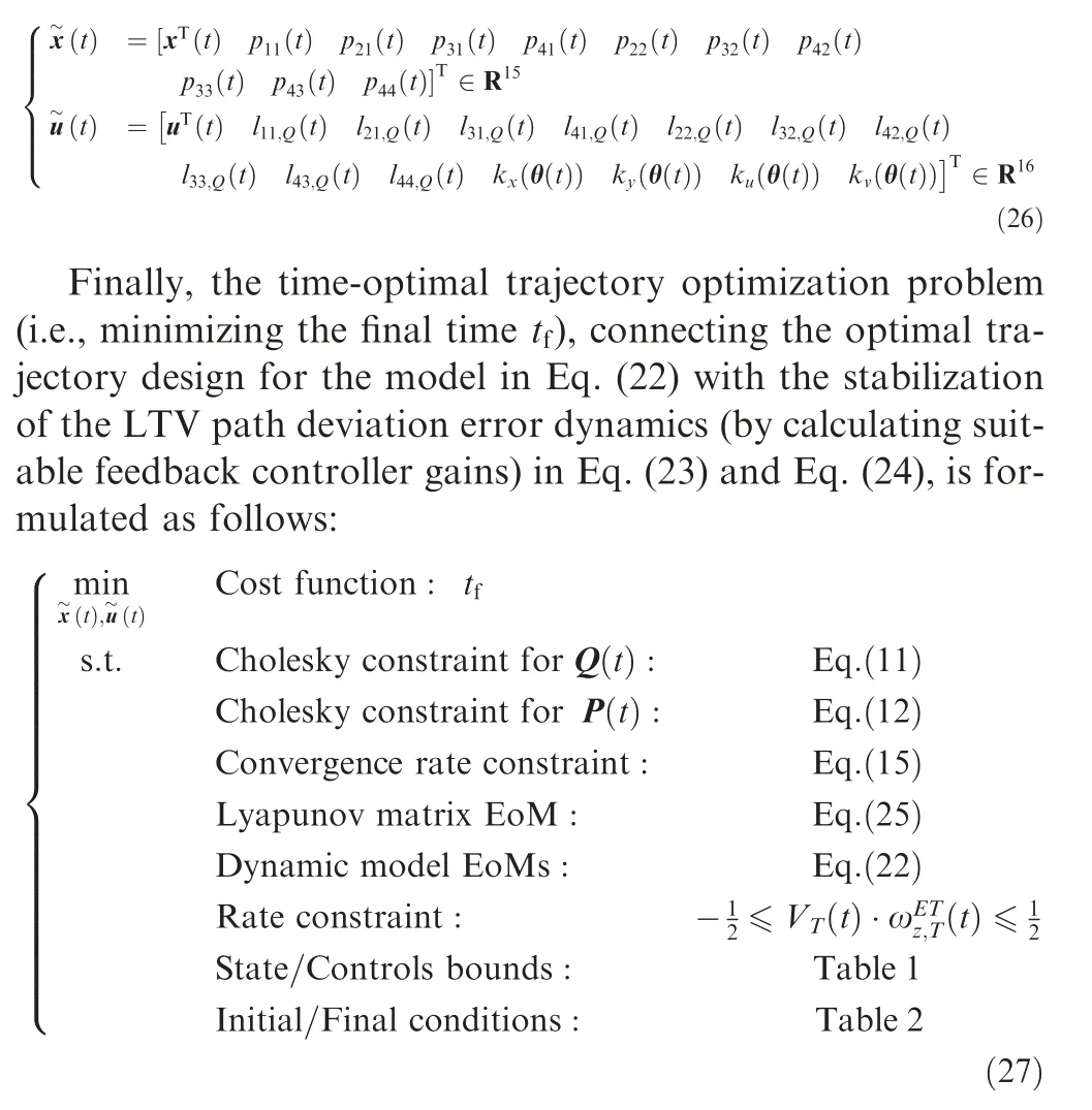
The proposed design procedure is demonstrated through this example. Here, the rate constraint specifies a limitation of the maximal allowable turn acceleration, which is introduced to improve the model’s fidelity. The state/control bounds and the boundary constraints are given in Tables 1 and 2, respectively (unspecified values are assumed to be unbounded). Generally, the aforementioned constraints together with the cost function and the dynamic model EoMs formulate a classic time-optimal nonlinear trajectory optimization problem with state and control constraints.In parallel,the trajectory optimization problem in Eq. (27) designs the feedback gains in an optimal manner for the path controller to stabilize the LTV system of the path deviation error dynamics using the constraints and EoMs based on a time-dependent Lyapunov stability analysis. Conventionally, these two parts are done separately, while the proposed method integratesthem into a single trajectory optimization problem as illustrated in Eq. (27). Therefore, the proposed methodology enables a better tuned optimal design of trajectory and controller for the desired task.

Table 2 Boundary conditions of states and controls in trajectory optimization problem.
The trajectory optimization problem in Eq. (27) is solved using the free-of-charge MATLAB® toolbox FALCON.m,which applies a trapezoidal collocation discretization to solve this continuous trajectory optimization problem in Eq. (27)by means of nonlinear programming. For this purpose, the interior-point optimizerwith linear solver ma97is used. The problem was discretized in time on a linearlyspaced grid with 101 points with optimality and feasibility thresholds of 10. As the initial guess for the states, a linear interpolation between the values at the initial and final boundaries was chosen. The controls were initialized by the mean value of their bounds. Generally, the Cholesky matrix entries were initialized with identity matrices. This setup yielded smooth and reasonably fast convergence without numerical difficulties.
4.4. Optimal control-based trajectory design
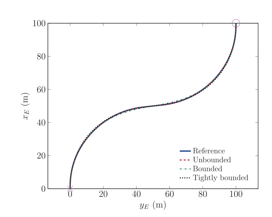
Fig. 2 Comparison of optimal trajectories.
The optimal trajectories, obtained for the reference optimal trajectory without a constraint on the error dynamics stability(‘‘Reference”; solid blue), the results with ‘‘unbounded” gains(i.e.,gains that can be chosen by the optimizer to be very large;‘‘Unbounded”;dashed red),the results with limits on the gains(‘‘Bounded”; dash-dotted green; values defined in Table 2),and the results with more tightly bounded gains (‘‘Tightly bounded”; dotted black; values defined in Table 2) are shown in Fig.2:It is clear that the reference and the unbounded case match very well and are equal from the viewpoint of the numerical tolerances of an optimizer. On the other hand, the results with bounded gains clearly show that the optimal trajectory differs when the gains cannot be chosen large enough by the optimizer to exploit the full physical capabilities of the dynamic model.Contrary to often used approaches in optimization by introducing a Lagrange function penalty(e.g.,for the control effort),achieving these trajectories is automatically given in this setup by the stability constraint. This avoid the cumbersome procedure of appropriately solving the resulting Pareto problem using appropriate scaling factors, but gives a clear and unqiue connection between the reduced optimality and the enforced stability constraints. This consequently means that a less aggressive,less optimal,and smoother trajectory is chosen as the optimal one.This is also clear when looking at the final times obtained from the optimization: For the reference case,we have 31∙8114 s,while the cases with stabilizing the LTV system result in 31∙8114 s,33∙0422 s, and 34∙5679 s for the unbounded, bounded, and tightly bounded case, respectively. Thus, as already discussed, the unbounded case results in the same optimal time, while the other cases result in a relative optimality reduction of 3∙8689%(bounded)and 8∙6650% (tightly bounded), respectively, explaining their smoother, less aggressive trajectory design.
This reduced aggressiveness and increased smoothness is also depicted in Fig. 3 showing the trajectory states. First of all, the turn velocity is reduced, which is one factor for an increased optimal time. Furthermore, the turn angle changes smoother, which is a consequence of the smoother rate command, especially in the beginning, the middle, and the end of the trajectory. Still, the maximal magnitude of the turn rate is similar in all cases, suggesting that, although the stability of the error dynamics must be ensured, the physical capabilities of the vehicle are still reasonably exploited.
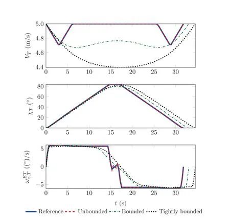
Fig. 3 Comparison of optimal state histories.
Continuing, Figs. 4 and 5 show the optimal gain history and the corresponding eigenvalues of the matrix Q t( ) used in the Lyapunov function candidate derivative in Eq. (3). It can be seen in Fig. 4 that the unbounded case has large feedback gain values, but still does not reach its limits (Table 1), which shows that it can be considered as‘‘unbounded”.The gains are significantly varying over the time interval, which shows that the optimizer tries to find an optimal, fast adapting controller gain for each state in the LTV system it encounters. For the bounded cases the gains are actually significantly smoother and to some extinct almost constant,which suggests a reduced optimality but also smoother operation. This is also specifically seen when looking at the results in Fig.5 showing the real part(Re{∙})of the eigenvalues of the matrix Q(t ),which is an indicator of how fast errors in the dynamics are reduced by the error controller.Here,the unbounded case has stable(negative real part),but very large eigenvalues.This suggests fast reduction of the error in theory,but may not be reasonable in practical applications due to modeling or sensor errors as well as disturbances.On the other hand,the bounded cases also stabilize the system,but with much smaller magnitude.This relates to a more reasonable behavior of the error controller and also its practical applicability. In addition, Fig. 5 shows that the desired constraint on the minimal eigenvalue (displayed in dashed-dotted magenta as labeled as λ(t )) defined in Eq.(15) is always fulfilled even with additional margins. The reason for these safety margins is illustrated in Fig. 6: Here, the approximation(dashed red line)for the minimal singular value of the matrix L(t ) for the three gain cases, which is used in Eq. (15), is compared to the real singular value of the matrix(solid blue line), which is calculated in a post-processing step after the optimization. It is clear that the approximation is indeed a conservative lower bound and thus,the optimal solution does not reach the lower bound as it would be expected for the solution of an optimization problem.Still,an increased conservatism and thus robustness may be desired in multiple applications. Additionally, less conservative approximations for the singular value in Eq. (15) may be used to improve optimality.
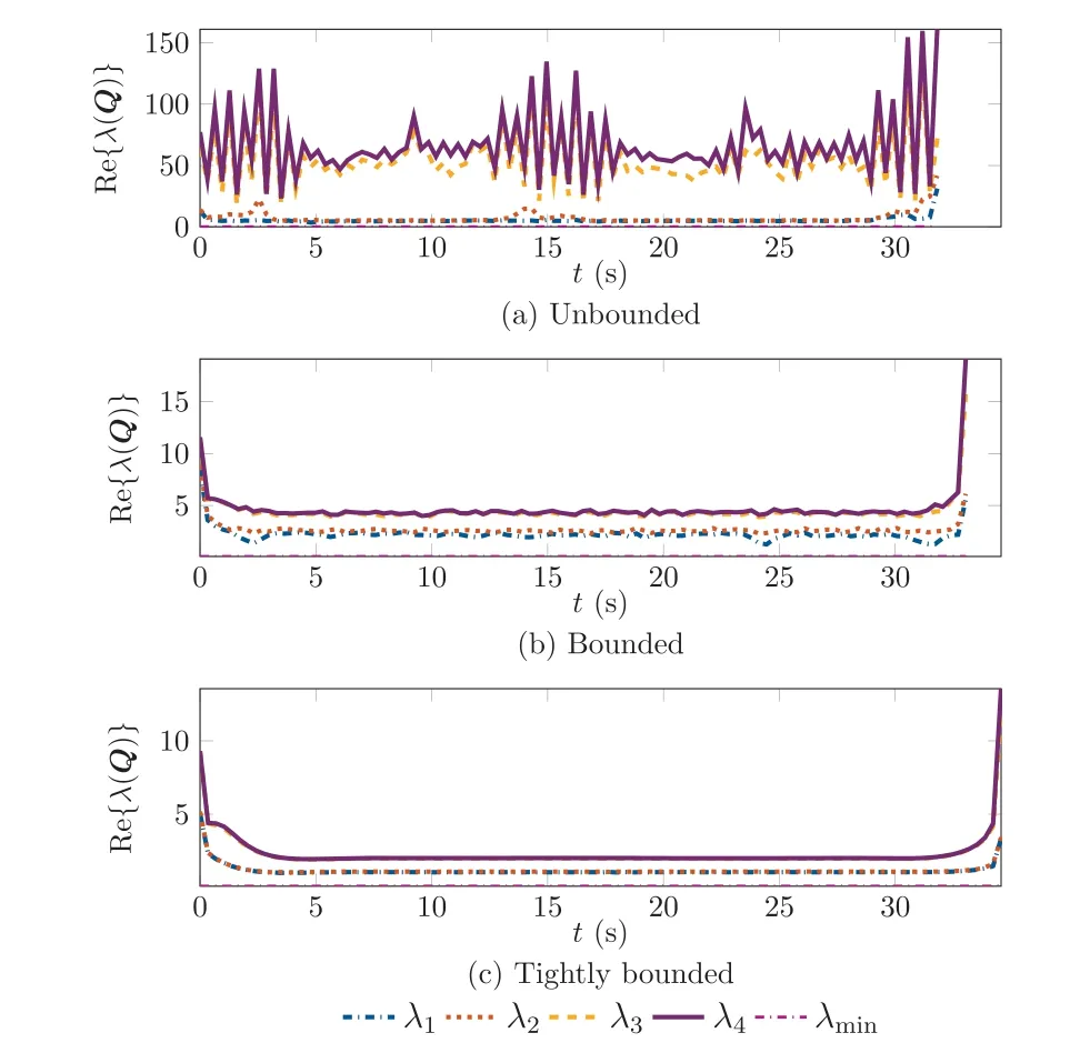
Fig. 5 Comparison of real part of optimal eigenvalue histories for unbounded and bounded cases for the matrix Q(t ) in the Lyapunov function candidate derivative.
Furthermore, Fig.7 depicts the real parts of the eigenvalue histories for the matrix P(t ) used in the definition of the Lyapunov function candidate in Eq.(2).Here,it is first of all clear that the required positive definiteness is ensured as all real parts of the eigenvalues are positive. Furthermore, a similar behavior as in Fig. 5 can be seen, i.e., that by decreasing the gains the eigenvalues become smaller, which results in a feedback controller that is better suited in practice.
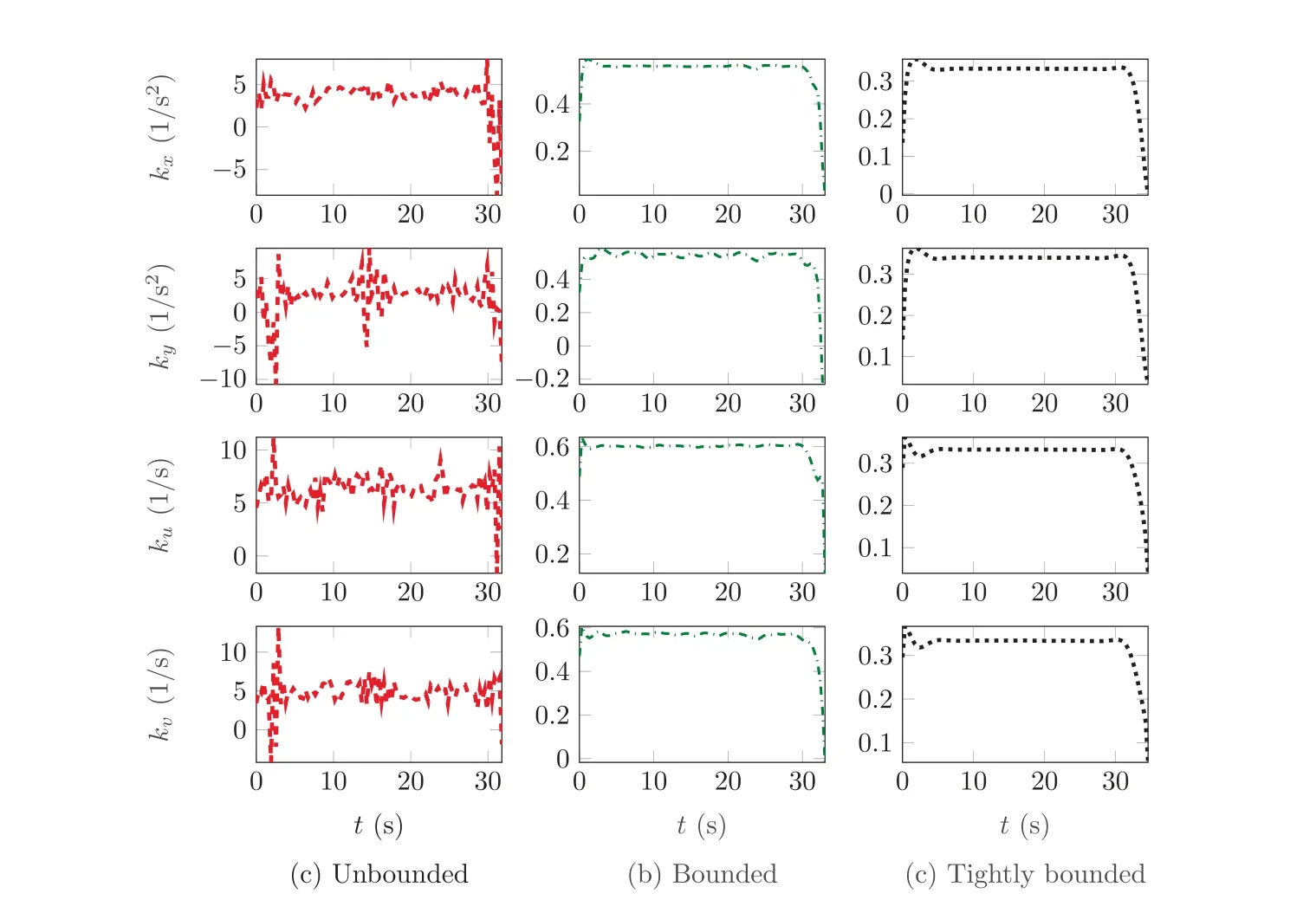
Fig. 4 Comparison of optimal gain histories for unbounded and bounded cases.
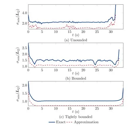
Fig. 6 Comparison of approximation for and exact minimal singular value for unbounded and bounded cases for the matrix LQ (t ) used in the convergence rate constraint for the minimal eigenvalue of the matrix Q(t ).
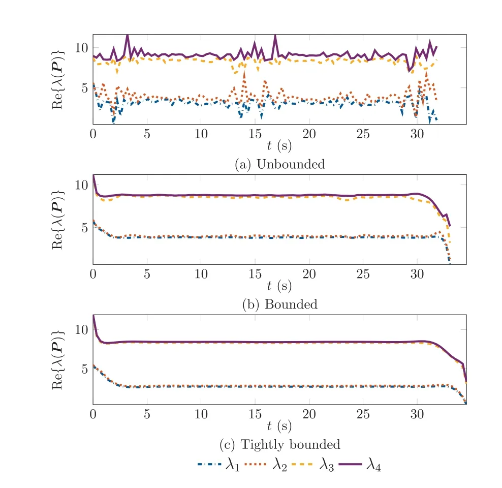
Fig. 7 Comparison of real part of optimal eigenvalue histories for unbounded and bounded cases for the matrix P(t ) in the Lyapunov function candidate.
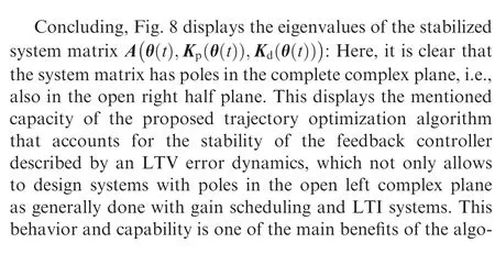
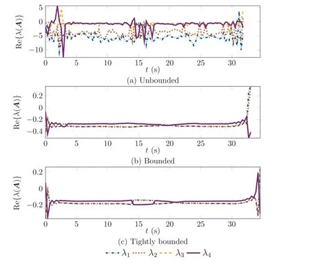
Fig. 8 Comparison of real part of optimal eigenvalue histories for unbounded and bounded cases for the system matrix A θ t( ),Kp (θ(t )),Kd (θ(t )))including the optimal gains.

4.5. Evaluation of controller performance
In this section,a simulation assessment of the controller’s performance is carried out, in which specifically the stability and robustness properties are examined and verified. This is done to validate the theoretical stability characteristics obtained from the optimal control-based design in Section 4.4 within a practical application scenario. Additionally, the resulting feedback gains performance should be assessed. For this purpose, the model’s initial position is offset by 10 m to the left(‘‘west” direction). Therefore, the controller has an initial trajectory deviation that needs to compensate to follow the originally desired path properly.For the controller,the results with the bounded gains is chosen.
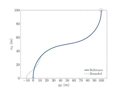
Fig.9 Comparison of planned optimal trajectory and simulated trajectory including initial offset with bounded gains.
At first, Fig. 9 visualizes the planned optimal trajectory(‘‘Planned Trajectory”;solid blue)and the simulated trajectory using the bounded gains (‘‘Bounded Controller”; dashed green) to specify the pseudocontrol within the nonlinear dynamic inversion control law that is derived from the LTV error dynamics.It is clear that the controller achieves the desired task to follow the reference trajectory properly and smoothly. This also shows that the bounded gain case is a trade-off between tracking accuracy and speed. Consequently,different performance criteria can be fulfilled by adapting the bounds on the gains suitably.There is an overshoot when coming close to the trajectory which suggests that the gains may yet be still too aggressive for perfect, smooth convergence.
Continuing, Fig. 10 shows the Lyapunov function and its derivative until a simulation time of 12 s is reached and the error between real and desired trajectory becomes negligible.It is clear that the Lyapunov function is always positive,while its derivative is always negative as required for stability and enforced within the optimization. It is furthermore clear that after around 8 s the error becomes very small between real and desired trajectory and we achieve a good convergence.To visualize this behavior further,Fig.10 contains the theoretical bounds on the decay of the Lyapunov function as well as its derivative as formulated in Ref.[16]and specified in Eq.(5)(denoted by ‘‘c-decay” and ‘‘c-decay”, respectively) and Eq.(6) (denoted by ‘‘c-decay” and ‘‘c-decay”, respectively).These show that the actual decay of the Lyapunov function and its derivative is contained within the theoretically predicted extreme bounds,i.e.,the coefficient bounding the matrix norm multiplied by the norm of the error. In addition, the decay of the Lyapunov function derivative is also always at least given by the bound enforced using the constraint on the minimal eigenvalue (λ-decay; dotted cyan line) in Eq. (15).Thus, the constraint enforced in the optimization also has an influence in the real scenario and accurately predicts a conservative, robust convergence bound as desired. This is a further strong argument on the applicability of the proposed trajectory optimization framework accounting for the LTV stabilization in application scenarios.
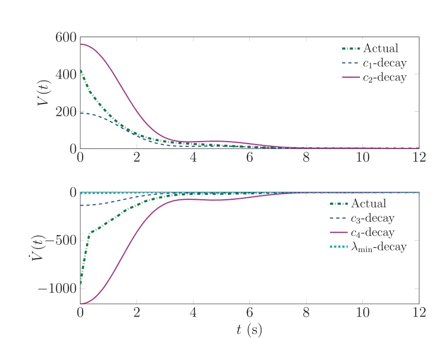
Fig. 10 Development of Lyapunov function and its derivative including theoretical decay bounds when trying to follow the optimal trajectory with an initial offset and bounded gains.
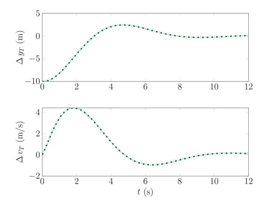
Fig.11 Development of lateral path deviation and its derivative when trying to follow the optimal trajectory with an initial offset and bounded gains.
This behavior is further displayed in Fig. 11, which shows the lateral path deviation and its derivative. As already noted the lateral path deviation is often the most interesting aspect of the trajectory controller as it is most often the most critical.Thus, this figure is displayed here to show the achieved tracking accuracy by the controller even when only small and bounded gains are allowed. As already clearly indicated by the previous figures, there is one overshoot and one small undershoot but after 8s the trajectory tracking is very good especially considering that no additional error integrators are used in the setup.
5. Conclusions
This study introduced the connection of optimal control-based trajectory design with stabilization of Linear Time-Varying(LTV)dynamics,including the design of adequate gains,which showed significant application potential. The novelty of this approach is the connected design of both the trajectory(as part of the feedforward control)and the feedback controller part of a trajectory tracking error dynamics that is described by stabilizing an LTV system. To this end, a trajectory optimization problem was formulated that contained both the standard dynamic model and its constraints as well as the Lyapunov analysis-based constraints accounting for the stability and robustness of the LTV system. These include constraints on the positive definiteness of the involved matrices in the Lyapunov matrix equation of motion that have been numerically efficient and stable incorporated using the idea of the Cholesky factorization. Additionally, constraints on the minimal decay rate of the Lyapunov function derivative, and thus, the error,are enforced to account for robustness and performance requirements. Consequently, this view allows for a coupled optimal trajectory and stable feedback controller design,which ensures stability and efficiency of the designed trajectory in real application, thus facilitating performance and availability.
Concluding, this study has formed a reliable theoretical foundation for the practical application case of designing optimal trajectories considering the stability and robustness of dependent LTV systems in a single framework to exploit the full capacity of the dynamic system. This theoretical foundation enables the exploration of more sophisticated gain design strategies for the LTV dynamics, including system response shaping or robust design considering uncertainties, within the optimization as additional cost or constraints. Furthermore,it also enables handling of objectives dealing with different practical needs, such as a required level of smoothness.Finally, it is extendable to specifically tailored (parameterdependent) Lyapunov functions to increase the optimality and reduce conservatism.
The authors declare that they have no known competing financial interests or personal relationships that could have appeared to influence the work reported in this paper.
This work is supported in part by the TUM University Foundation Fellowship and in part by the German Federal Ministry for Economic Affairs and Energy (BMWi) within the Federal Aeronautical Research Program LuFo V-3 through Project‘‘HOTRUN” (No. 20E1720A).
 Chinese Journal of Aeronautics2022年7期
- Chinese Journal of Aeronautics的其它文章
- An online data driven actor-critic-disturbance guidance law for missile-target interception with input constraints
- Study on excitation force characteristics in a coupled shaker-structure system considering structure modes coupling
- Smooth free-cycle dynamic soaring in unspecified shear wind via quadratic programming
- Active and passive compliant force control of ultrasonic surface rolling process on a curved surface
- High dynamic output feedback robust control of hydraulic flight motion simulator using a novel cascaded extended state observer
- Composite impact vector control based on Apollo descent guidance
