Active and passive compliant force control of ultrasonic surface rolling process on a curved surface
Kaiming ZHANG, Ji WANG, Yixin LIU, Shuang LIU, Xiancheng ZHANG
School of Mechanical and Power Engineering, East China University of Science and Technology, Shanghai 200237, China
KEYWORDS Active and passive compliant;Curved surface;Force control;Surface integrity;Ultrasonic surface rolling process
Abstract Ultrasonic surface rolling process (USRP) is one of the effective mechanical surface enhancement techniques.During the USRP,unstable static force will easily do harm to the surface quality.In order to achieve a higher surface quality on the part with a curved surface,an active and passive compliant USRP system has been developed. The compliant USRP tool can produce the natural obedience deformation along the part surface. Force control based on the fuzzy Proportional-integral-derivative (PID) method is then designed to maintain the static force during the USRP.Experiments have been performed on a real aero-engine blade with curved surface.It is proved that the deigned active and passive compliant USRP system can significantly reduce the force variation from 42.2 N to 4.2 N, and achieve a uniform surface quality after processing.
1. Introduction
Curved surface is one of the typical structures used in the manufacturing industry,such as aero-engine blades or blisks.In general, the surface quality of curved surface directly determines the service life and performance of the whole part. However, due to the complex structure of curved parts, it is difficult to guarantee a uniform quality on the surface.In addition,severe loads and poor working conditions will cause some corrosion and cracks during their service time. Therefore, it is of great significance to enhance the surface quality of the curved parts in a bid to ensure its performance and get more financial benefits.
Laser shot peening (LSP), shot peening (SP), deep rolling(DR),etc.are commonly used mechanical surface enhancement (MSE) techniques to enhance the mechanical properties of the parts. After the MSE treatment, a compressive residual stress field will be generated on the surfaces. Thus, the initiation and propagation of cracks are delayed and the service life of parts is extended.Ultrasonic surface rolling process(USRP)is considered as one of the effective surface enhancement techniques in manufacturing. Compared with the MSE techniques mentioned above, USRP does not need a complicated hydraulic system or expensive laser generator, along with low maintenance costs as well as high surface quality.Additionally, during USRP, a rotatable ball (tungsten carbide) is used as a processing tip,which can be attached on the surfaces of parts. Under the combined action of ultrasonic vibration and static force, plastic deformation and large elasticity are generated by the direct contact between the ball and the part surface.As a result,the surface integrity and fatigue properties are remarkably improved. Driven by the advantages of USRP, more and more curved parts are expected to be processed by this powerful technique, such as aero-engine blades,blisks,etc.However,due to the complex surface structure,the variations of processing parameters during the ultrasonic surface rolling process greatly limit the final qualities of parts. In this connection, the processing parameters need to be reasonably controlled as a way to ensure a uniform USRP effect.Static force is one of the important processing parameters during the USRP.Based on the same type of the processing tip with a certain size,path strategy and material properties,the USRP effects on curved surfaces can be controlled by the static force indirectly.
In order to obtain high-quality curved surfaces, the static force should be controlled precisely. Generally, force control is usually divided into active or passive compliance control.In passive compliance control, the tool can generate a natural obedience deformation according to the contact force.Generally,damping,springs,etc.are commonly used as compliant components for absorbing or storing energy.In order to maintain the contact force during the polishing, a compliance tool holder was presented.Compared with the tool without compliant components,the variations of contact force and the surface roughness were significantly reduced. A compliant polishing tool was designed based on an elastic sponge disk in. Also, it is validated that the proposed polishing tool can maintain high global uniformity and obtain a mirror effect surface on curved surfaces.In addition,a tool holder made by the metallic damping alloy was investigated in.Both surface roughness and machining vibration could be guaranteed during the end milling. As mentioned above, the passive compliance control relies on the sophisticated design of hardware.In addition, since there is no force feedback control during the processing, the force is unstable.
Active compliance control exhibits more accurate and flexible than passive compliance control. A closed loop is employed to regulate the force between the tool tip and part surface according to the force sensor.Generally,active force control studies can be roughly divided into two types: traditional and modern intelligent control algorithms.With a spurt of progress in information and computer technologies, traditional force control has been widely used in the manufacturing industry. Active force control was implemented into the polishing of blisks with thin-walled structure. The force variation reduced from 8 N to 1 N by a PI force controller. As such, a higher-quality surface will be delivered. An adaptive controller was applied to the force tracking control of the pressurized tool. During the machining, the active pneumatic compliant tool could be used for the force tracking by selftuning.Due to the easier estimate and control process,modern intelligent force control is gradually applied to the field of polishing, milling, etc. In order to obtain a desired force and expected effect in the uncertain robot-external machining environment, an adaptive variable impedance control method was designed to adjust the machining parameters based on the tracking error in real time. A dynamic threshold-based fuzzy adaptive control method was proposed to avoid the clogging and overload of the polishing wheel. During the polishing,parameters were online-adjusted by fuzzy control rules, and tool marks could be effectively avoided on the part surface.
It is observed that existing USRP applications mainly focus on the cylindrical or the plate specimens. Generally, USRP tool is assembled on the lathe or CNC machine tool and the tool path can be easily offset from the part surface. However,few researches are found that USRP is directly applied to the parts with free-form surfaces, such as the aero-engine blade.Since the processing tip made by tungsten carbide is highly rigid, the static force should be strictly controlled to secure a better surface quality. In addition, the designed paths based on the off-line programming cannot be used directly due to the shape error caused by manufacturing and installation.Aiming at the automatic USRP on the parts with curved surfaces, firstly, an active–passive compliant USRP tool is presented to generate the natural obedience deformation along the machined surface.Then,the fuzzy-PID force control algorithm is adopted to monitor and adjust the static force.Finally, experiments relating to a real aero-engine blade are conducted to validate the effectiveness of the proposed tool and force control method.
The remainder of this paper is organized as follows:section 2 shows the active–passive compliant USRP system. A ring force sensor is assembled in the USRP tool and the spring is used as a compliant component. Further, the force control strategy based on fuzzy PID is proposed in section 3. Finally,experiments on a real aero-engine blade are performed on a self-developed machine tool. Results show that the surface quality of machined areas are promoted successfully.
2. USRP based surface manufacturing system
2.1. Conventional USRP device
As shown in Fig. 1, the conventional USRP device is composed of ultrasonic generator, piezoelectric transducer, amplitude changing rod and tool tip. The ultrasonic generator is used to generate the alternating current of 20 kHz.Meanwhile,the piezoelectric transducer can convert the electrical signals to mechanical vibration at a same frequency.In order to amplify the ultrasonic vibration amplitude,an amplitude changing rod is connected with the transducer.The ball in the processing tip can be rotated to change sliding friction to rolling friction.Thus,the processing tip can impact the part surface with ultrasonic mechanical vibration and rolling motion simultaneously.The total force is the sum of static force and dynamic force.Due to thousands of impacts per second in a small area, the total plastic deformation is determined by the maximum force.The pressure exerted on the part surface is reduced by ultrasonic vibration to achieve the required plastic deformation.Therefore, USRP is particularly beneficial to the treatment of thin section components, such as blades and disks. Generally, the USRP tool is fastened on the industrial robots or CNC machines. Driven by these manipulators, the combined action of static force and ultrasonic vibration generated by USRP tool can refine the grains in the surface layer. In addition, both the hardness and surface roughness are improved significantly.
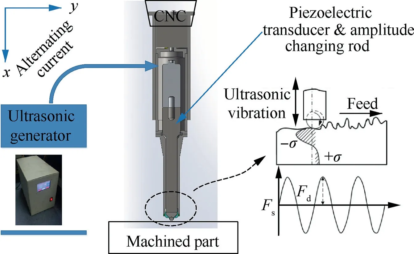
Fig. 1 Conventional USRP device.
The surface integrity after USRP mainly depends on factors including the material properties and USRP parameters. The USRP parameters contain the size of rolling ball, tool’s velocity, step-over distance and some other parameters related to the industrial robots or CNC machines. In addition, the total force of USRP exert a crucial and direct influence on surface quality. The total force Fduring the USRP is the sum of dynamic force and static pressure, it can be expressed as
F=F+F(1)
where Fdynamic force with regularly varying sinusoidal functions is generated by ultrasonic vibration.The static force Fis driven by the CNC or some other machines.Under the combination of dynamic and static force, plastic and sever elastic deformation are generated on the surface layer.Since the ultrasonic vibration amplitude is controlled by the ultrasonic generator during the processing,the USRP effects can be controlled by static force indirectly under the certain conditions of material properties,size of ball,ultrasonic vibration amplitude,etc.
2.2. Automatic USRP system
Manufacturing errors and force-induced deformations of parts with curved surfaces are very common in the industry. The Conventional USRP of the curved parts using the theoretical path will lead to insufficient or excessive USRP effects on the surface. As a consequence, a USPR tool that can adapt the curved surface will obtain a more uniform surface quality.In order to achieve the adaptive USRP on the curved surface,an automatic USRP system is designed on the basis of the active and passive compliant control model, as shown in Fig. 2. In this automatic system, static force control of the USRP tool is realized by the active force control and a compliant USRP tool. The natural obedience deformation along the shape of curved surface will be generated through the USRP tool with flexible design. The USRP system mainly consists of the compliant USRP tool, CNC machine tool/industrial robot, force sensor, and industrial personal computer (IPC).The force sensor can collect the real-time static force and feedback to the computer. The adjustment and compensation of the USRP tool’s position and posture are designed to maintain the constant static force through the control strategy.
2.3. Compliant USRP tool
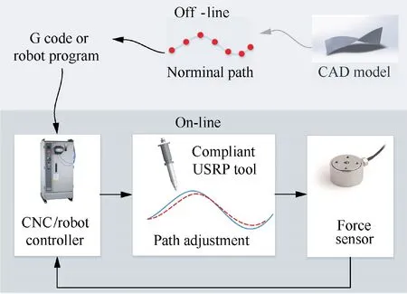
Fig. 2 Automatic USRP system.
An accurate control of static force in the dynamic process is the key to maintaining the uniformity of USRP effects. In order to overcome the difficulty of controlling the static force on curved surface during the USRP,a novel compliant USRP tool is proposed, as shown in Fig. 3. Compared with the conventional USRP tool, spring and force sensor are adopted as the core parts.The spring is added as a compliant component.As a result, the tool can generate the natural obedience deformation along the machined surface. In addition, a ring-type force sensor is installed between the spring connector and the bottom of the tool. The force sensor measures the static force acted on the USRP tool in real time, and the force data is transmitted to the industrial personal computer.Differences between the desired static force and the actual values are compared,and then the modification values of the USRP tool position are calculated. Furthermore, the modification values are transmitted to the robot/machine tool controller,which drives the manipulator to adjust the USRP tool position to maintain a constant static force. The hardware structure is designed to keep the force constant by adjusting the position of USRP tool in response to the real-time change of the part surface.
3. Force control strategy of USRP on curved surface
3.1. Contact analysis
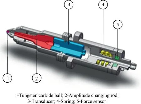
Fig. 3 Compliant USRP tool.
Under the combination of the rolling and high-frequency dynamic vibration, plastic deformation induced by the processing tip will occur on the curved surface. Refined surface grain layer can be generated as a result of the plastic deformation. Nonuniform USRP effects on the part surface will do harm to the surface quality. Therefore, the parameters of USRP should remain constant or quantitatively controllable.In order to simplify the analysis, the plastic deformation can be regarded as a series of circular indentations with center fixed on the USRP path and the contact area can be shown in Figs. 4 and 5.
During the USRP,the directions of total force are the same as the normal ones of part surface at every contact point and change along the designed paths. Apparently, the size of the contact area and depth of indentation are closely related to the total force during the USRP. Since the curvature of the curved surface is much smaller than that of the ball, the contact area of one impact is simplified as a circular indentation.As shown in Fig. 4, the pressure distribution q(x) is closely related to the size of indentation. Therefore, q(x) can be denoted as:
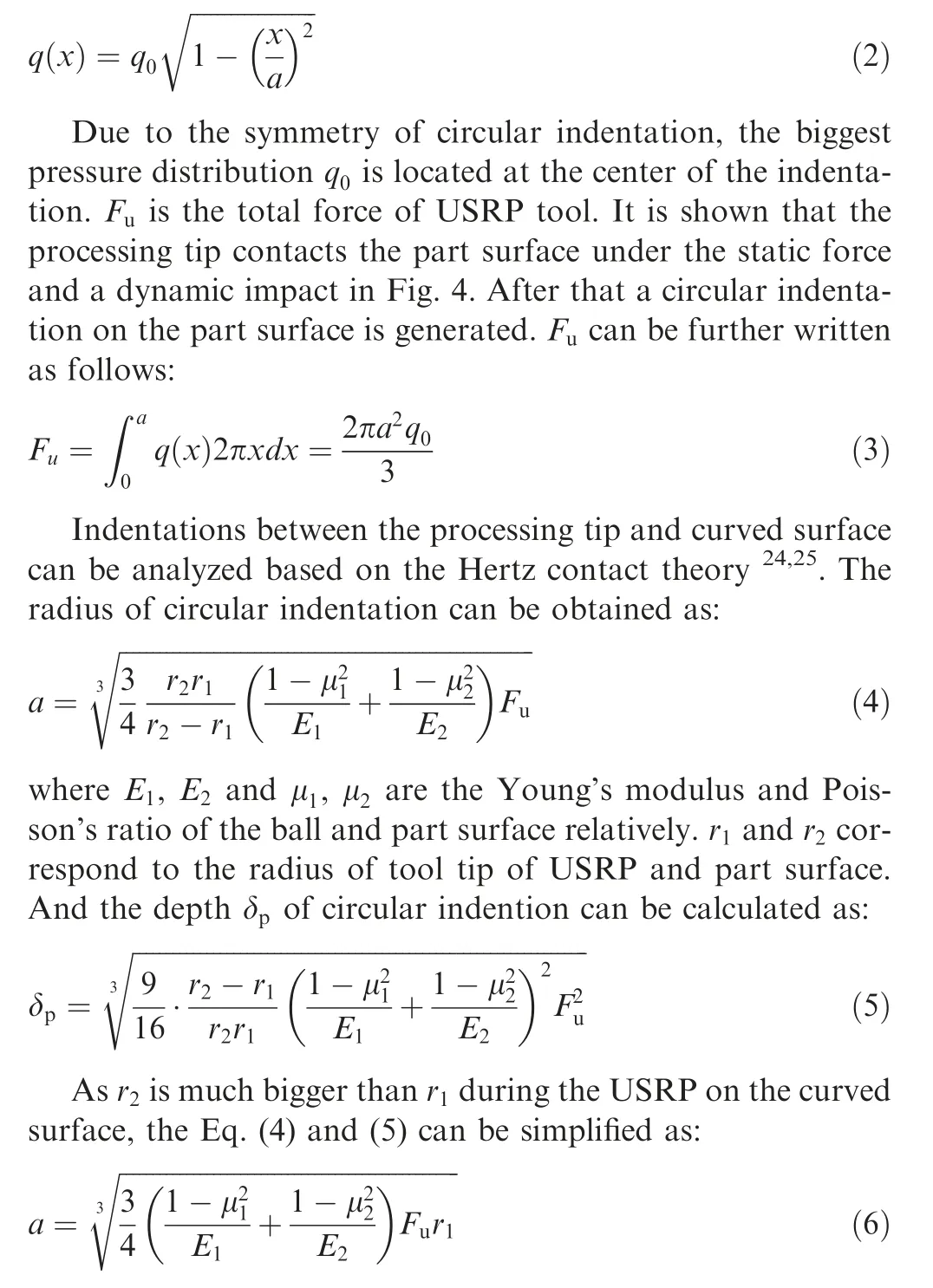
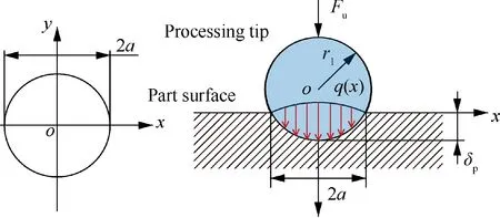
Fig. 4 Plastic indentation after USRP.
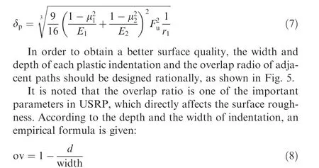
where d is the distance of adjacent paths’ centers, ov is the overlap radio. Obviously, the width and depth of indentation are closely related to the force acted on the part surface. In USRP, dynamic force with regularly varying sinusoidal functions is generated by ultrasonic vibration with high frequency,that is, the dynamic force always keeps a certain type during the processing. Therefore, the surface quality can be adjusted by the static force indirectly under a rational overlap radio.
3.2. Force control strategy based on fuzzy PID
The static force acted on the USRP tip plays an important role in the plastic deformation on the part surface, and the stability of static force affects the accuracy and quality of the part surfaces directly. In order to maintain uniform USRP effects during the process, the system can not only implement the real-time force control strategy on the curved surface, but also avoid the force change caused by machining instability.
Proportional-integral-derivative (PID) controller is commonly used in the manufacturing industry owing to strong robustness, simple structure and easy implementation. However, USRP on the curved part is a very complex process and the dynamic process may cause the unstable deviations between the desired and actual force. Regular PID control with fixed PID coefficients is hard to obtain the accurate and fast dynamic-responses. Eventually, the unstable force will lead to the poor control of surface quality. Compared with the regular PID method, fuzzy PID can adjust the PID coefficients by using the fuzzy rules to realize the active force control in the complex environment. Fig. 6 shows the force control strategy based on fuzzy PID.An explicit force control method is designed based on the position for the controller.During the USRP, force controller outputs a position adjustment according to the force deviation between the desired and actual force.Then the position adjustment is used as a correction to control the position for the force control.In order to maintain the contact force as a constant value,the active and passive compliant control structure is designed based on force feedback and a compliant USRP tool. The USRP tool with the spring improves passive compliance and an appropriate force control strategy is adopted to the active compliance control.
Fig. 6 shows the block diagram of the fuzzy PID control system. The input of original positions is designed from the off-line path planning. The actual position of the USRP tool is:w

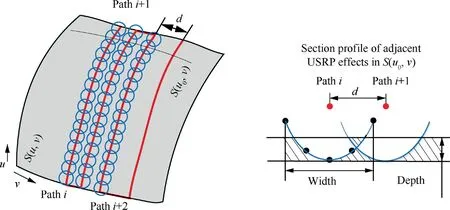
Fig. 5 USRP areas.
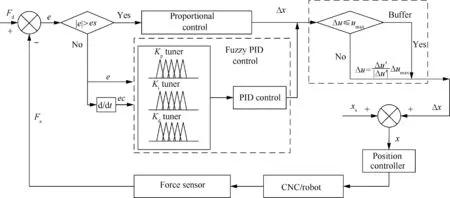
Fig. 6 Fuzzy PID control of USRP.
here xis the original positions of the USRP tool from offline programming. Δx is the tool’s displacement adjusted by the force control. The formula of conventional PID method is as follows:
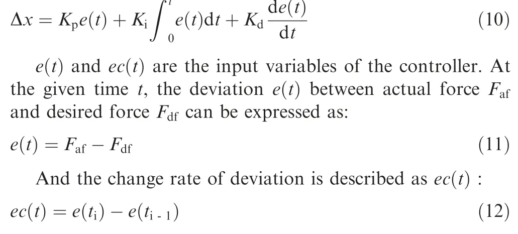
In the conventional PID, K, Kand Kare the constant coefficients, and the performance of PID controller depends on the proper coordination of these three coefficients. In the fuzzy control,K,Kand Kshould be adjusted online according to the fuzzy tuners.The whole fuzzy controller is separated into three sections.According to the fuzzy control strategy,P,I and D tuners are described as:

where n is the P, I and D, respectively; Kis the given initial value of K, Kand K; ΔKrepresents the allowable deviation of K. Generally, Kand ΔKcan be determined from experiments. Therefore, substituting Eq. (13) into (10), the position adjustments of USRP tool can be obtained,as defined by Eq. (14). When the force deviation is quite large, a larger proportional coefficient will give a faster responding speed to reduce the deviation quickly. The fuzzy PID controller is used to eliminate the deviation within required maximum force deviation ewith a higher adaptability.

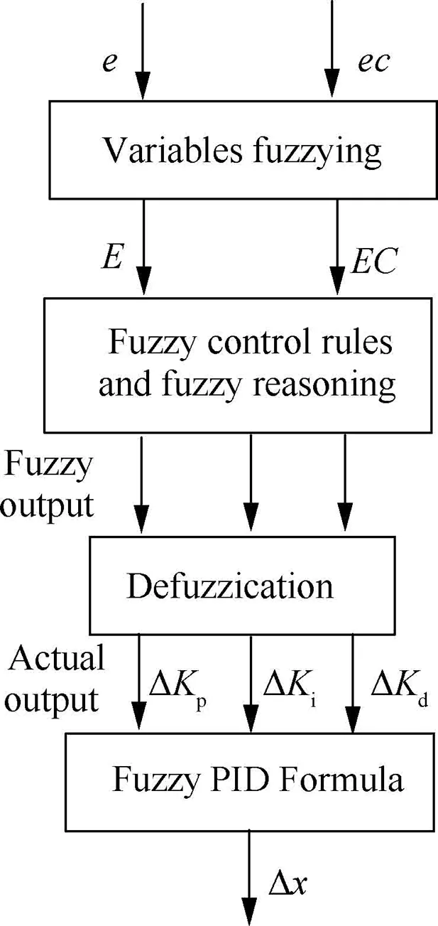
Fig. 7 Flow chart of fuzzy control.
Fuzzy control consists of fuzzy variables, fuzzy set and fuzzy reasoning. The flow chart of fuzzy control is shown in Fig.7.At first,two input variables e(t),ec(t)and three output variables ΔK, ΔKand ΔKare transformed to the input or output fuzzy domains. The fuzzy domains are set as [-3, 3].Then these variables are fuzzified by the triangle membership function. E and EC are the fuzzy variables of e(t) and ec(t) ;The fuzzy set of these five variables is defined as {‘‘PB”,‘‘PM”, ‘‘PS”, ‘‘ZO”, ‘‘NS”, ‘‘NM”, ‘‘NB”}. ‘‘PB”, ‘‘PM”,‘‘PS”,‘‘ZO”,‘‘NS”,‘‘NM”,‘‘NB”are‘‘positive big”,‘‘positive medium”, ‘‘positive small”, ‘‘zero”, ‘‘negative small”, ‘‘negative medium”, ‘‘negative big”, respectively. Then, rules of the fuzzy control are designed in Table 1.By calculating the input fuzzy sets and the designed fuzzy rules, the output fuzzy reasoning results are obtained. Thirdly, ‘‘centroid defuzzication”is used to compute the control outputs of deltas. Finally, the outputs are transformed from fuzzy domain to the output domain.
Since the tool contacts the machined surface directly during the USRP, the force may change with the surface shape sensitively.In order to prevent the force change caused by machining instability and excessive adjustments of the tool,a‘‘buffer”element is designed to restrict the maximum adjustment of USRP tool:

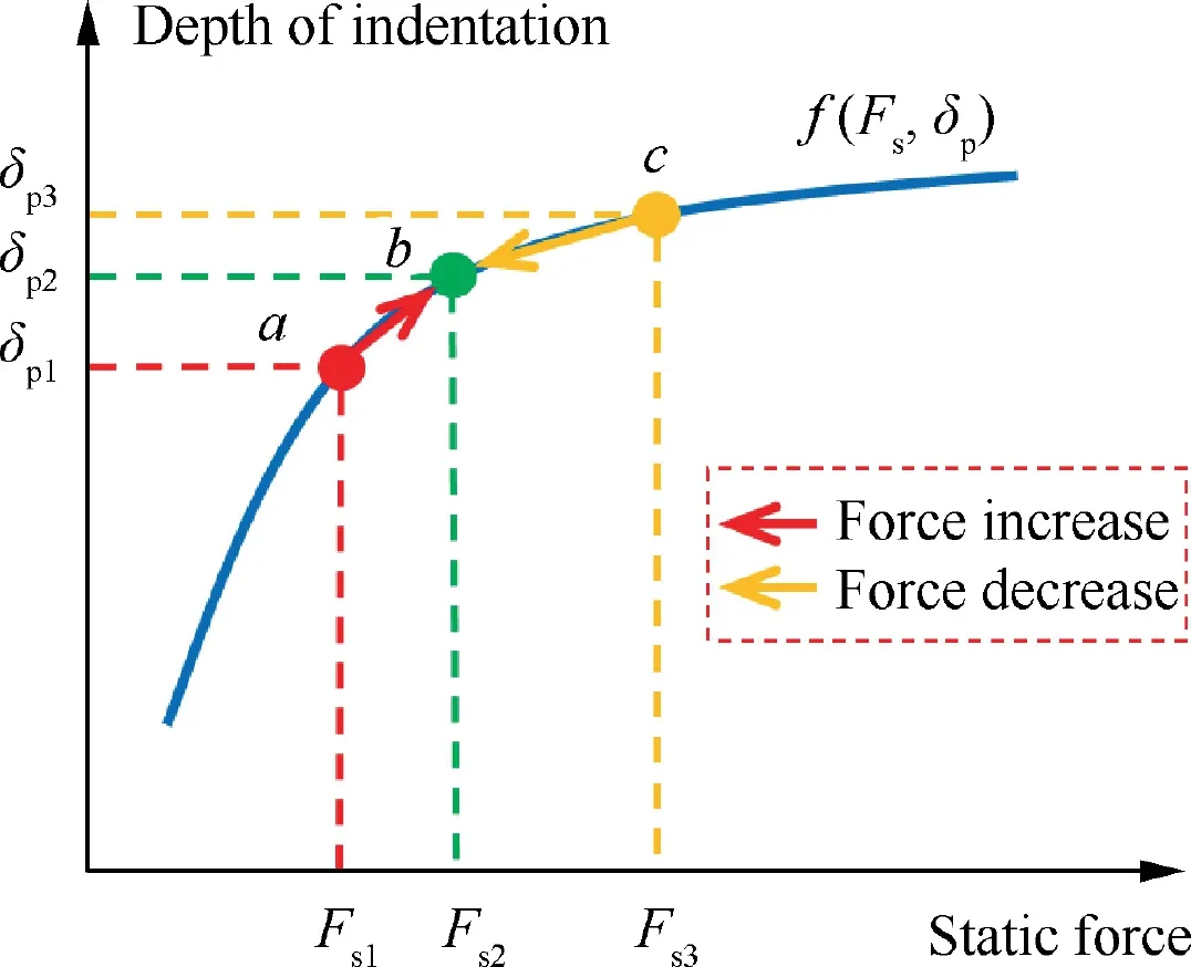
Fig. 8 Force control of USRP.
3.3. Force control process during USRP
According to the proposed fuzzy-PID control strategy, the force reaches to the required value in order to obtain a better surface quality.Intuitively,the width and depth of indentation can be remained as constant values when the static force is fixed. As mentioned above, the surface quality after USRP is closely related to the static force. Fig. 8 shows the adjustment of static force. Curve f(F,δ) is the relationship between the static force and depth of indentation. Note that a, b and c reflect the situations of less-USRP, desired-USRP and over-USRP. When the static force is For F, the corresponding depth of indentation is δor δ, the static force should be increased or decreased to the desired static force F. Since a force control method based on fuzzy PID is applied to maintain the desired static force during the USRP, therefore, the uniform surface quality is guaranteed after USRP.
USRP tool is always assembled in the robot or CNC machine tool. Equipment often operate in a point to point motion,that is,the planned path by off-line programming consists of a series of points in{p},as shown in Fig.9(a).In addition, the tool’s direction at each point {p} is also designed in{d}. Therefore, the tools’ position can be amended at each movement to maintain the constant static force. The USRP tool moves along the planned path {p}from p, p, p, and p, the tool’s direction at each point is designed to coincide with the normal vector of path. Meanwhile, the force control is turned on and the amended path is generated online, as shown in Fig. 9 (b). Therefore, the static force along the normal vector is kept constant and stable by the force control strategy.

Table 1 Fuzzy Rules.
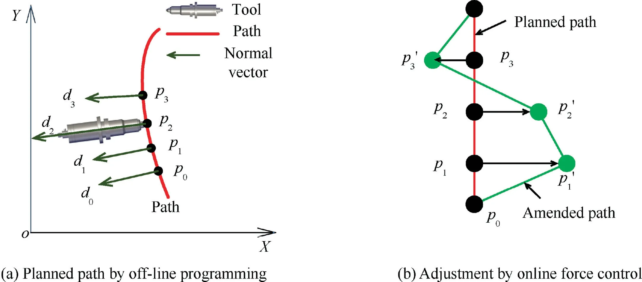
Fig. 9 Online force control based on off-line programming.
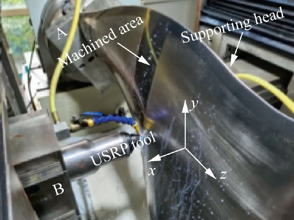
Fig. 10 USRP machine tool.
4. Experiments
Fig. 10 illustrates the experimental setup. The platform consists of a self-developed machine tool, an active and passive compliant USRP tool, and a supporting head. The force measurements are conducted using a ring force sensor (GNSHS03) with a measurement range of 0–1000 N. The force sensor is assembled in the USRP tool as mentioned in Fig. 3.Unmachined part is fixed on the worktable A via a specific chunk, so that it can obtain the rotational and translational movements along Z axis. The USRP tool is assembled on the worktables B, so that it can move on X-Y plane. Since a supporting head is added at the opposite side of the machined area, the possible deformation of the blade is avoided.
In order to test the proposed active and pass compliant control method of USRP,two sets of experiments are designed on a self-designed USRP machine tool shown in Fig. 10. At first,the indentations after USRP by using different static forces are measured. Then, the USRP is performed on a curved part.
4.1. Indentation test of different static forces
The first set of the validation experiments focuses on the USRP effects under the different static forces. The material of experimental parts is TC4 titanium alloy.Static force is considered as independent variables,and the machined part is performed at F=100,200,300 N.Some other USRP parameters are as follows: velocity of USRP tool along the path:v = 4 mm/s, frequency of ultrasonic mechanical vibration:f=20 kHz.The diameter of rotatable ball is 10 mm.The ball is driven to finish one path USRP on the part surface. The experimental results of first set are shown in Fig. 11 and Table 2.
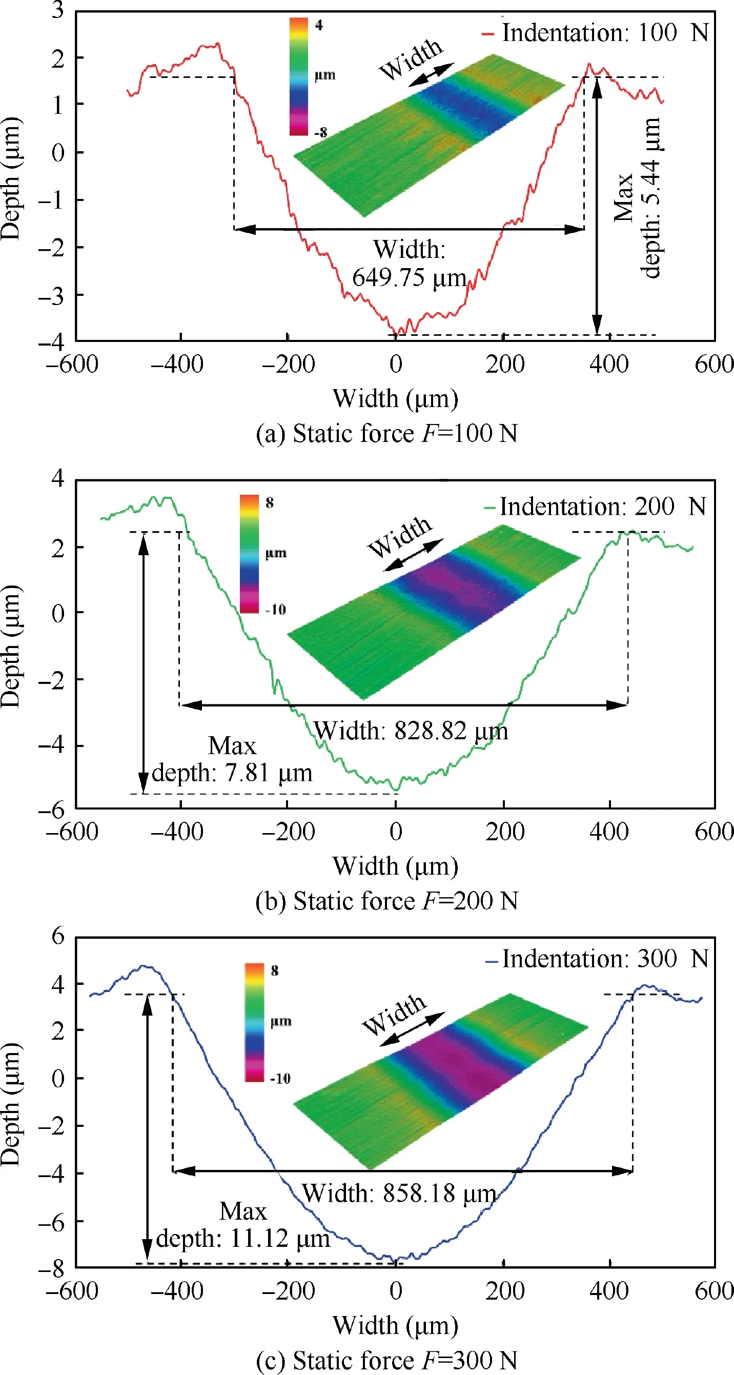
Fig. 11 Indentations under different static force.
Fig. 11 compares the indentations under different static forces by using IFM G4 (Infinite focus measurement). A software function named ‘‘Profile Form Measurement” is used tomeasuring the depth and width of indentations. It can be concluded that the static force is in positive proportion to the depth and width of plastic indentation.Therefore,considering the requirements of surface quality after USRP, overlap ratio mentioned above can be reasonable designed according to the different static forces.

Table 2 Indentation descriptions.
4.2. USRP on a curved blade
In the second set of experiments,the goal is to test the performance of the proposed fuzzy PID force controller on curved surface of the part. A real aero-engine blade with is used as one of the typical curved parts. Blade width ranges from 180 to 380 mm and the height of blade is about 700 mm. USRP is applied to the local areas on the back arc surface of the blade from blade height 300 mm to 450 mm,as shown in Fig.10.In order to guarantee that the curved part surface is uniformly covered by the USRP effects, the static force is required to be constant during the processing. Here the static force is set as 100 N, so the corresponding width of indentation is 650 μm according to the measured value in Table 2 and Fig. 11. Then, a series of paths covered by the machined part are generated with an overlap radio ov=85%,that is,the distance of adjacent paths’centers d is designed as 100 μm.Velocity of USRP tool along the path is set as 4 mm/s.
In order to compare the performance of USRP with and without fuzzy-PID force control, the blade is machined under the conditions of same static force 100 N. Fig. 12 shows the curves of the static force in two model. Since the force sensor is pre-loaded through the spring,the initial force monitored by force sensor is approximately 70 N. As shown in Fig. 12(a), it is obviously observed that the fluctuation of static force is very dramatic without force control and the max fluctuation of force is about 42.2 N during the USRP. On the contrary, it can be seen that the static force shows a stable fluctuation under the active and passive force control model in Fig. 12(b).When the force control model is turned on,the static force quickly reaches and stabilizes at 100 N,and the force deviation is significantly reduced to 4.2 N.
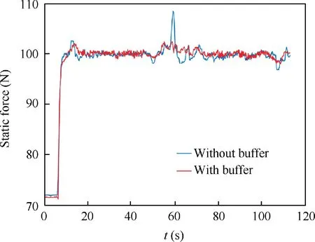
Fig. 13 Force curve with/without buffer.
During the USRP, the system should not only apply the force control in real time, but also seriously avoid the force changes caused by the machining instability. Sudden change of the surface shape is one of common problems in the machining instability. A ‘‘buffer” element in Eq. (15) is designed to restrict the maximum adjustment of USRP tool. Due to the designed ‘‘buffer”, the force variations caused by the machining instability are reduced significantly.Fig.13 shows the force change with and without ‘‘buffer” when the surface shape changes suddenly. It can be seen that the max static force can reach to 108.5 N, and the partial enlarged figure shows the dramatic fluctuation of force curve without ‘‘buffer”.Therefore,the‘‘buffer”can effectively reduce the force change caused by the machining instability.
The USRP part surface with and without force control is shown in Fig.14.The USRP tip without force control can only move along the original paths designed by off-line programming. The fluctuation of static force determines the surface quality and uniformity. The tool marks can be seen clearly on the part surface after USRP without force control. Meanwhile, the excessive static force in some areas will damage the surface, and the small static force in some areas cannot achieve the USRP effects. On the contrary, due to the active and passive compliant control of USRP, the surface quality is improved significantly (Fig. 15).
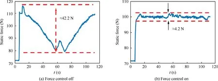
Fig. 12 Static force without/with active and passive force control model.
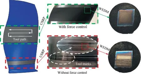
Fig. 14 Machined USRP areas with/without force control.

Fig. 15 Measured points of surface roughness.
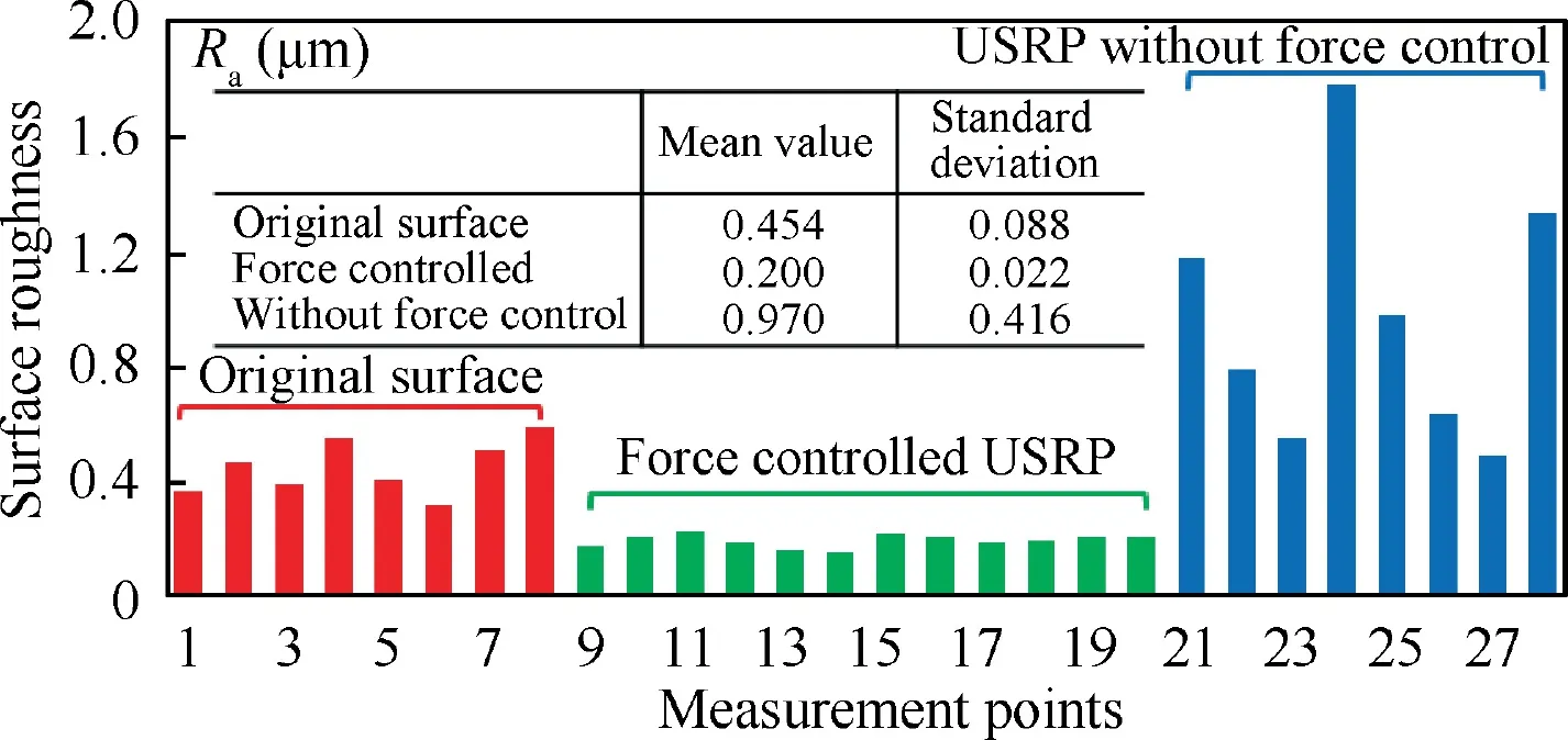
Fig. 16 Measurement results of surface roughness.
Surface roughness is used to evaluate the USRP effects of machined blade surface. As shown in Fig. 16, 28 points are measured on the original surface and the machined surface by a TR220 portable surface roughness tester. Point 1 to 8 are located at the original surface. Note that the original surface is shot peened and polished at first. Point 9 to 20 are located at the force controlled USRP areas. Furthermore,point 21 to 28 are the measured points in the USRP areas without force control. Under the same measurement settings, the surface roughness of each point are measured for three times,and the average value of them is taken to reduce the measurement errors. According to the mean value and standard deviation of measured points in three areas, the proposed active and passive compliant control method can not only reduce the roughness,but also guarantee the uniformity of the surface quality.
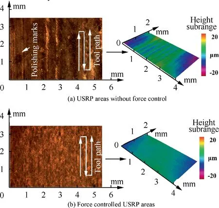
Fig. 17 Surface morphology of different USRP areas.
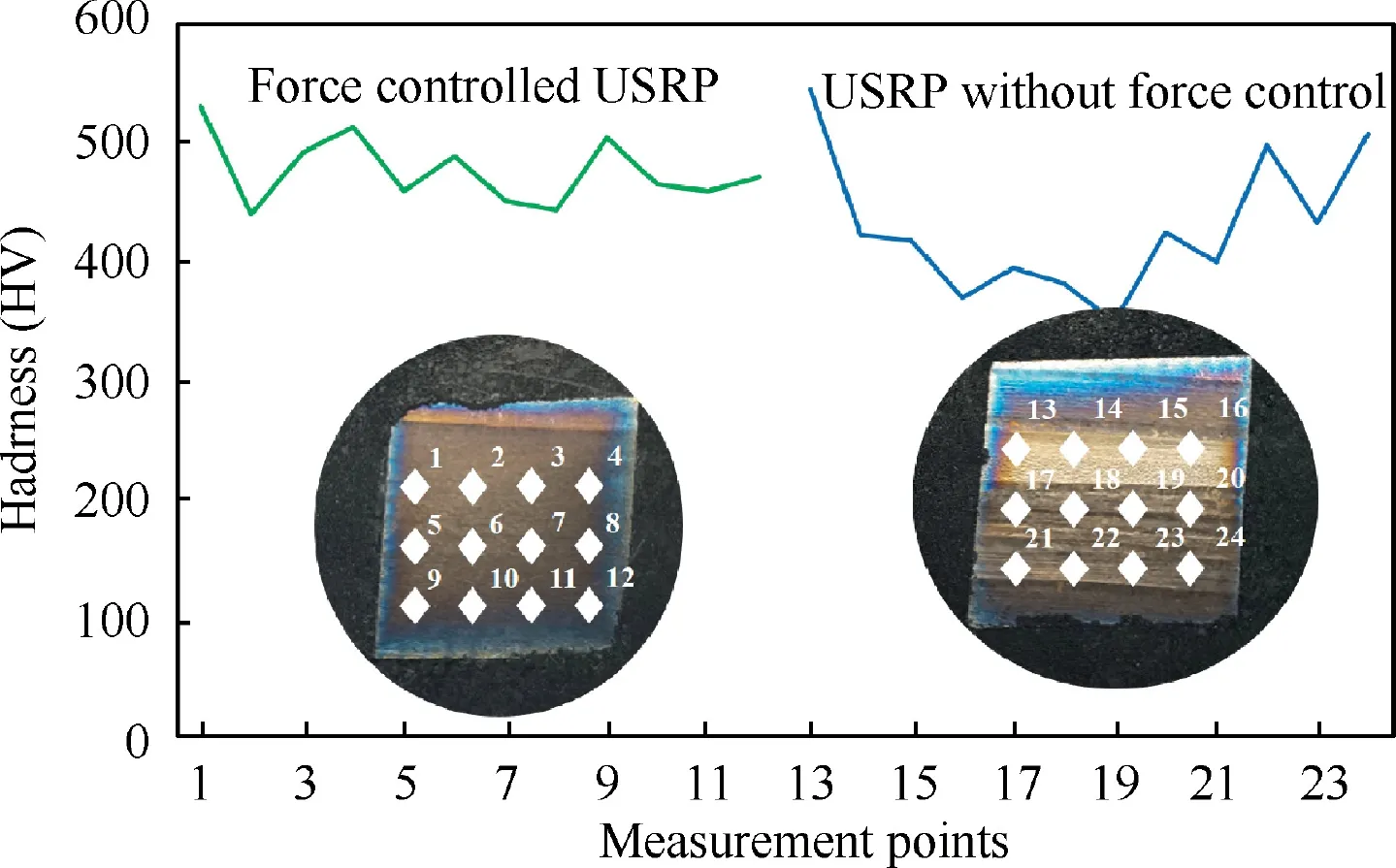
Fig. 18 Measured points of hardness.
In order to further compare the differences between these two USRP areas,fragments are cut by wire electrical discharge machining(WEDM),as shown in Fig.14.Then,the fragments are examined using metallurgical microscope(ZEISS Axiocam 105 color) and optical profilometer (Infinite focus measurement G4). Images of the surface morphology after USRP are shown in Fig. 17. It can be observed that the force controlled USRP areas is of better surface quality than the USRP areas without force control. Some polishing marks still exist in the Fig. 17(a), which implies that the static force is too small to flatten these marks on the original surface completely.In addition, some tool marks generated by USRP is conspicuous.These conspicuous marks are principally due to the large static force during the USRP. Obviously, these tool marks may easily generate the fatigue sources and fatigue cracks. On the contrary, under the active and passive compliant control of USRP, the force controlled USRP significantly decreases the heights of peaks and valleys on the part surface and guarantees a uniform surface quality, as shown in Fig.17(b). In addition,the height of peaks and valleys scatters from-4 to+4 μm in Fig.17(a),which is much bigger compared to that of the force controlled USRP areas within the range of -1 to + 1 μm in Fig. 17(b).
Ultrasonic surface rolling process as a promising technique can not only guarantee the surface quality of machined part,but also improve the hardness. As shown in Fig. 18,two fragments are cut from two USRP areas.The map in figure shows the measurement points.Since the original surface of the blade is shot peened,the hardness is about 360 ~380 HV.The hardness values in two USRP areas increase obviously compared with the original surface. However, it seems that force controlled USRP may generate more uniform distribution of hardness than that of USRP without force control.Combined with the previous analysis, the more stable the static force acted on the part surface,the more uniform effects may be generated by USRP.
5. Conclusion
Ultrasonic surface rolling on the part with curved surface is a complicated process.Static force is part and parcel to maintain the uniform USRP effects and obtain a higher-quality surface.Hence,an active and passive compliant USRP system is developed in this paper.Compared with some existing conventional USRP tools, the compliant USRP tool with spring and force sensor is designed to produce the natural obedience deformation along part surface.The active force control method based on the fuzzy PID is employed to adjust the force in real time.Experimental results show that the curved part can be processed effectively.Also,this study holds the key to the application of USRP technique onto the part surface, especially to some curved parts,such as aero-engine blades,blisks,etc.Consequently, the active and passive compliant USRP system is a promising technique for the machining of some curved parts to make the surface more uniform.In the future,we will focus on the relationship between the static force and force-induced change of surface quality. Meanwhile, the optimization of USRP parameters will be studied to obtain a better surface quality.
The authors declare that they have no known competing financial interests or personal relationships that could have appeared to influence the work reported in this paper.
This work was sponsored by the National Natural Science Foundation of China (No. 51725503 and No. 51975214) and Innovation Program of Shanghai Municipal Education Commission(2019-01-07-00-02-E00068). The authors are also grateful for the support by Shanghai Technology Innovation Program of SHEITC(CXY-2015-001),Fok Ying Tung Education Foundation, and Young Program of Yangtze River Scholars.
 Chinese Journal of Aeronautics2022年7期
- Chinese Journal of Aeronautics的其它文章
- An online data driven actor-critic-disturbance guidance law for missile-target interception with input constraints
- Study on excitation force characteristics in a coupled shaker-structure system considering structure modes coupling
- Smooth free-cycle dynamic soaring in unspecified shear wind via quadratic programming
- High dynamic output feedback robust control of hydraulic flight motion simulator using a novel cascaded extended state observer
- Composite impact vector control based on Apollo descent guidance
- Optimal trajectory design accounting for the stabilization of linear time-varying error dynamics
