Capturability of 3D RTPN guidance law against true-arbitrarily maneuvering target with maneuverability limitation
Keo LI, Zhihui BAI, Hyo-Sng SHIN, Antonios TSOURDOS,Min-Je TAHK
a Department of Applied Mechanics, College of Aerospace Science and Engineering, National University of Defense Technology, Changsha 410073, China
b Institute of Aerospace Sciences, SATM, Cranfield University, Cranfield MK43 0AL, UK
c Department of Aerospace Engineering, Korea Advanced Institute of Science and Technology, Daejeon 34141, Republic of Korea
KEYWORDS Capture region;Lyapunov-like approach;Maneuverability Limitation;Realistic true proportional navigation;True-arbitrarily maneuvering target
Abstract The capturability of the Three-Dimensional (3D) Realistic True Proportional Navigation (RTPN) guidance law is thoroughly analyzed. The true-arbitrarily maneuvering target is considered, which maneuvers along an arbitrary direction in 3D space with an arbitrary but upperbounded acceleration. The whole nonlinear relative kinematics between the interceptor and target is taken into account.First,the upper-bound of commanded acceleration of 3D RTPN is deduced,using a novel Lyapunov-like approach.Second,the reasonable selection range of navigation gain of 3D RTPN is analyzed, when the maneuver limitation of interceptor is considered. After that, a more realistic definition of capture is adopted, i.e., the relative range is smaller than an acceptable miss-distance while the approaching speed is larger than a required impact speed. Unlike previous researches which present Two-Dimensional (2D) capture regions, the inequality analysis technique is utilized to obtain the 3D capture region, where the three coordinates are the closing speed,transversal relative speed, and relative range. The obtained capture region could be taken as a sufficient-but-unnecessary condition of capture.The new theoretical findings are all given in explicit expressions and are more general than previous results.
1. Introduction
Proportional Navigation (PN) guidance laws are widely used in the guidance system design for guided weapons like torpedoes, missiles, and exoatmospheric interceptors.In the nonlinear form, PN guidance laws can be categorized into two major classes: the interceptor velocity referenced class and the Line-of-Sight (LOS) referenced class.The first one mainly includes the Pure Proportional Navigation(PPN)guidance law and its variants.. For this class of PN, the commanded acceleration is required to be perpendicular to the interceptor’s velocity.Hence,they are usually used for endoatmospheric or underwater interception.
The LOS-referenced class of PN mainly includes True Proportional Navigation (TPN),Realistic True Proportional Navigation(RTPN),Generalized True Proportional Navigation (GTPN),, Ideal Proportional Navigation (IPN),and General Ideal Proportional Navigation (GIPN).For this class of PN,the commanded acceleration is required to be perpendicular to a direction related to LOS,which is more preferable for exoatmospheric interceptionand space rendezvous.
According to the PN’s unified approach,TPN is the primary LOS-referenced PN, whose commanded acceleration is perpendicular to LOS and is proportional to the product of the initial closing speed and the real-time LOS angular rate.RTPN is the practical implementation of TPN using the real-time closing speed to replace the initial closing speed.GTPN, IPN, and GIPN are certain extensions of TPN and RTPN and are said to be with larger capturability. However,they all have command projections along LOS, which is hard for practical implementation. Therefore, TPN and RTPN are still the most commonly used LOS-referenced PNs.
In common exoatmospheric interception scenarios,the performance of RTPN is close to that of TPN, since the closing speed between the interceptor and target varies very little during most of the guidance process.Compared with TPN,RTPN is more mathematically tractable. Thus, a lot of researches have been devoted to the performance analysis of RTPN.For example,C.D.Yang and C.C.Yanganalyzed the performance of Three-Dimensional (3D) RTPN against nonmaneuvering target and maneuvering target, based on the 3D nonlinear coupled relative kinematic equation set. However,in their work, the maneuvering target was guided by IPN.Garai et al.derived the approximate closed-form solution of 2D RTPN using the Adomian decomposition method,and then they calculated the capture region numerically assuming that the target acceleration is constant.With the help of the Modified Polar Coordinate system(MPC)and Modified Polar Variables (MPVs), Tyanproposed a phase plane method to study the capturability of 3D GIPN.Notice that,3D GIPN is an extension of 3D RTPN with an additional commanded acceleration along LOS; hence, the capturability of 3D RTPN can be directly obtained from the analysis results of 3D GIPN.
Ballistic warheads and spacecraft are trying to develop active maneuverability to escape from exoatmospheric interceptors. The escape acceleration could be along an arbitrary and time-varying direction in 3D space with an uncertain time-varying magnitude. The capturability of RTPN against nonmaneuvering target has been fully explored.However,concerning the capturability of RTPN or its extension like IPN and GIPN against maneuvering targets,existing literatures still suffer from on main drawback: only certain escape acceleration models of target have been discussed,which is not general enough for practical interception missions.Besides,in some literatures,the obtained capture region needs to be calculated numerically, which is not intuitive and may not be suitable for real-time missions because of calculation burden.Recently, Li et al.obtained the 2D capture region of 2D RTPN against the arbitrarily maneuvering target. Nevertheless, the target maneuvering acceleration was assumed to be just along the normal direction of LOS. Then, this is still not a real ‘‘arbitrarily maneuvering target”.
In this paper, the capturability of 3D RTPN is revisited.The whole nonlinear relative kinematics between the interceptor and target is considered and no linearization is utilized.The above-mentioned drawback of the target acceleration model is released. Unlike previous literatures, the maneuverability limitation of interceptor is considered, and the obtained capture region is expressed explicitly in 3D space.
First,a 3D relative kinematic equation set established in the LOS Rotation Coordinate(LRC)systemis considered to mitigate the cross-coupling issue that exists in the 3D relative kinematic equation set established in the traditional LOS coordinate system.In this way, the relative motion could be decoupled into the 2D relative motion in the Instantaneous Rotation Plane of LOS(IRPL,which is also the instantaneous engagement plane) and the rotation of this plane. Hence, the design and analysis of 3D guidance laws could be greatly simplified.A few 3D guidance laws were already devised and analyzed using this rotating LOS or similar coordinate system.Advantages of utilizing this type of coordinate system were also demonstrated. For example, Li et al.used this kinematic equation set to study the performance of a 3D Differential Geometric Guidance Law (DGGL); Shin et al.used this kinematic equation set to study the capturability of a 3D Finite Time Sliding Mode Guidance (FTSMG) law.
Second, the true-arbitrarily maneuvering target is considered. The target maneuvering acceleration is assumed to be along an arbitrary and time-varying direction in the 3D space,while its magnitude is also assumed to be arbitrary but upperbounded.A novel Lyapunov-like approachwhich has been proven to be a powerful tool in the field of missile guidance law design and performance analysis is utilized to obtain the upper-bound of commanded acceleration of 3D RTPN against this true-arbitrarily maneuvering target, and the selection range of the navigation gain of 3D RTPN is also thoroughly discussed.
After that, the capture region of 3D RTPN is analyzed using an inequality analysis technique.A more realistic definition of capture is adopted, i.e., the relative range is smaller than an acceptable miss distance while the approaching speed is larger than a required impact speed. This is more general compared with the previous nonzero miss-distance requirement.The deduced capture region is expressed explicitly in 3D space where the three coordinates are the closing speed,transversal relative speed, and relative range. The capture region deduced in this paper could be taken as a sufficientbut-unnecessary condition of capture.
The over structure of this paper is given as follow:an introduction of the main contents of this paper is given at first. In the preliminaries section, preliminaries including the engagement geometry, relative kinematics, and research assumptions are addressed.The Capturability Analysis section provides the main performance analysis results of 3D RTPN, including upper-bound of commanded acceleration, selection range of navigation gain, and 3D capture condition, etc. Finally, the Conclusion section concludes this study after demonstrating the effectiveness of the new theoretical findings using numerical simulation examples in the Numerical Simulation section.
2. Preliminaries
The 3D engagement geometry is depicted in Fig. 1.
For the simplicity of capturability analysis of 3D RTPN,this paper assumes that:
(1) The interceptor and target are taken as point-masses.
(2) The dynamic lags of the interceptor and target are neglected.
(3) The gravity is neglected.
(4) No guidance or control error is considered.
Traditionally, 3D pursuit is handled by constructing two independent guidance laws in the vertical and horizontal planes of the LOS coordinate system and taking their crosscoupling effect into account,as shown in Refs.[17,19,21].This approach might complicate the description of the relative motion due to the cross-coupling effect and introduce some auxiliary variables. Establishing the kinematic equation set in LOS Rotation Coordinate system (LRC) could ease the complexity of the description of 3D relative kinematics.The relative motion in LRC can be divided into two decoupled submotions:
(1) The relative motion in the instantaneous osculating plane of the interceptor and the target spanned by the relative position and velocity vectors, which is also called ‘‘the instantaneous engagement plane” or ‘‘the Instantaneous Rotation Plane of LOS (IRPL)”.
(2) The rotation of this plane.
The kinematic equation set of LOS is shown as below,

where eis the unit vector along LOS, and ethe unit vector along the LOS angular velocity, e= e× ethe unit normal vector of LOS;e,e,and eform the bases of LRC;eand econstitute IRPL;ω=ωeis the angular velocity of LOS and ωthe 3D LOS rate;Ω=Ωeis the angular velocity of IRPL and Ωthe IRPL rotation rate.
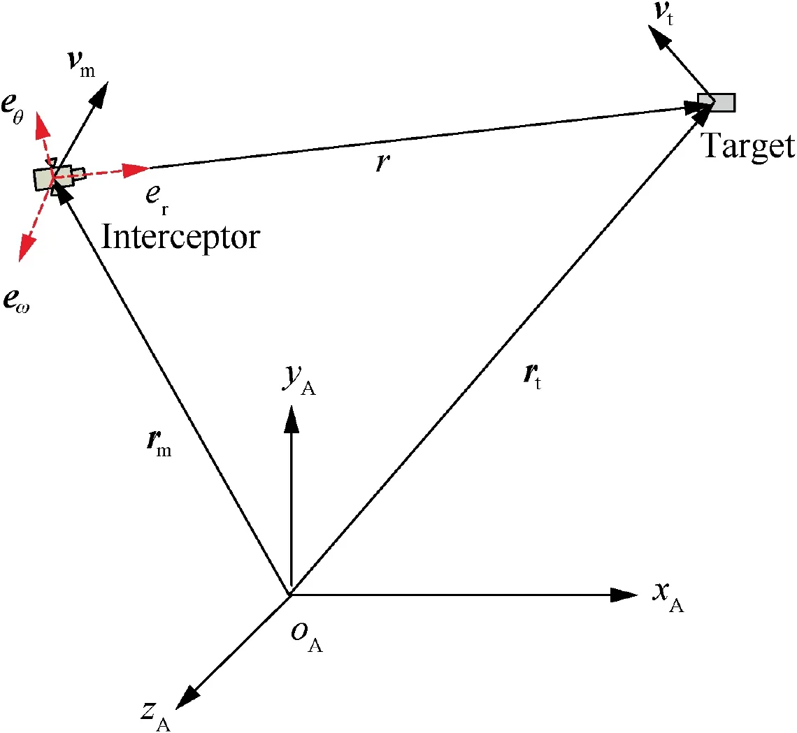
Fig. 1 3D engagement geometry.
Note that, if eis initially defined as the unit vector along the LOS angular velocity and the motion of the LRC frame(e, e, e) is calculated by integrating Eq. (1), as stated in Ref. [16] where LRC is called ‘‘LOS fixed coordinate system”,then ωis initially positive and could be either positive or nonpositive during the guidance process. In Refs. [4–6], eis defined as the real-time unit vector along the LOS angular velocity, and hence ωis defined to be always nonnegative.Concerning the value of Ω, it could be either positive or nonpositive, no matter which definition of eis adopted. In this paper, for the continuities of ω(t) and (e(t), e(t), e(t)), the definitions of ωand epresented in Ref. [16] are adopted.
The relative position vector is defined as

where the overdot means the first-order time derivative;v is the relative velocity vector;vand vare the velocity vectors of the target and interceptor, respectively. Note that, in this paper,the closing speed is defined as v= ˙r, the transversal relative speed is defined as v= rω, and the approaching speed between the interceptor and target is defined as the absolute value of the closing speed, i.e., |v|, which is always nonnegative.
Taking the derivative of Eq. (3) with respect to time yields

where N is the navigation gain.
For the guidance system Eq.(4),the initial values of system states are r(0) = r, ˙r(0 )= ˙r, ω(0) = ω, and Ω(0) = Ω.Note that, for the exoatmospheric interception scenario, it is usually assumed that the initial closing speed is quite smaller than zero.
The target acceleration is assumed to be arbitrary and timevarying, which satisfies where α is the total upper-bound of the target maneuvering acceleration.

According to the above Eqs. (6) and (7), the magnitude of the target maneuvering acceleration is arbitrary and timevarying but subjected to an upper-bound, while its direction can be along an arbitrary and time-varying direction in 3D space. This is a real ‘‘arbitrarily maneuvering target”, which is more general compared with previous literatures.
3. Capturability analysis
When exploring the capturability of LOS-referenced PNs, it is usually assumed that the interceptor has infinite maneuverability, and hence the obtained capture region is quite large, as shown in Refs.. Although in some papersthe maneuverability limitations of the interceptor and target are considered,the obtained capture region needs to be calculated numerically, which is not intuitive enough and brings calculation burden.
In this section, the capturability of 3D RTPN is restudied.At first, the upper-bound of commanded acceleration of 3D RTPN against the true-arbitrarily maneuvering target with upper-bounded acceleration is deduced. Then, considering the maneuverability limitation of interceptor, the reasonable selection range of the navigation gain of 3D RTPN is analyzed. After that, the 3D capture region of 3D RTPN is obtained, where the three coordinates are the closing speed,transversal relative speed, and relative range.
3.1. Upper-bound of commanded acceleration
Traditionally, the capture of target is commonly defined by
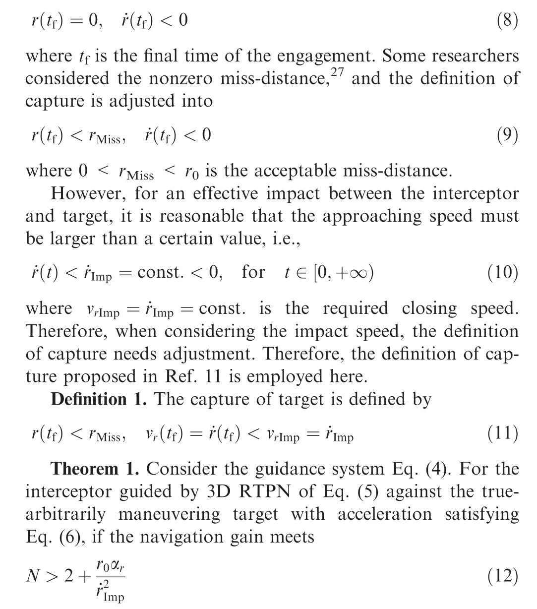
and the closing speed satisfies
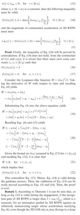
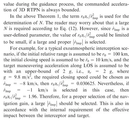
3.2. Selection range of navigation gain
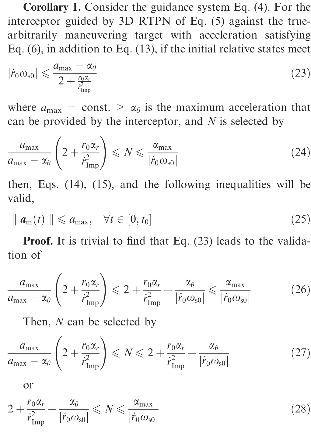
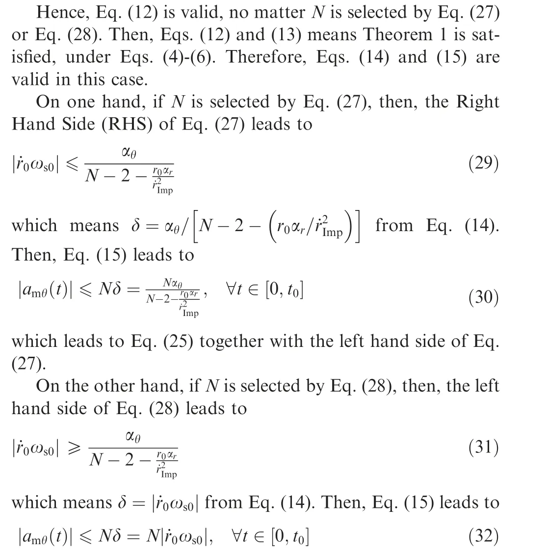
For practical exoatmospheric interception missions, the interceptor’s maneuverability must be limited. For certain initial relative states between the interceptor and target, through proper selection of the navigation gain N, the commanded acceleration of 3D RTPN will not exceed the physical limitation of the interceptor. This will be shown in the following corollary.
which leads to Eq. (25) together with RHS of Eq. (28).
Note that Eqs. (27) and (28) lead to Eq. (24). Then, the proof of this corollary is over.
Remark 2. According to Corollary 1, when Eq. (23) is satisfied, the selection range of the navigation gain of 3D RTPN is Eq. (24), which can be divided into two parts, i.e., Eqs. (27)and (28). Besides, from Eqs. (23) and (24) it can be seen that,for certain αand α, it is better for the interceptor to have a large maneuverability, which lead to a looser condition on the initial relative states and a larger selection range of the navigation gain of 3D RTPN.
For PN, it is commonly required that the interceptor’s maneuverability is several times of the target’s maneuverability, for example, a= 4α. Then, if r= 100 km, ˙r=-10 km/s, ˙r= -8 km/s, α= 2 g, α= 2 g, and ω= 2 × 10rad/s, then, Eq. (23) is satisfied and Eq.(24) indicates that 2.7075 < N ≤3.92. This is different from the engineering experience that N should be selected by N ∊[3,5 ] for PN guidance laws.However, one should know that, a large N may cause the interceptor to use the maximum acceleration to cope with the large initial heading error or the strong target maneuverability during the guidance process.Then, N ∊[3,5 ] may not be the proper selection for the navigation gain of 3D RTPN.
3.3. Capture region
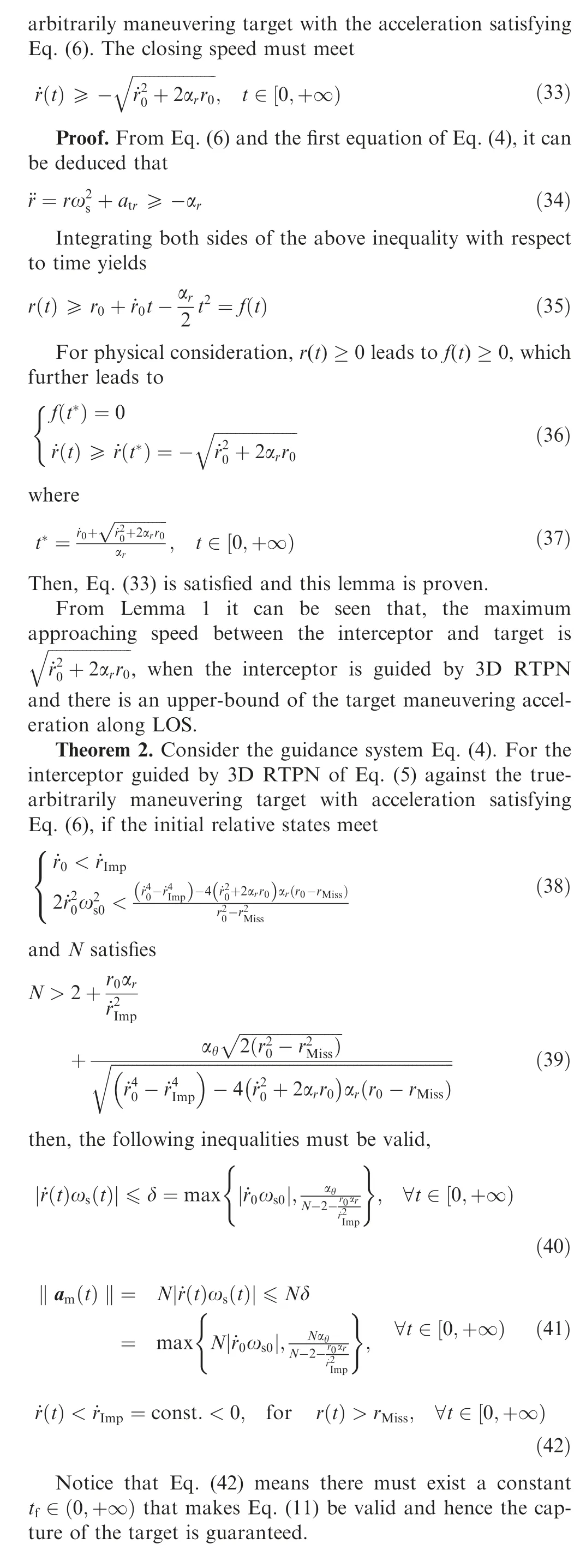
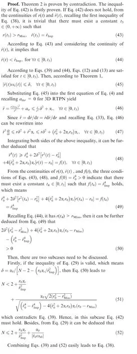
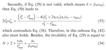
Combining Eqs. (38) and (54) easily leads to Eq. (39).
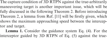
After the proof of Eq. (42), inequalities of Eqs. (40) and(41)are proven.It is trivial that Eqs.(39)and(42)means Theorem 1 is valid for t=+∞, under Eqs. (4)-(6). Hence, Eqs.(40) and (41) can be directly deduced from Eqs. (14) and (15).
Therefore, inequalities of Eqs. (40)-(42) are also proven.
Remark 3.According to Theorem 2,if(A)the interceptor is with infinite maneuverability, (B) the initial relative states of the interceptor and target are located in the region of Eq.(38), and (C) the navigation gain of 3D RTPN satisfies Eq.(39), no matter what type of escape model the target adopts,Eq. (42) will be valid during the engagement and the interceptor guided by 3D RTPN will definitely capture the truearbitrarily maneuvering target.
Although Theorem 2 has presented an initial capture condition Eq. (38) and a requirement on the navigation gain of 3D RTPN, i.e., Eq. (39), however, the maneuver limitation of the interceptor has not been considered, which makes Theorem 2 impractical. The capture region of 3D RTPN with maneuver limitation will be discussed in the following corollary.
Corollary 2. Consider the guidance system Eq. (4). For the interceptor guided by 3D RTPN of Eq.(5)against the arbitrarily maneuvering target with acceleration satisfying Eq. (6), if the initial relative states satisfy Eq. (23) and
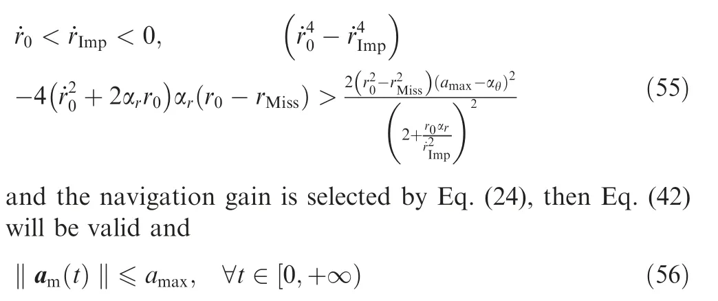
Proof.According to the proof process of Corollary 1,if Eq.(23) is satisfied, then Eq. (26) is valid and N could be selected by Eq. (24). Then, it is trivial to find that the Left Hand Side(LHS) of Eqs. (24) and (25) lead to the validities of Eqs. (38)and (39). Therefore, Theorem 2 is valid under Eqs. (4)-(6),which means Eq. (42) is valid.
Let t=+∞. Then, Eqs. (23), (24), and (42) lead to the validity of Corollary1, under Eqs. (4)-(6). Hence, Eq. (25) is valid, which leads to Eq. (56) for t=+∞. The proof is over.
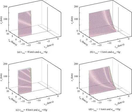
Fig. 2 3D capture region of 3D RTPN.
Remark 4. According to Corollary 2, for the interceptor guided by 3D RTPN with acceleration saturation of aagainst the true-arbitrarily maneuvering target whose acceleration satisfying Eq. (6), if the initial relative states between the interceptor and target are located in the region bounded by Eqs. (23) and (55), N could be selected by Eq. (24), then Eq.(42) will be valid and the capture of the target described by Eq. (11) will be guaranteed. Furthermore, Eq. (56) will be valid,which means the commanded acceleration of 3D RTPN will never reach the acceleration saturation of the interceptor.
Therefore,the region bounded by Eqs.(23)and(25)can be taken as the capture region of 3D RTPN. For a better expression of the capture region of 3D RTPN, recalling v= ˙r,v=rω,and v= ˙r,Eqs.(23)and(25)could be rewritten as
Capture Condition 1.


For the capture region of 3D RTPN defined by Eqs. (57)and (58), rand vare user-defined parameters, ais the maximum acceleration that the interceptor can provide,and αand αare the upper-bounds of the target maneuvering acceleration along eand e, respectively. Therefore, the capture region can be drawn in the 3D space spanned by v,v, and r.
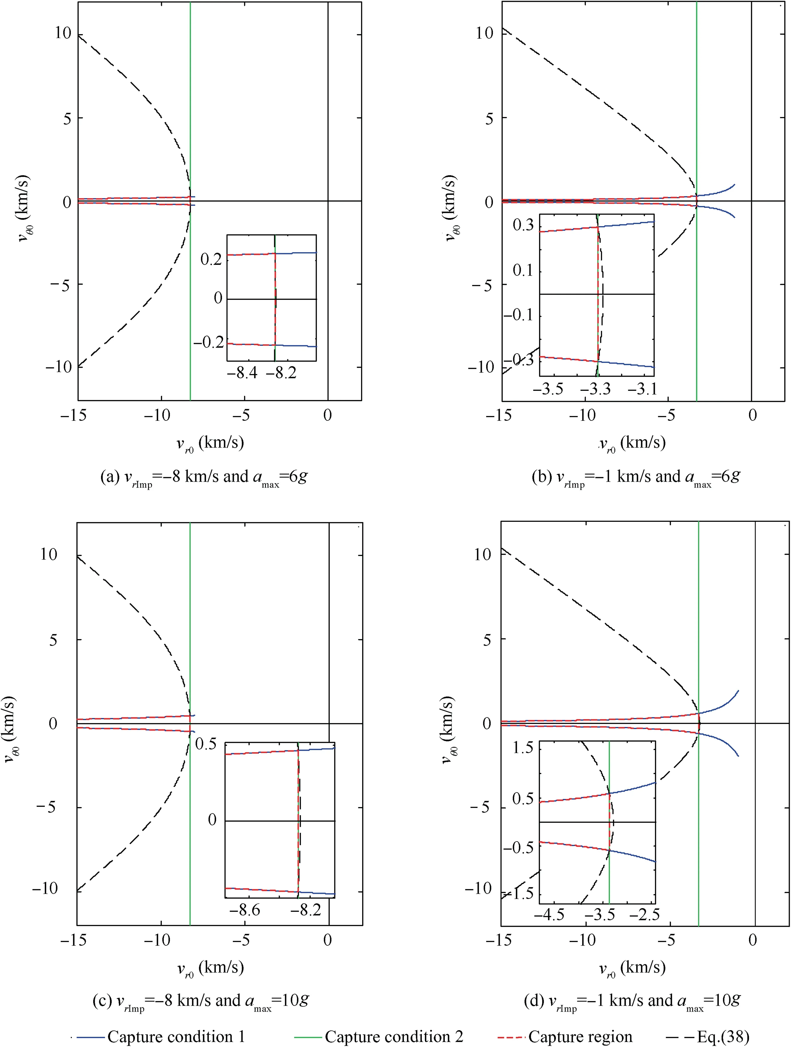
Fig. 3 2D capture region of 3D RTPN on the (vr0, vθ0) plane when r0 is fixed.
For example,if r=0.2 m,v=-8 km/s or-1 km/s(for comparison), α= 2 g, α= 2 g, and a= 6 g or 10 g(for comparison),the 3D capture region of 3D RTPN is shown in Fig. 2. It can be seen that a smaller impact speed requirement or larger interceptor maneuverability leads to a larger capture region. For a better understanding, if the initial relative range is further fixed as r= 100 km, the capture region could be drawn on the relative velocity plane, as shown in Fig. 3. It can be seen that the capture region defined by Eqs.(57) and (58) are located in the region defined by Eq. (38).According to Fig. 2 and Fig. 3, when the initial approaching speed between the interceptor and the target is large enough,Capture Condition 1, which represents the capture requirement on the initial relative states caused by the maximum maneuverability of the interceptor, becomes the main capture condition of the arbitrarily maneuvering target.
Remark 5.The capture region of 3D RTPN obtained in this paper is actually a sufficient-but-unnecessary condition for the capture of the true-arbitrarily maneuvering target, since the target maneuvering acceleration is arbitrary which is not exactly known to the interceptor and the inequality analysis method is utilized. Although the analysis results obtained in this paper are conservative in some degree, they are still very general and could be used as guidance to the guidance and control system design of the practical exoatmospheric interceptor.
Remark 6.According to the relative kinematic equation set Eq.(4),the target acceleration along e,i.e.,a,will not influence the varying of the relative range r and that of the 3D LOS rate ω.Hence,it has little influence on the capturability of 3D RTPN.
4. Numerical simulations
In this section,numerical simulation examples are simulated to demonstrate the validities of the theorems proposed in this paper.
The capture region of 3D RTPN guarantees the capture of the true-arbitrarily maneuvering target and simultaneously avoids the saturation of commanded acceleration is given in Section III, which is consisted of two capture conditions, i.e.,Eqs. (57) and (58). The effectiveness of this capture region could be validated by Monte-Carlo simulation method. The authors have done numerous simulations to demonstrate the validity and effectiveness of the capture region of 3D RTPN proposed in this paper. However, for the length of this paper,two initial condition sets of the interceptor and the target will be adopted to demonstrate the validities of Theorem 1,Corollary 1,Theorem 2,and Corollary 2 in the following text.The first one is in the capture region and near the boundary,while the second one is outside the capture region. The initial states of the missile and target in this case are shown in Table 1.
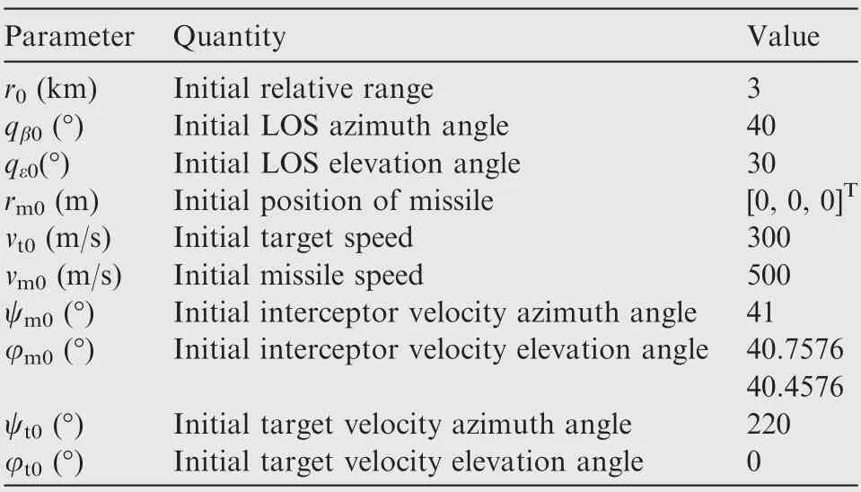
Table 1 Initial states of interceptor and target.
Let r= 0.2 m, v= -600 m/s. Two kinds of target maneuvering acceleration are considered. The first one is a constant maneuvering acceleration,which is a=10 m/s,aθ = 20 m/s, a= 10 m/s, while the second one is a sinusoidal maneuver, which is a= 9 + sin(2πt + π/2) m/s,a= 2[9 + sin(2πt + π/2)]m/sand a= 9 + sin(2πt +π/2) m/s. Hence, α= 10 m/s, α= 20 m/s, and α=10 m/s.The maximum acceleration that the interceptor can provide is assumed to be a= 50 m/s. The relative states of the missile and target and the capture region of 3D RTPN are shown in Fig. 4.
For φ=42.9576°,it has(v,v)=(-747.0275,38.3920)which is denoted as ‘‘Initial states 1”, while for φ= 69.4270°, (v, v)=(-9924.1177, 325.8391) which is outside the capture region and is denoted as ‘‘Initial states 2”. It is trivial to find that ‘‘Initial states 1” and ‘‘Initial states 2”both satisfy Eq.(38)of Theorem 2.Hence,according to Eq.(39) of Theorem 2, if

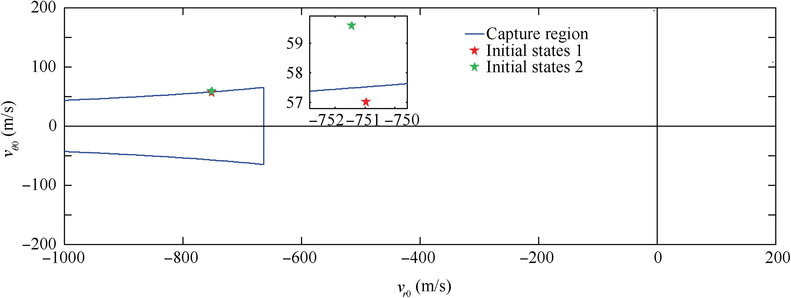
Fig. 4 2D capture region of 3D RTPN and the initial relative states on the (vr0, vθ0) plane.
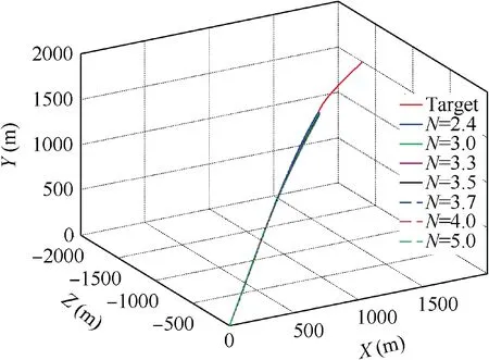
Fig.5 3D trajectories of the interceptor and target(Initial states 1 and constant target maneuver).
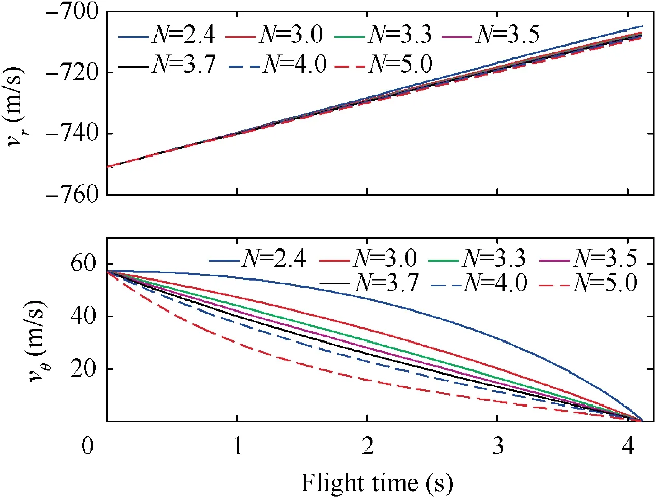
Fig.6 Closing speed and transversal relative speed(Initial states 1 and constant target maneuver).
the target can be captured, which means Eq. (42) will be valid for both ‘‘Initial states 1” and ‘‘Initial states 2”. Furthermore,since Theorem 2 is a sufficient-but-not-necessary condition, a smaller N may also lead to the validness of Eq.(42)in simulation examples. Nevertheless, Eq. (59) gives an analytical bottom line for the selection of the navigation gain of 3D RTPN.
Although the satisfactory of Eq.(59)leads to the validity of Eq. (42), the commanded acceleration of 3D RTPN may exceed the physical limitation of the interceptor, i.e., ‖a(t)‖>a. Therefore, a more suitable N may need to be further selected.It is easy to find that the inequality of Eq.(23)is valid for the ‘‘Initial states 1”, since it is in the capture region.Hence,according to Corollary 1,N could be selected according to Eq.(24)to guarantee Eqs.(42)and(56)simultaneously,i.e.,

While for the ‘‘Initial states 2”, as it is outside the capture region, the inequality of Eq. (23) is not satisfied. Then, a proper N to guarantee Eq. (56) together with Eq. (42) might not be able to find analytically. According to above analysis,for detailed comparison, N = 2.4, 3.0, 3.3, 3.5, 3.7, 4.0, and 5.0 are selected for both‘‘Initial states 1”and‘‘Initial states 2”.
The sampling period is selected as T = 10 ms. When the closing speed vbecomes nonnegative, which means the interceptor is leaving the target, the simulation stops. Then, the miss distance is approximated by the Zero-Effort-Miss ZEM = r|ω|/v,using the last data before vturns its sign.
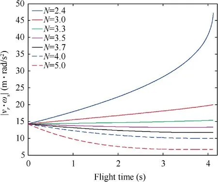
Fig. 7 Absolute value of |vr∙ωs| (Initial states 1 and constant target maneuver).
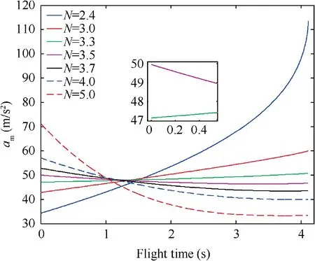
Fig. 8 Magnitude of commanded acceleration of 3D RTPN(Initial states 1 and constant target maneuver).
4.1. Constantly maneuvering target
Firstly,the‘‘Initial states 1”is utilized.The target adopts constant maneuvering acceleration of a= 10 m/s, a= 20 m/s,a=10 m/s.The simulation results are shown in Figs.5–10.
The 3D trajectories of the interceptor and the target under Initial states 1 when the target adopts constant maneuver are shown in Fig. 5. It can be seen that, for all navigation gains of N = 2.4, 3.0, 3.3, 3.5, 3.7, 4.0, and 5.0, the miss distance is smaller than 0.01 m.
The closing speed and the transversal relative speed under Initial States 1 when the target adopts constant maneuver are shown in Fig. 6. It can be seen that, the absolute value of the closing speed |v| is always larger than |v|=600 m/s. This together with the fact that all the miss distances are smaller than 0.01 m means the target can be captured for all navigation gains of N = 2.4, 3.0, 3.3, 3.5, 3.7, 4.0, and 5.0.Then, the validity of Theorem 2 is demonstrated. It can also be seen that the transversal relative speed decreases more rapidly as N grows.

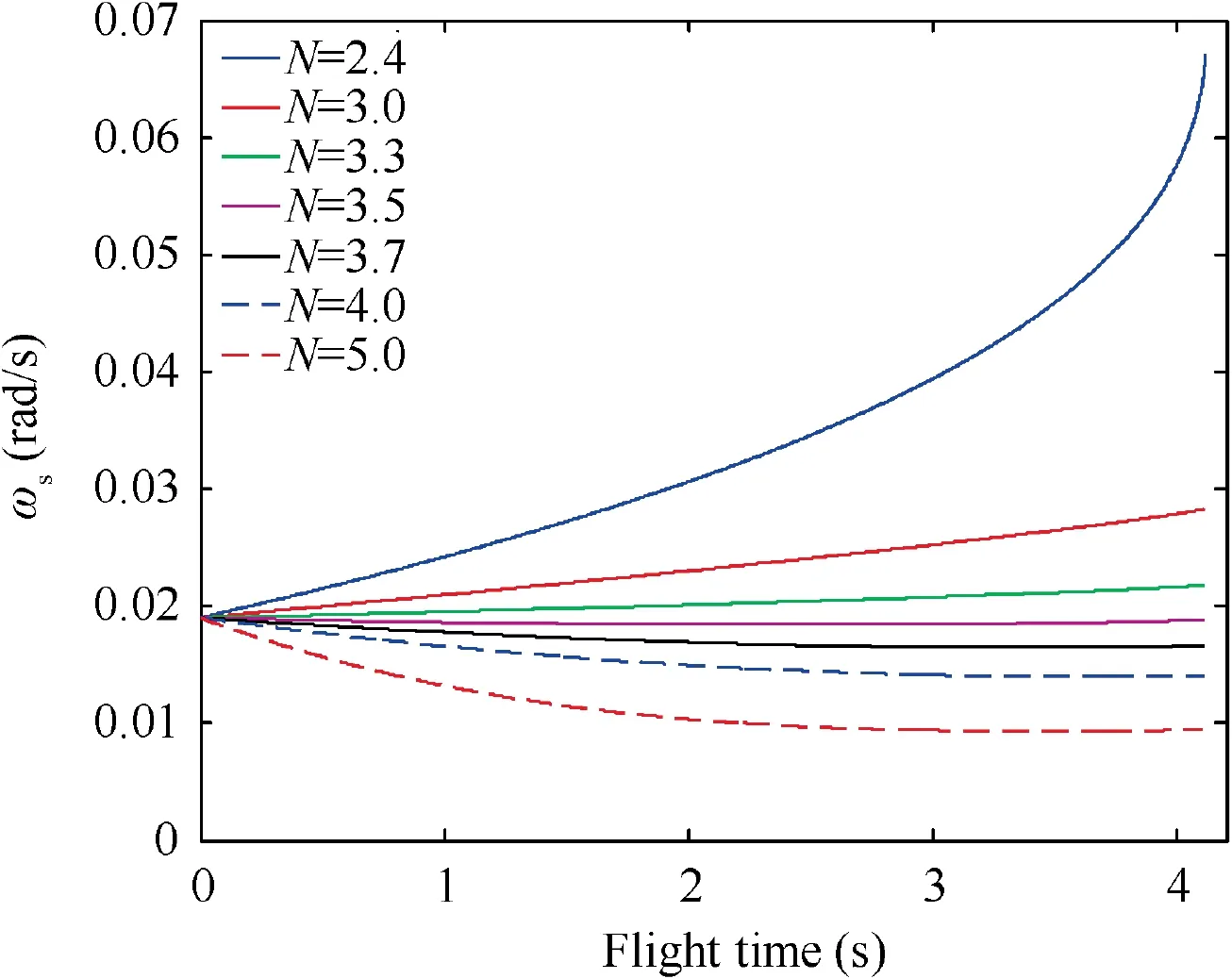
Fig. 9 3D LOS rate (Initial states 1 and constant target maneuver).
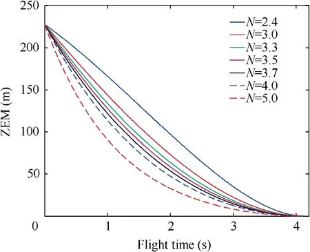
Fig. 10 Zero-miss-effort (Initial states 1 and constant target maneuver).
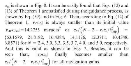
Furthermore, according to Eq. (15) of Theorem 1, ais always smaller than Nδ={151.5789, 65.4545, 54.2466,49.9643, 52.8194, 57.1020, 71.3775} for N = 2.4, 3.0, 3.3,3.5, 3.7, 4.0, and 5.0, respectively. This is also valid as shown in Fig. 8. Besides, it can be seen that, only for N = 3.5, the commanded acceleration of RTPN is below the physical limitation of the interceptor a.That is because N=3.5 is properly chosen according to Eq. (24) of Corollary 1. And according to Corollary 2,the capture of the target can be guaranteed while the acceleration saturation of the interceptor can be avoided. Then, Corollary 1 and Corollary 2 are demonstrated.
The 3D LOS rate under Initial states 1 when the target adopts constant maneuver is shown in Fig. 9. It can be found that, RTPN with N = 2.4, 3.0, 3.3, and 3.5 cannot guarantee the convergence of ωduring the guidance process. For N = 3.7, 4.0, and 5.0, the convergence of ωcan be guaranteed. And it can be seen that, as N grows, the final value of ωdecreases, which leads to small ZEM.
The ZEM under Initial states 1 when the target adopts constant maneuver is shown in Fig. 10. It can be seen that all the ZEM curves are always decreasing during the guidance process. And as N grows, the decrease speed of ZEM increases.
For comparison, when the initial relative states are outside the capture region,i.e.,‘‘Initial states 2”,the simulation results are shown in Figs. 11–16.
The 3D trajectories of the interceptor and the target under Initial states 2 when the target adopts constant maneuver are shown in Fig. 11. It can be seen that, for all navigation gains of N = 2.4, 3.0, 3.3, 3.5, 3.7, 4.0, and 5.0, the miss distance is smaller than 0.01 m.
The closing speed and the transversal relative speed under Initial States 2 when the target adopts constant maneuver are shown in Fig. 12. It can be seen that, |v| is always larger than |v|=600 m/s. This together with the fact that all the miss distances are smaller than 0.01 m means the target can be captured for N = 2.4, 3.0, 3.3, 3.5, 3.7, 4.0, and 5.0. Then,the validity of Theorem 2 is demonstrated.interceptor, i.e., Eq. (56). Although there might be a possible navigation gain between 3 and 5 to make Eq. (56) valid, however, it may need to be selected through plenty of numerical simulation examples, rather than being directly selected according to the analytical inequality of Eq. (24).
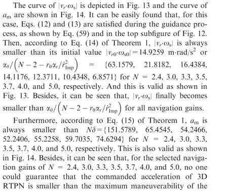

Fig. 11 3D trajectories of the interceptor and target (Initial states 2 and constant target maneuver).
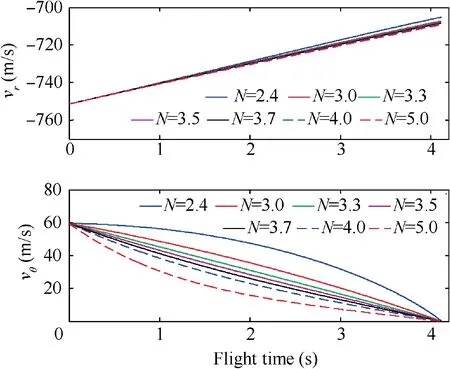
Fig. 12 Closing speed and transversal relative speed (Initial states 2 and constant target maneuver).
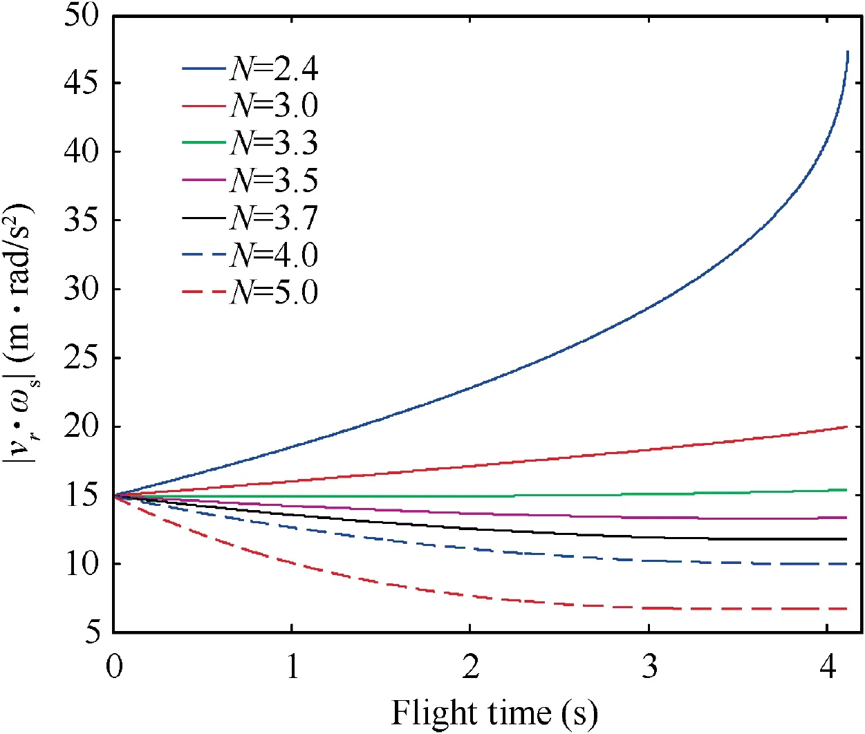
Fig. 13 Absolute value of |vr∙ωs| (Initial states 2 and constant target maneuver).
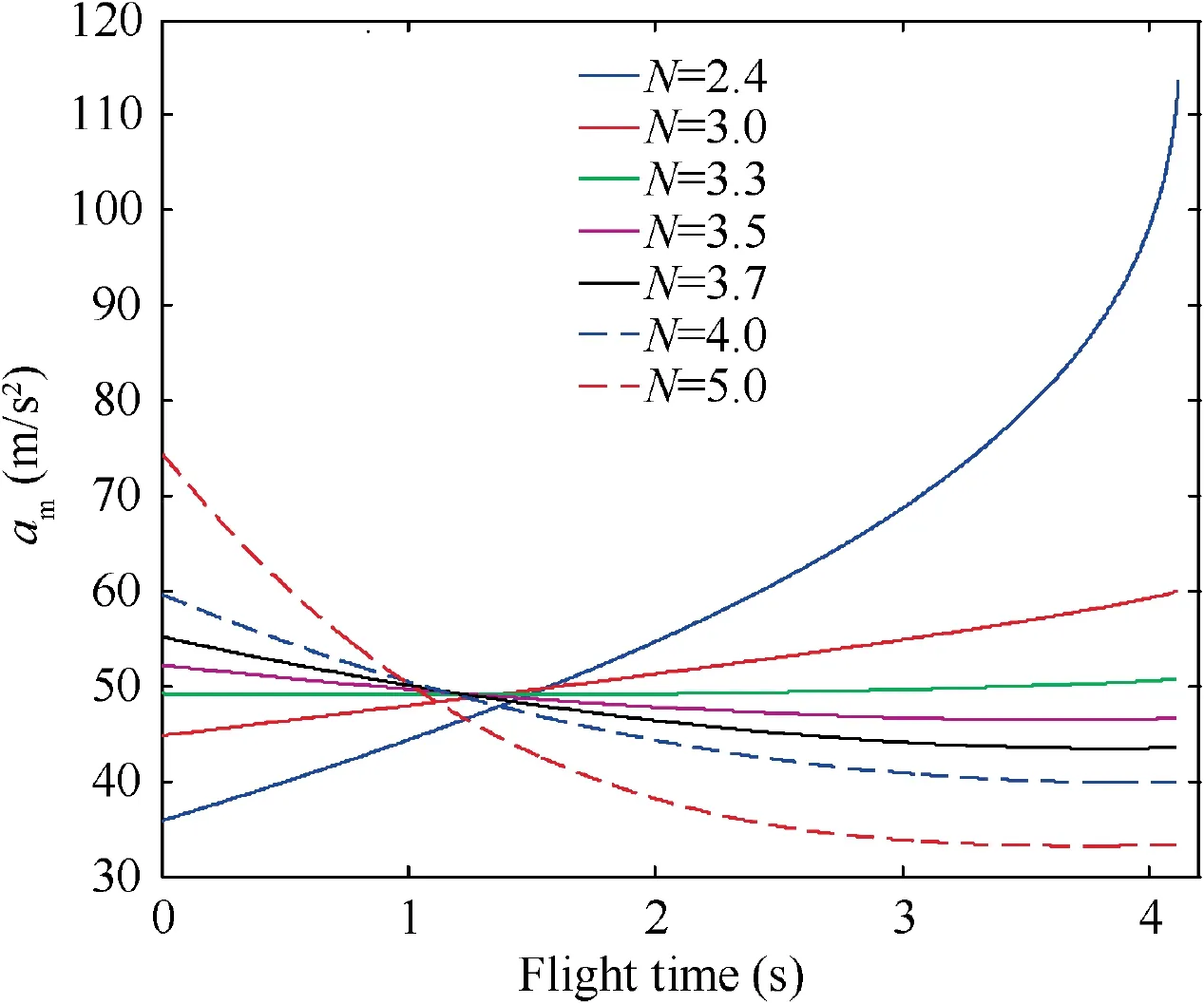
Fig. 14 Magnitude of commanded acceleration of 3D RTPN(Initial states 2 and constant target maneuver).
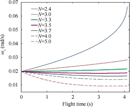
Fig. 15 3D LOS rate (Initial states 2 and constant target maneuver).
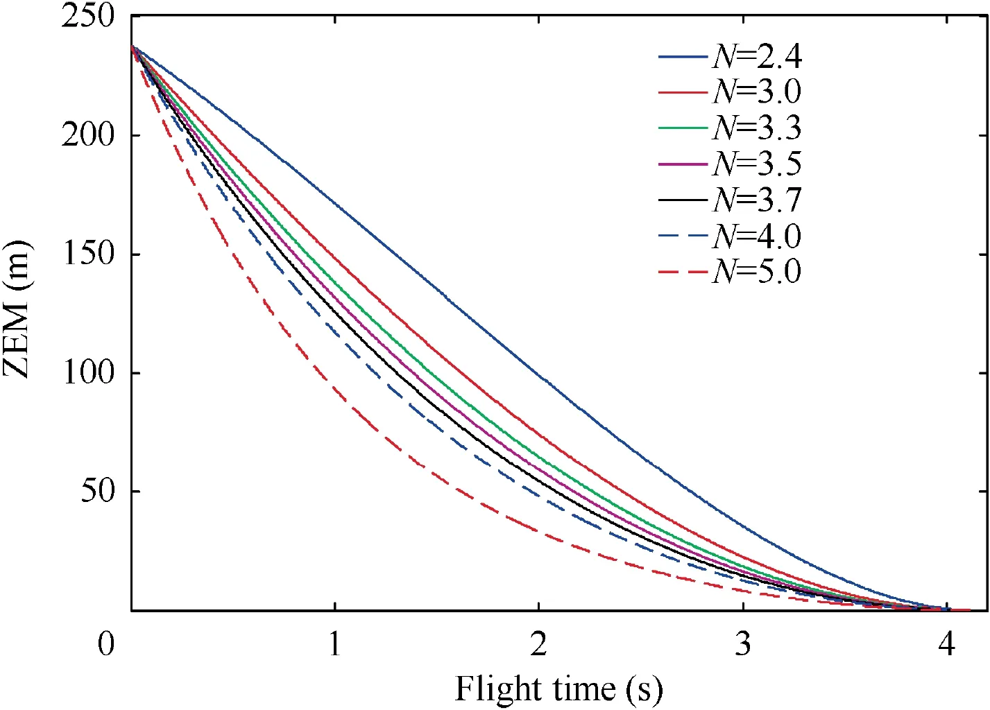
Fig. 16 Zero-miss-effort (Initial states 2 and constant target maneuver).
The 3D LOS rate under Initial states 2 when the target adopts constant maneuver is shown in Fig.15.It can be found that,RTPN with N<3.5 cannot guarantee the convergence of ωduring the guidance process.For N=3.7,4.0,and 5.0,the convergence of ωcould be guaranteed. And it can be seen that, as N grows, the final value of ωdecreases, which leads to small ZEM.
The ZEM under Initial states 2 when the target adopts constant maneuver is shown in Fig. 16. It can be seen that all the ZEM curves are always decreasing during the guidance process. And as N grows, the decrease of ZEM also speeds up.
4.2. Sinusoidally maneuvering target
In this subsection, the target adopts the sinusoidal maneuvering acceleration of a=9+sin(2πt+π/2)m/s,a=2[9+sin(2πt + π/2)] m/sand a= 9 + sin(2πt + π/2) m/s.Hence, it also has α= 10 m/s, α= 20 m/s, and α=10 m/s.Firstly,the‘‘Initial States 1”is utilized.The simulation results are shown in Figs. 17–22.
The 3D trajectories of the interceptor and the target under Initial states 1 when the target adopts sinusoidal maneuver are shown in Fig.17.It can be seen that,for all navigation gains of N = 2.4, 3.0, 3.3, 3.5, 3.7, 4.0, and 5.0, the miss distance is smaller than 0.01 m.
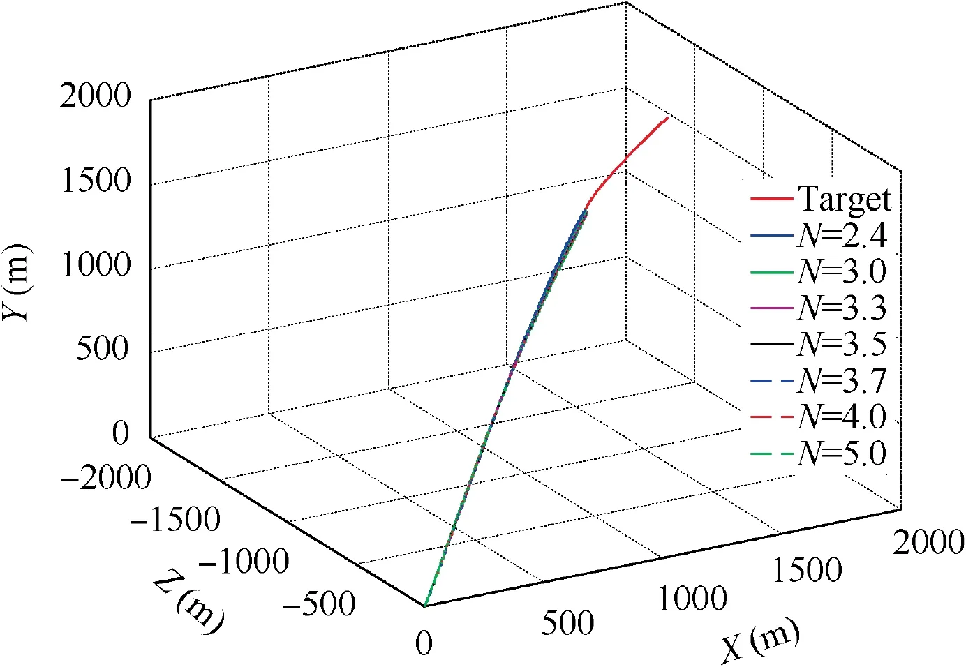
Fig. 17 3D trajectories of the interceptor and target (Initial states 1 and sinusoidal target maneuver).
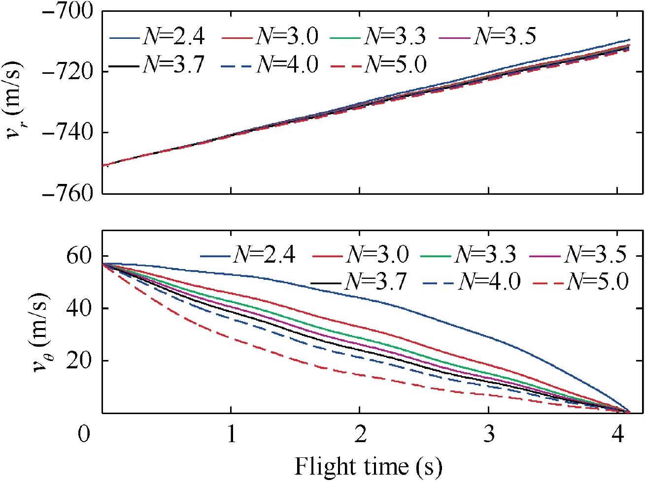
Fig. 18 Closing speed and transversal relative speed (Initial states 1 and sinusoidal target maneuver).

Fig. 19 Absolute value of |vr∙ωs| (Initial states 1 and sinusoidal target maneuver).
The closing speed and the transversal relative speed under Initial states 1 when the target adopts sinusoidal maneuver are shown in Fig. 18. It can be seen that, |v| is always larger than |v|=600 m/s. This together with the fact that all the miss distances are smaller than 0.01 m means the target can be captured for N = 2.4, 3.0, 3.3, 3.5, 3.7, 4.0, and 5.0. Then,the validity of Theorem 2 is demonstrated.

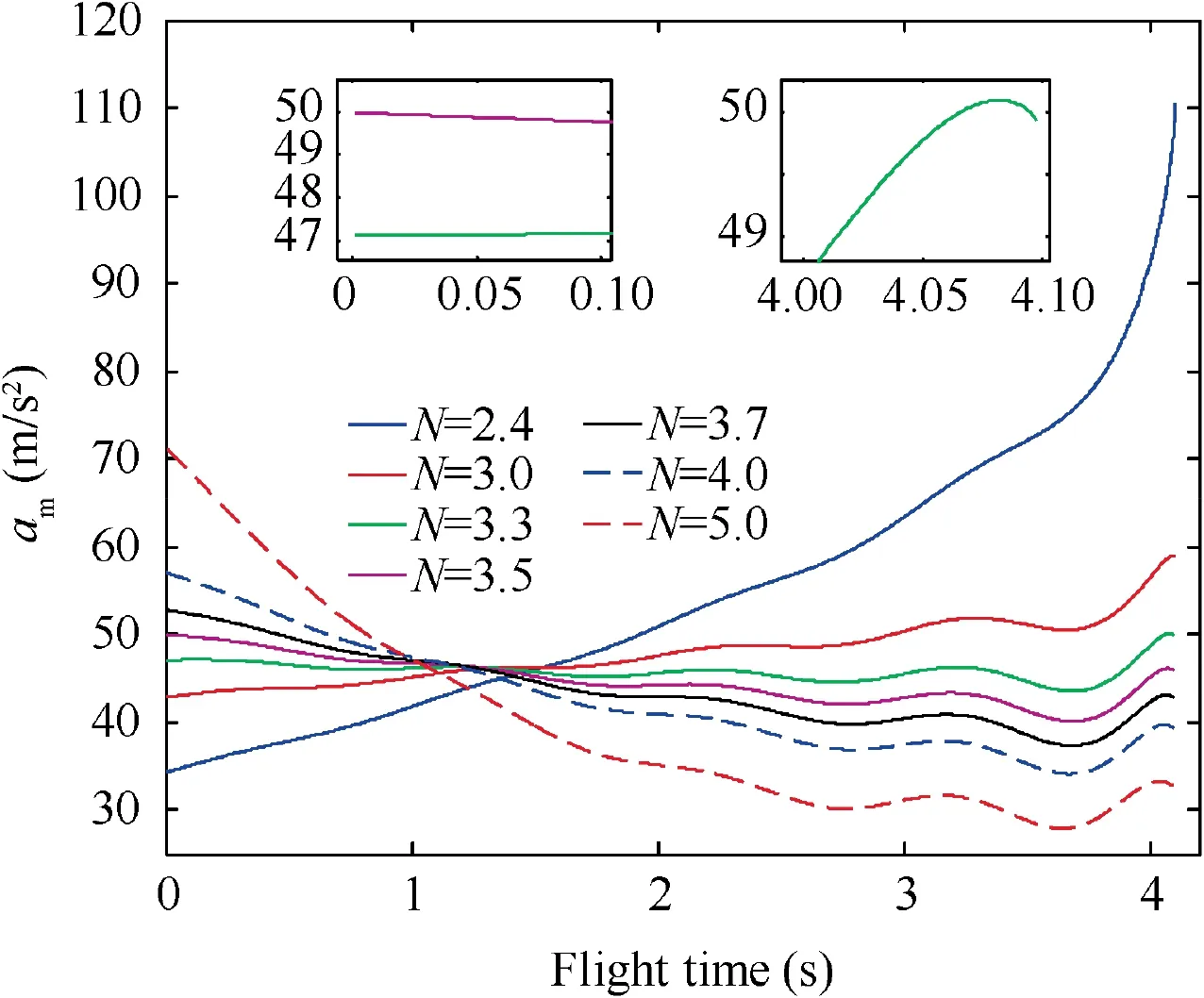
Fig. 20 Magnitude of commanded acceleration of 3D RTPN(Initial states 1 and sinusoidal target maneuver).
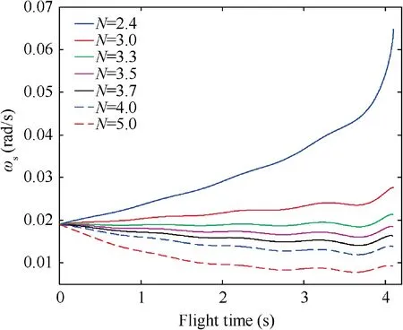
Fig. 21 3D LOS rate (Initial states 1 and sinusoidal target maneuver).
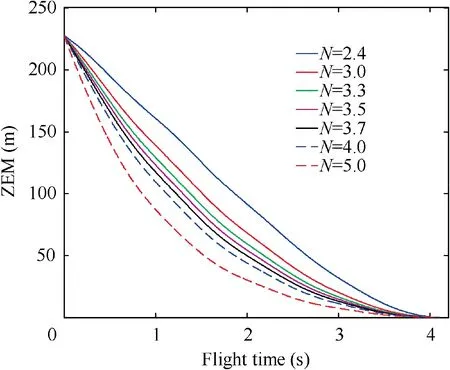
Fig. 22 Zero-miss-effort (Initial states 1 and sinusoidal target maneuver).

Furthermore, according to Eq. (15) of Theorem 1, ais always smaller than Nδ={151.5789, 65.4545, 54.2466,49.9643, 52.8194, 57.1021, 71.3776} for N = 2.4, 3.0, 3.3,3.5, 3.7, 4.0, and 5.0, respectively. This is also valid as shown in Fig. 20. Besides, it can be seen that, only for N = 3.5, the commanded acceleration of RTPN is below the physical limitation of the maneuverability of interceptor, i.e., a. That is because N = 3.5 is properly chosen according to Eq. (24) of Corollary 1. And according to Corollary 2, the capture of the target can be guaranteed while the acceleration saturation of the interceptor can be avoided. This is in accordance with the case of ‘‘Initial states 1 and constant target maneuver”.Then, Corollary 1 and Corollary 2 are demonstrated.
The 3D LOS rate under Initial States 1 when the target adopts sinusoidal maneuver is shown in Fig. 21. It can be found that, the curve of ωis wavy for all navigation gains.This is caused by the sinusoidal maneuvering acceleration of the target. And it can be seen that, as N grows, the final value of ωdecreases, which leads to small ZEM. This principle is similar to the cases where the target adopts constant maneuver.
The ZEM under Initial States 1 when the target adopts sinusoidal maneuver is shown in Fig. 22. It can be seen that all the ZEM curves are wavy and always decreasing during the guidance process. And as N grows, the decrease of ZEM also speeds up.
For comparison, when the initial relative states are outside the capture region,i.e.,‘‘Initial states 2”,the simulation results are shown in Figs. 23–28.
The 3D trajectories of the interceptor and the target under Initial states 2 when the target adopts sinusoidal maneuver are shown in Fig.23.It can be seen that,for all navigation gains of N = 2.4, 3.0, 3.3, 3.5, 3.7, 4.0, and 5.0, the miss distance is smaller than 0.01 m.
The closing speed and the transversal relative speed under Initial states 2 when the target adopts sinusoidal maneuver are shown in Fig. 24. It can be seen that, |v| is always larger than |v|=600 m/s. This together with the fact that all the miss distances are smaller than 0.01 m means the target can be captured for N = 2.4, 3.0, 3.3, 3.5, 3.7, 4.0, and 5.0. Then,the validity of Theorem 2 is demonstrated.
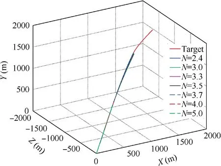
Fig. 23 3D trajectories of the interceptor and target (Initial states 2 and sinusoidal target maneuver).
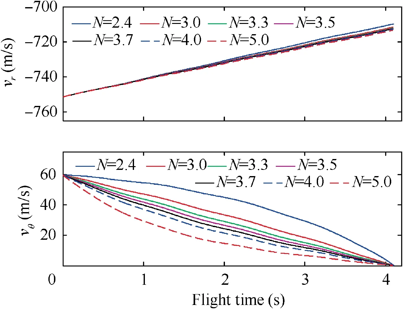
Fig. 24 Closing speed and transversal relative speed (Initial states 2 and sinusoidal target maneuver).
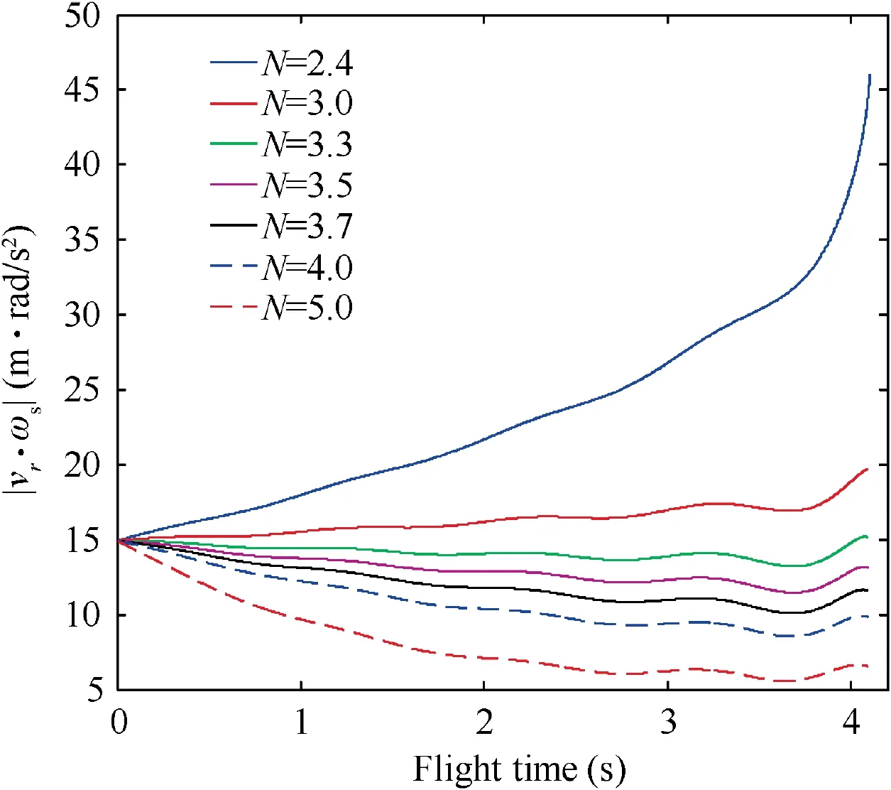
Fig. 25 Absolute value of |vr∙ωs| (Initial states 2 and sinusoidal target maneuver).
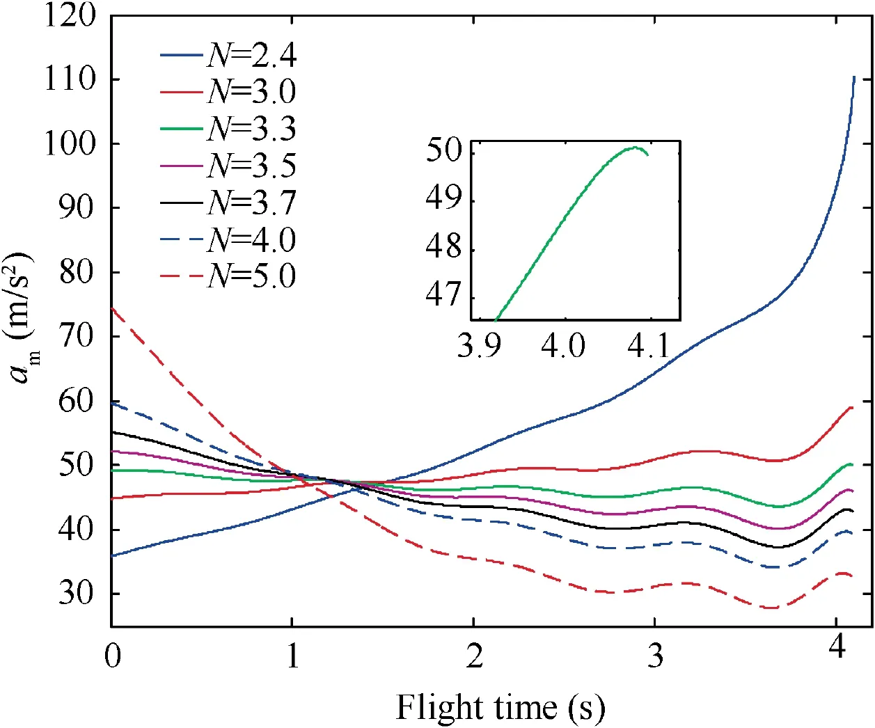
Fig. 26 Magnitude of commanded acceleration of 3D RTPN(Initial states 2 and sinusoidal target maneuver).
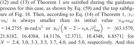
The curve of |v∙ω| is depicted in Fig. 25 and the curve of aare shown in Fig. 26. It can be easily found that Eqs.(12) and (13) of Theorem 1 are satisfied during the guidance process for this case, as shown by Eq. (59) and the top subfigure of Fig. 24. Then, according to Eq. (14) of Theorem 1, |v-∙ω| is always smaller than its initial value |v∙ω|
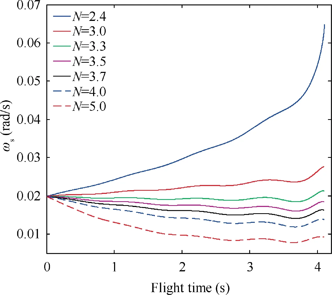
Fig. 27 3D LOS rate (Initial states 2 and sinusoidal target maneuver).

Fig. 28 Zero-miss-effort (Initial states 2 and sinusoidal target maneuver).
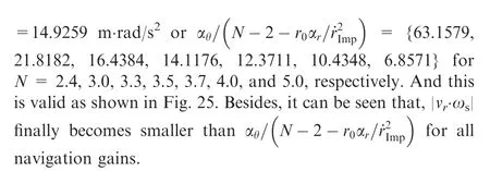
Furthermore, according to Eq. (15) of Theorem 1, ais always smaller than Nδ={151.5789, 65.4545, 54.2466,52.2406, 55.2258, 59.7035, 74.6294} for N = 2.4, 3.0, 3.3,3.5, 3.7, 4.0, and 5.0, respectively. This is also valid as shown in Fig.26.Besides,it can be seen that,for the selected navigation gains of N = 2.4, 3.0, 3.3, 3.5, 3.7, 4.0, and 5.0, no one could guarantee Eq. (56). Although there might be a possible navigation gain between 3-5 to make Eq.(56)valid,however,it may need to be selected through plenty of numerical simulation examples, rather than being directly selected according to the analytical inequality of Eq.(24).This is in accordance with the case of ‘‘Initial states 2 and constant target maneuver”.
The 3D LOS rate under Initial states 2 when the target adopts sinusoidal maneuver is shown in Fig. 27. It can be found that, the curve of ωis wavy for all navigation gains.This is caused by the sinusoidal maneuvering acceleration of the target. And it can be seen that, as N grows, the final value of ωdecreases, which leads to small ZEM. This principle is similar to the cases when the target adopts constant maneuver.
The ZEM under Initial states 2 when the target adopts sinusoidal maneuver is shown in Fig.28.It can be seen that all the ZEM curves are wavy and always decreasing during the guidance process. And as N grows, the decrease of ZEM also speeds up.
According to the above simulation results, when the initial relative states are in the capture region of 3D RTPN defined by Corollary 2 proposed and the navigation gain of 3D RTPN is properly selected according to Eq.(24)of Corollary 1,the truearbitrarily maneuvering target whose maneuvering acceleration satisfying Eq. (6) can be captured, i.e., the capture definition of Eq.(11)will be valid,and the commanded acceleration of 3D RTPN will not exceed the maneuverability limitation of the interceptor, i.e., Eq. (56).
5. Conclusions
(1) The capturability of 3D RTPN against the truearbitrarily maneuvering target is thoroughly analyzed,when the maneuver limitation of interceptor is taken into account. Using a novel Lyapunov-like approach,the upper-bound of commanded acceleration of 3D RTPN is obtained. The reasonable selection range of the navigation gain is also analyzed. After that, the 3D capture region is obtained,whose three axes are the closing speed, transversal relative speed, and relative range.When the initial or real-time relative states are located in the capture region and the navigation gain of 3D RTPN is properly chosen according to the analytical inequality obtained, the true-arbitrarily maneuvering target could be captured, and the commanded acceleration of 3D RTPN will not exceed the maneuverability limitation of interceptor.
(2) The new theoretical findings obtained in this paper are based on the Lyapunov-like approach and the inequality analysis technique. No linearization assumption or simplification is utilized. Hence, the obtained theoretical results are globally general. The boundary of the obtained capture region is an analytical function of parameters of acceptable miss-distance,required closing speed, target maximum maneuvering acceleration along LOS, target maximum maneuvering acceleration along the normal direction of LOS,and interceptor maximum maneuvering acceleration. Hence, the capture region could be previously calculated according to the apriori information about the interceptor and target.
(3) Only deterministic problem is investigated in this paper.In the future work,the influences of measurement errors on the capture region of 3D RTPN may need further discussion.Besides,the ideal relative dynamics is considered here. The dynamic lags of the interceptor seeker and thrusters also need further investigations.
Declaration of Competing Interest
The authors declare that they have no known competing financial interests or personal relationships that could have appeared to influence the work reported in this paper.
This work was supported in part by the National Natural Science Foundation of China (No. 12002370) and in part by the Hunan Provincial Natural Science Foundation of China(No. 2019JJ50736).
 Chinese Journal of Aeronautics2022年7期
- Chinese Journal of Aeronautics的其它文章
- An online data driven actor-critic-disturbance guidance law for missile-target interception with input constraints
- Study on excitation force characteristics in a coupled shaker-structure system considering structure modes coupling
- Smooth free-cycle dynamic soaring in unspecified shear wind via quadratic programming
- Active and passive compliant force control of ultrasonic surface rolling process on a curved surface
- High dynamic output feedback robust control of hydraulic flight motion simulator using a novel cascaded extended state observer
- Composite impact vector control based on Apollo descent guidance
