Kinematic modeling and control of a novel pneumatic soft robotic arm
Hongwei LI, Yan XU, Chao ZHANG, Huxiao YANG
School of Aeronautics and Astronautics, Zhejiang University, Hangzhou, Zhejiang, China
KEYWORDS Arm control;Kinematics;Repeated precision;Soft robotic arm;Trajectory tracking
Abstract A novel soft robotic arm(SRA)composed of two soft extensible arms(SEAs)and a soft bendable joint (SBJ) for space capture systems is presented in this paper. A diamond origami pattern was applied in the design of the SEAs,and large deformations of the SEAs in positive pressure were simulated using the nonlinear finite element method.A kinematic model of the SRA using the Denavit–Hartenberg method based on the assumption of constant curvatures was proposed. A closed-loop model-free control system based on a PID controller was developed using real-time data from a vision sensor system. The kinematic model and closed-loop model-free control system are experimentally evaluated on an SRA prototype by four experiments. The experimental results demonstrate that the derived kinematic model can finely describe the movement of the SRA and that the closed-loop control system can control the SRA to reach the desired destination or trajectory within an acceptable error and performs well in long-term repeated operations.
1. Introduction
Soft robotic arms (SRAs) have attracted great research attention recently due to their satisfactory environmental adaptability, relative safety, abundant degrees of freedom (DoF) and low cost. There have been many studies related to SRAs in the healthcare field,wearable devicesand environment exploration.Until now, SRAs have rarely been used in space capture systems.Compared with rigid capture robot systems,the reaction forces from the environment are widely distributed on the surface of the SRAs during capture,which can reduce the impact damage. Therefore, the SRAs are very suitable for capture tasks that include collisions.Due to its large continuous ability to deform,the SRAs will be able to capture noncooperative targets well. For example, the SRAs can be used to capture the space debris to improve the safety of the spacecrafts and the satellites for in-orbit services.The cameras can be attached to the end of the SEAs to monitor the status of the spacecrafts.
The SRAs are usually inspired by a variety of soft creatures,such as trunks,octopus,and tongues.In general,the structure of a soft robotic arm consists mainly of pneumatic muscle actuators (PMAs),fluidic elastomer actuators (FEAs)and origami-based actuators.PMAs and FEAs have the advantages of a high force-to-weight ratio, abundant DoF and small size.A soft robotic arm was inspired by the octopus,can bend to 90°after pressurizing a single chamber.Ishiyama et al.proposed a PMA-based jumping robot, which only takes 0.33 s to shift from the stance phase to the lift-off phase and achieves a jump height of 100 mm. Marchese and Rusdesigned a soft fluidic elastomer manipulator which was capable of fully advancing through an S-shaped pipe. The difficulty in the structural design of the SRA is to achieve multidegree-of-freedom and large-workspace movement in a simple system as much as possible. Origami-inspired structures can achieve large deformations (contraction, elongation, bending and twisting).Chen et al.proposed a bellow-based extensible soft robotic arm that had an elongation ratio of 25% and a contraction ratio of 75%. Yu et al.designed a soft crawling robot based on origami that could achieve linear locomotion by repeated elongation and contraction. Therefore, several origami-inspired structures can be combined to design SRAs.
Modeling and control are key technologies of the SRAs.Approximate models and satisfactory control performances can be achieved by rational assumptions and control systems combined with control algorithms, machine learning, computer vision, etc. A dynamic model of the SRA was identified using a system identification procedure,with iterative learning control applied to improve the tracking performance.Al-Ibadi et al.presented a PMA-based soft robotic arm and developed a cascaded position control system.The experimental results demonstrate that PMAs can respond quickly after actuation,and a small control error can be achieved.Marchese and Ruskinematically modeled a multi-segment arm based on a piecewise constant curvature assumption and controlled the soft arm using an array of cascaded PI-PID controllers to track target points. Santoso et al.designed an origamiinspired,cable-driven continuum manipulator module and utilized an inverse kinematic control scheme to control the manipulator to follow a circular trajectory. In summary,most research works first focus on establishing static deformation or dynamic models,and then control systems are developed based on these models. However, there will be inevitable errors and uncertainties in the mechanical models derived due to the nonlinearity, hysteresis and fatigue effects of the soft materials.For example, the mechanical behaviors of soft materials will change after periodic movement.This will require the parameters in the static or dynamic SRA model to be modified periodically.Therefore,the nonlinearity,hysteresis and fatigue effects of soft materials make the modeling and control of the SRA very difficult.A model-free control may be more suitable for long-term SRA control.
The design of a novel SRA inspired by the human arm composed of two soft extensible arms(SEAs)and a soft bendable joint(SBJ)is presented. A kinematic model and a closedloop model-free control system of the SRA are developed and experimentally verified. The remainder of this paper is organized as follows: The design of the SRA, including SEA and SBJ, is presented in Section 2 along with the derivation of the kinematic model. A closed-loop model-free control approach is outlined in Section 3. Section 4 describes the experimental validation of the kinematic model and the closed-loop model-free control system.Finally,Section 5 summarizes a few concluding remarks and suggestions for future work.
2. Design and modeling
2.1. Soft robotic arm
The SRA is composed of two soft extensible arms(SEAs)and a soft bendable joint (SBJ). The SBJ consists of 4 elastic bellows and two nylon plates. The SEAs and bellows are developed by casting in 3D printed molds, and the nylon plates are 3D printed. The SEAs and bellows are hollow with a 2 mm thick wall. The SRA is composed mainly of silicon rubber(hardness:90), except for the nylon plates, and is actuated by inflatable gas channels.The 602-mm long SRA is composed of independently cast and serially concatenated modular segments.
The morphology of the SRA draws inspiration from the structure of the human arm, as shown in Fig. 1. However,the SRA presented here differs from the human arm in several ways. First, similar to the human arm, the SRA can bend by actuating the SBJ; however, the elbow joint morphology differs in that the SBJ has four circularly distributed pneumatic actuators, allowing it to bend in two directions. Second, the SRA has two SEAs corresponding to the upper arm and lower arm of the human arm; however, the arm morphology differs in that the SEA can realize axial elongation,allowing the SRA to operate in a larger workspace. Third, we have not yet designed an end manipulator for the SRA; hence, we attach a small ball marker on the end of the SRA, allowing an external vision sensor system to localize the end-position of the SRA.
The SRA is actuated by controlling the positive pressure between inside and outside of the chambers, which ensure the feasibility of the SRA working in space with vacuum environment. More specifically, before the SRA is sent into orbit,the SRA will be vacuumed to be in a folded state, and a gas compressor supplying the inflatable gas should be accompanied. Then, the SRA can operate on orbit just like on the ground by controlling the positive pressure in the chambers.
Compared with the PMA-based soft arm, the SRA can be actuated with a lower pressure. Compared with the FEAbased soft arm, the SRA has a larger elongation ratio. Compared with other origami-based designs, the SRA can achieve multiple types of motions due to more components assembled.However, the SRA cannot respond as quickly as PMAs after actuation due to its large chamber volumes. And the SRA behaves worse than FEAs in bending capacity.The fabrication process of origami-based structures is more complex than these two types of actuators.
2.2. Soft extensible arm
To realize a large linear tensile stroke and self-folding driving mechanism, the structural topology of the SEAs is designed based on a diamond origami pattern. The basic elements of the SEA are the isosceles triangles shown in Fig.2(a).The geometric relationship of the basic elements can be described as follows:

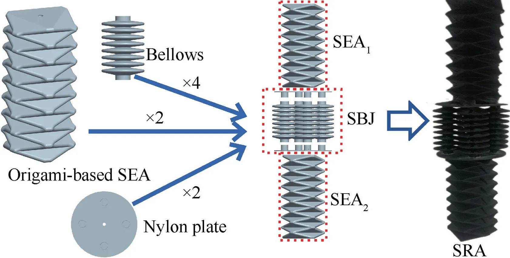
Fig.1 SRA is composed of two SEAs(SEA1 and SEA2)and one SBJ.
where b is the hypotenuse length, h is height, a is side length and α is base angle.
A thin shell of the SEAs is formed by repeating the basic element in the circumferential and axial directions (see Fig. 2(b)). After connecting the blue edge end to end, followed by folding along the green crease, the three-dimensional cylindrical thin wall of the SEA is finally provided(see Fig.2(c)).The length of AC(l)is defined as a,the crease angle is defined as β,the midpoint of side AC is defined as E,and the midpoint of BD is defined as F. It is obvious that l⊥l, l⊥land l⊥l. The top view of Fig. 2(c) is a regular hexagon, as shown in Fig. 2(d). Since E and F are the midpoints of AC and BD, respectively, we can obtain that ∠ECF = 30° from Fig. 2(d). Therefore, the following equations can be obtained:

where l, l, l, lare the length of EF, BE, BD, BC respectively.
In brief, the size of the basic element (land l) and the height of each layer (l) along the axial direction can be calculated if a and β are determined.Referring to the width of the human arm,a is set as 110 mm.For the value of crease angle β,the SEAs would lose the initial self-folding configuration with large β on the one hand and require a high pressurization pressure to elongate completely with small β on the other hand.Taking these factors into account, we finally set the crease angle β to 50°. Substituting a = 110 mm and β = 50° into Eq. (5), the single layer height l= 29.6 mm is obtained.Referring to the length of the human arm,the number of axial layers is set as 8;hence,the length of the SEAs(l)is 237 mm.In addition, to prevent fatigue failure attributed to stress concentration,a chamfer design with a radius of 2 mm was carried out at the creases and vertices of the SEAs. The final configuration of the origami-based SEAs is presented in Fig. 1.
The mechanical behaviors of the SEA during actuation were simulated and experimentally investigated. The axial displacement of a SEA model with length of 240 mm was measured by a laser displacement sensor, and the pressure in the chamber was measured by a pressure sensor, as shown in Fig. 3(a). A hyperplastic constitutive model was utilized to characterize the large deformations of silicone rubber in ABAQUS. The initial configuration of the SEA is shown in Fig. 3(b). When the SEA is operated with positive pressures, the SEA elongates axially (see Fig. 3(c)). The analysis results of the mechanical behaviors are in good agreement with the experimental results, including the axial displacements and deformed configurations. The maximal elongation of the SEA at an internal positive pressure of 20 kPa is 171 mm in the experimental results, which is close to the analysis results of 168.7 mm.These demonstrate the large linear tensile stroke of the SEA, and verify the measure system and simulation model simultaneously.
2.3. Soft bendable joint
The SBJ consists of four elastic bellows (B, B, B, B)installed circularly between two nylon plates, as shown in Fig. 4(a). The crest section radius of the bellows is 34 mm,and the trough section radius is 12 mm.The length of the bellows(l)is 122 mm,and the thickness of the nylon plates is 3 mm.
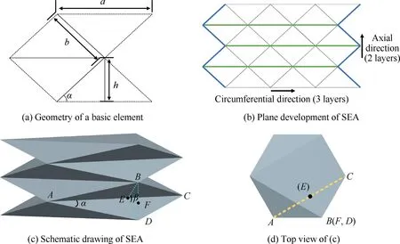
Fig. 2 Structural topology of SEAs.

Fig. 3 Experimental and analysis results of SEA.

Fig. 4 Soft Bendable Joint (SBJ).
By pressurizing a single bellow, such as B, the length difference between the bellows causes the SBJ to achieve a bending motion in the OXZ plane,as shown in Fig.4(b).Compared with three concentric blue arcs, it is seen that the deformed configurations of the bellows appeared to be constant curvature arcs after actuation. While Belongates after pressurization, Bcontracts to keep the system in balance, allowing us to make the assumption that the bellows bend in constant curvature arcs after pressurization, and the length of the arc across the center of two nylon plates (the red dashed line in Fig. 4(b)) remains constant with a value of l. R is the radius of curvature of the arc across the center of two nylon plates.
The pitch angles of the SBJ are defined as (θ, θ, θ, θ),respectively when the bellows (B, B, B, B) are pressurized by a chamber pressure (P, P, P, P). The SBJ can achieve a bending motion with yaw angle φ when two neighboring bellows are simultaneously pressurized, as shown in Fig. 4(c). The origin of the XYZcoordinate system is located at the center of the upper nylon plate, with Xand Ypointing to Band B, respectively, and Zis determined by the right-hand rule vertical to the nylon plates. The XYplane can be divided into four quadrants, and the yaw angle φ is the angle between the bending motion plane and X.The bellows that need to be pressurized are determined by the quadrant in which the bending plane falls. If the SBJ is expected to bend in quadrants 1 and 4,bellows Band Bwill be pressurized. Therefore, the pitch angle θ, yaw angle φ and radius of curvature R can be found as

2.4. Kinematic modeling
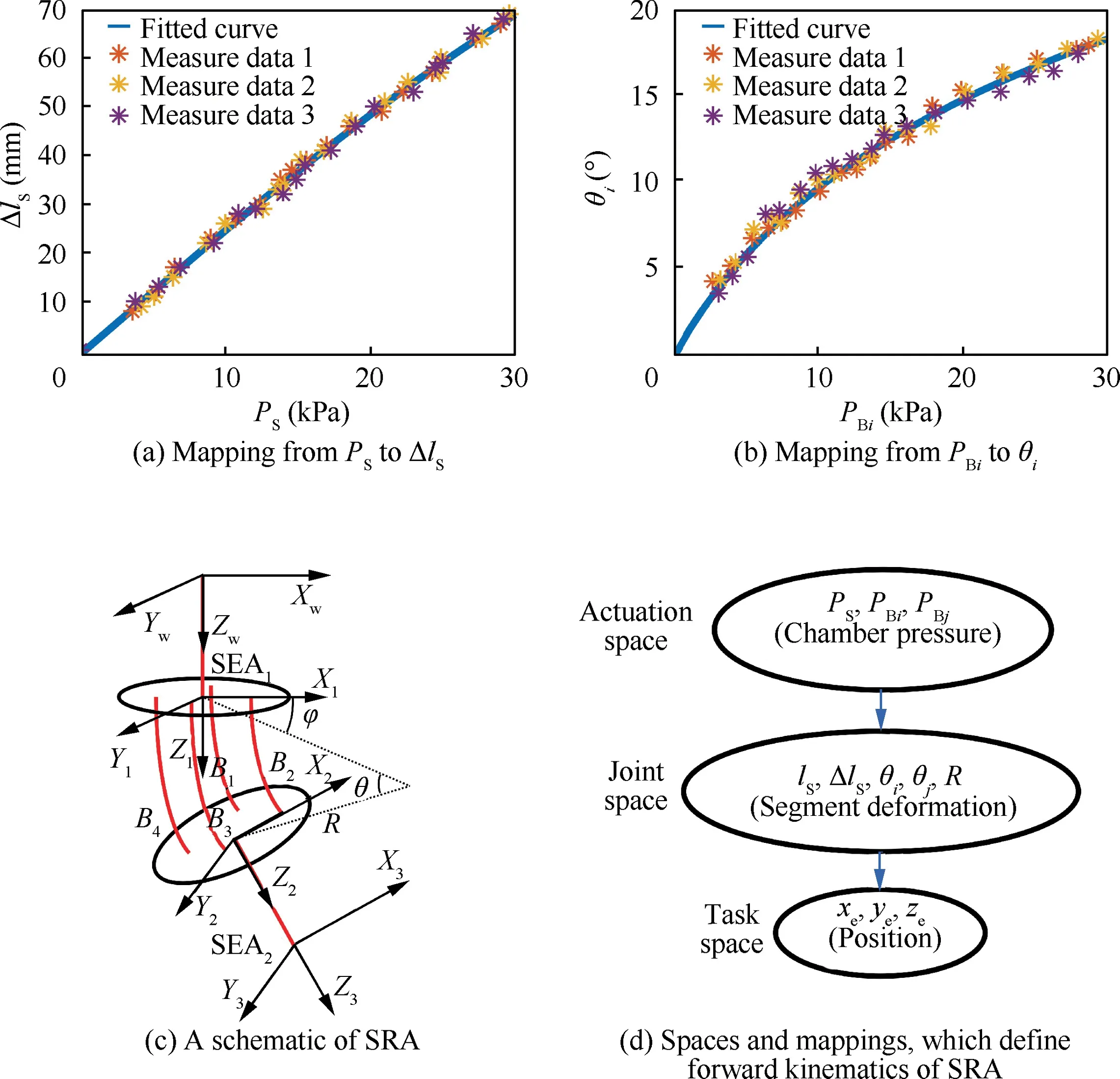
Fig. 5 Forward kinematics of SRA.
In this part,the forward kinematic model of the SRA using the Denavit-Hartenberg method (D-H method) is formulated, as shown in Fig. 5. XYZis described in part B. The origin of the XYZcoordinate system is located at the center of the lower nylon plate, with Xand Ypointing to Band B,respectively,and Zdetermined by the right-hand rule vertical to the nylon plates.The origin of the XYZcoordinate system is established by moving the XYZcoordinate system along the centerline of SEAto the initial SEA, with the origin of the XYZcoordinate system established similarly by moving the XYZcoordinate system along the centerline of SEAto the end of SEA. All coordinates mentioned below are unified with the world coordinate system XYZ.
The first step of the kinematic modeling is to describe the relationship between the position coordinates of the SRA’s end (x, y, z) (task space) and the deformation parameters(l, Δl, Δl, φ, θ, R) (joint space), where Δland Δlare the elongation of SEAand SEAafter pressurization, respectively;φ,θ and R are defined in part B,and lis defined in part A of this section. The relative displacements between XYZand XYZcan be obtained by performing a series of rotations and translations. Using the Denavit–Hartenberg method(D-H method), the transformation XYZ→XY-YZ→XYZ→XYZ→XYZcan be treated as the result of rotation and translation listed in Table 1, where each index matches a transformation matrix T:
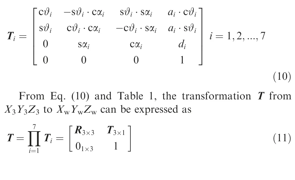

According to Eq.(12),the motion in the z-direction is coupled to the motion in the and y directions.This causes difficulties in the design of the control system. However, the closedloop control system described in the next section can resolve this problem.
As lis a constant and R can be calculated by Eq.(9)when θ is determined, there are three degrees of freedom in the task space (x, y, z) and four independent joint parameters (Δl,Δl,φ,θ).To establish a one-to-one correspondence relationship, the chambers of SEAand SEAare connected by a Tpipe to constrain Δl= Δl= Δldue to the same chamber pressure.φ and θ are substituted into Eq.(7)and Eq.(8)to calculate θand θ(i and j are determined by the quadrant in which the position coordinates of the end fall).Then,the joint parameters (Δl, Δl, φ, θ) are transformed to (Δl, θ, θ).
The second step is to obtain the mapping from the chamber pressures (P, P, P) (actuation space) to the deformations of each segment (Δl, θ, θ), where P, Pand Pare the chamber pressures in the SEA and bellows i and j,respectively.When the chamber pressure Pin the two SEAs was increased from 3 kPa to 30 kPa,the average elongation Δland average chamber pressure Pat each step were measured.By repeating the experiment three times, the relationship between Pand Δlcould be fitted by a Gaussian fitting, as shown in Fig. 5(a). The relationship between Pand θ(i = 1, 2, 3, 4) were obtained using the same method, as shown in Fig. 5(b).Finally, by the relationship curves, the transformation relationship from (P, P, P) (actuation space) to (x, y, z)(task space) via (l, Δl, θ, θ, R) (joint space) can be established,as shown in Fig.5(d).Using the kinematic model,determining how that chamber pressures (P, P, P) change the position coordinates of the SRA’s end (x, y, z) can be formulated.

Table 1 D-H parameter.
3. Closed-loop control
To autonomously control the position coordinates of the SRA’s end (x, y, z) to reach the destination coordinates(x, y, z), a closed-loop model-free control system is developed, as depicted in Fig. 6. The two chambers of SEAand SEAconnected by the T-pipe are defined as SEA.The control policy can be summarized as follows:
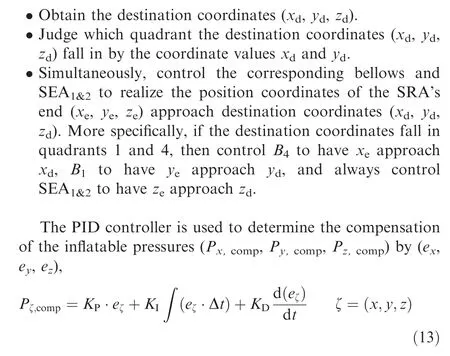
where e= ζ– ζ(ζ = x, y, z) are the coordinate deviations between(x,y,z)and(x,y,z);K,Kand Kare the coefficients of the proportional part, integral part and differential part in the PID controller, respectively; and Δt is the time interval between two iteration steps.
In Eq. (13), a large coordinate deviation ewill result in a large proportional gain K∙e, and then, there will be a large pressurization pressure compensation Pbetween two adjacent iteration steps.Thus,gas will flow quickly to decrease the coordinate deviations. As the coordinate deviations approach zero, the integral item and differential item come into play to eliminate steady-state deviations and avoid overshoot, respectively.

where Pare the output pressures of the proportional valves in previous iteration steps.
The initial output pressures(P,P,P)are set to 0 kPa. A vision sensor system will provide the real-time coordinates (x, y, z) as the feedback for the PID controller successively to calculate the compensation of the pressurization pressure of the current iteration steps.
We have developed an x-controller, a y-controller and a zcontroller in the control system to control the motion in xdirection, y-direction and z-direction, respectively. The controllers will work independently to eliminate the corresponding position error.For example,zhas reached z,while xis still increasing (decreasing) to reach x. At this moment, the coupled influence from the change in x-position will cause zto deviate from z, hence the z-controller will operate immediately to control zto reach zagain.
4. Experiment validation
To experimentally verify the SRA’s kinematic model and the closed-loop control system, an experimental platform was set up, as shown in Fig. 7. An SRA prototype was fixed to a grounded frame by means of threaded connection on the upper end of SEAand contained a small yellow ball on the end of the SRA, allowing the external camera system to localize its position. The experimental platform included a laptop (Y9000X, Lenovo, Inc., China) running the PID control algorithm and sending a control signal,an MCU (STMicroelectronics, Inc., Italy), five proportional valves (ITV2050-312L, SMC Inc., Japan), three pressure sensors (SPAN-P1R-Q4-PNLK-PNVBA-L1, Festo, Inc.,Germany), a gas compressor (OUTSTANDING, Inc.,China) supplying inflatable gas and several cameras(ORBIT, NOLOV, Inc., China) digitally capturing the motion of the SRA.
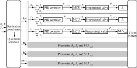
Fig. 6 Full block diagram of closed-loop control system.
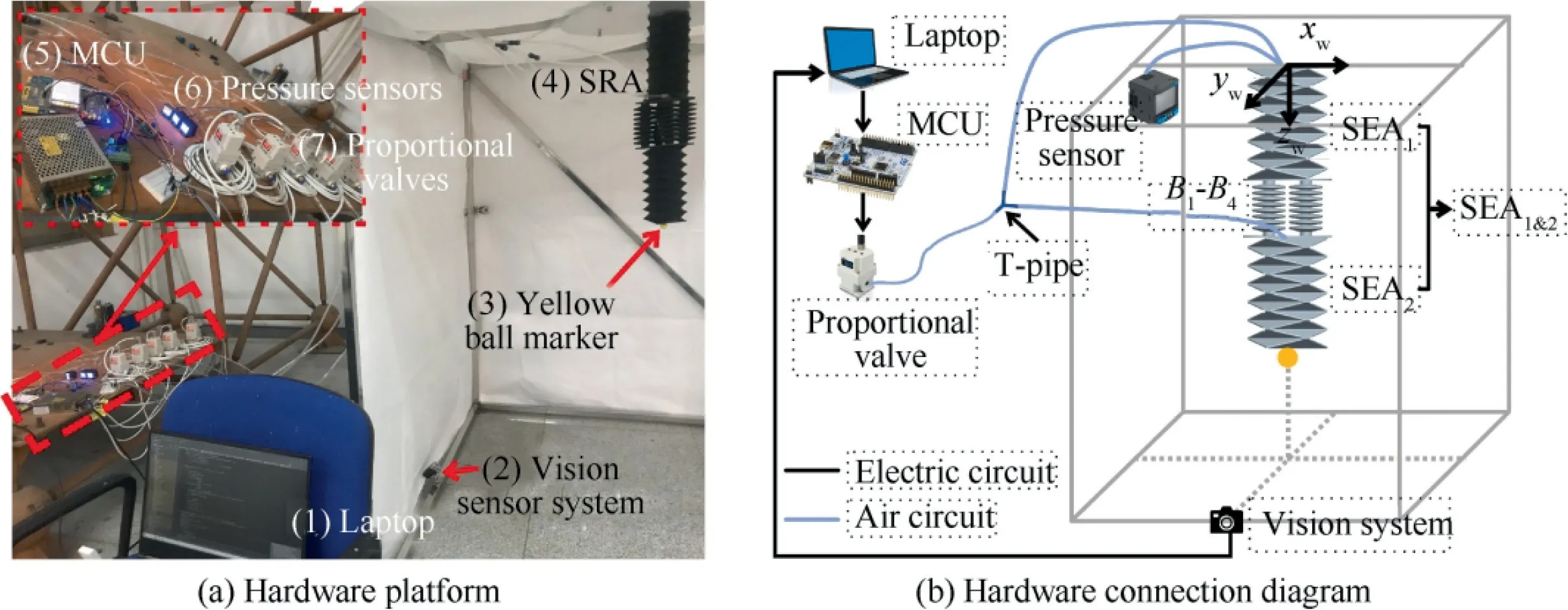
Fig. 7 Layout of experiment platform.
4.1. Kinematic model evaluation
To validate the kinematic model of the SRA, SEAand the bellows were actuated simultaneously to obtain the transformation relationship from (P, P, P) to (x, y, z). Because the bellows were installed circularly and only two neighboring bellows were pressurized at the same time,this experiment was carried out in the first quadrant corresponding to bellows Band B. As a metric of the goodness of the kinematic model,the predicted position coordinates (x, y, z)of the end were compared with the measured coordinates (x, y, z). Fig. 8 presents a comparison between the measured and predicted values of the coordinates. Path 1, in blue, correspond to Pincreasing uniformly from 5 kPa to 10 kPa, with Pand Pincreasing uniformly from 5 kPa to 20 kPa. Path 2, in green,correspond to Pincreasing uniformly from 5 kPa to 10 kPa, with Pand Pincreasing uniformly from 5 kPa to 20 kPa.Path 3,in red,correspond to P,Pand Pincreasing uniformly from 5 kPa to 20 kPa. The circle and asterisk values are the predicted and measured position coordinates,respectively.The variation trends of(x,y,z)and(x,y,z)show a high degree of similarity. The root mean square errors(RMSEs)in the x,y,and z positions are within the acceptable range with values of 7.32,3.30 and 4.65 mm,respectively.The results show that the derived kinematic model can finely describe the movement of the SRA.However,several predicted and measured values of the coordinates deviate significantly.The error mainly comes from the constant curvature assumption, strongly nonlinear model and data fitting in Fig. 5(a)and (b). Because the error is hard to eliminate, the kinematic model has difficulty applying precise SRA position control.
4.2. Closed-loop end-position control
To validate the performance of the closed-loop model-free control system, an experiment that controlled the SRA’s end position was carried out.The end moved from the initial coordinates (0, 0, 604) to the programmed destination coordinates(110, 120, 670). The experimental results are shown in Fig. 9.Fig. 9(a) and 9(b) shows the movement process in which the SRA’s end approaches the destination.
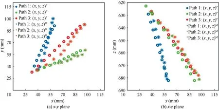
Fig. 8 Experimental validation of proposed kinematics model.
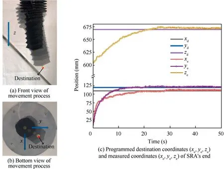
Fig. 9 Experimental evaluations of closed-loop position control system on SRA prototype.
According to Fig. 9(c), zapproached zslowly due to the large SEA chamber volume,while xand yresponded quickly in the first 4 s because the pressures in the bellows rapidly increased. After reaching the destination coordinates (x, y,z), (x, y, z) tended to be in a stable state. As described before, the motion in the z-direction is coupled to the motion in the x and y directions. Therefore, the controller in the zposition tried to track zat each iteration step, and the controllers in the x and y positions will also adjust the chambers’pressures to track xand y, respectively. This was why ytended to be stable after reaching y, even though zwas still increasing. By increasing the proportional coefficient Kin the z-controller, the response speed of zcould be greatly improved, but it would cause a small oscillation.
The state in the last 10 s during this experiment is defined as the steady state of the SRA. The RMSEs for the x ,y and z positions of the steady state were 1.13, 2.35 and 2.65 mm,respectively, which demonstrates that the proposed closedloop control system is reliable in end-position control of the SRA within acceptable error. The errors of the end position of the SEAs can be compensated by the design of a adaptable gripper.
4.3. Trajectory tracking
Furthermore, we performed an experiment to explore the trajectory tracking ability using the closed-loop position control system and characterized the SRA’s location precision. The trajectory tracking capabilities were tested by charting the movement path of a planar equilateral triangle, whose side length was 120 mm and had a speed of 6 mm/s. The experimental trajectories and the movement path simulated in MATLAB were compared, as shown in Fig. 10.
The RMSEs for the x,y and z positions were 5.08,3.28 and 4.03 mm, respectively. The position errors of the trajectory tracking experiment were larger than those in part B because of the hysteresis caused by continuously changing destination coordinates. As shown in Fig. 10(c), at the beginning and end of the experiment, the dynamic responses in the x and y positions exhibit a small oscillation due to the low stiffness of the bellows under low pressurization pressure. Because of the coupled influence of the movement in the x and y directions, a large overshoot phenomenon appeared in the zposition, which was subsequently corrected by the zcontroller. The vast majority of the measured trajectories in the red curves coincide well with the programmed trajectories in the blue curves, showing an acceptable trajectory tracking ability of the closed-loop control system.
4.4. Cyclic movement experiment
The reliability of the SRA closed-loop control system was experimentally validated by cyclic movement experiments.The SRA’s end was controlled by moving from the initial coordinates (0, 0, 604) to the destination coordinates (110, 120,670) 300 times repeatedly, and the RMSEs of the steady state was characterized, as shown in Fig. 11.
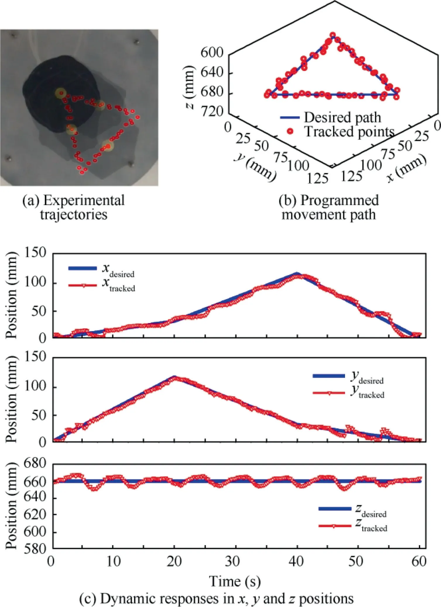
Fig. 10 Experimental evaluations of trajectory tracking ability of control system on SRA prototype.
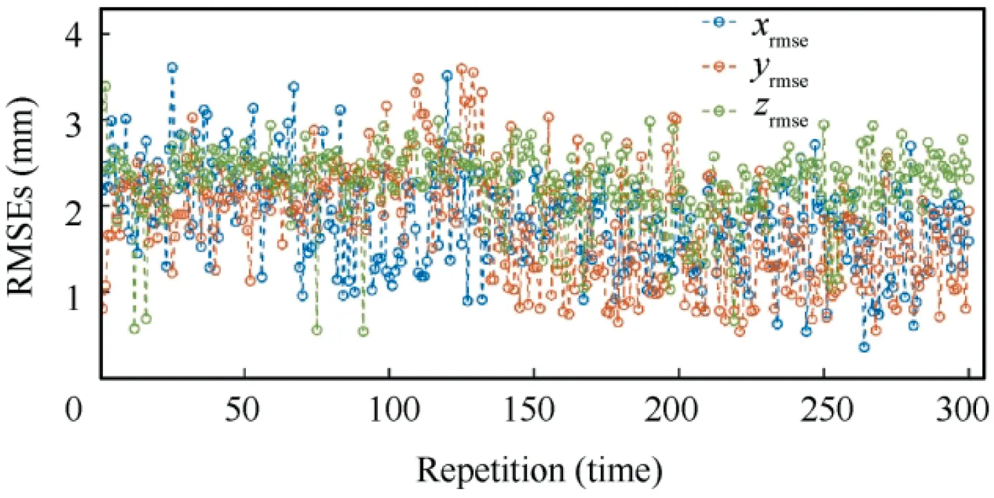
Fig. 11 RMSEs of steady state in x ,y and z positions plotted over 300 repetitions.
The data points are mainly distributed at less than 3 mm during the experiment with several exceptions. Because the SRA is a complex and nonlinear system, there will inevitably be fluctuations in the end-position control throughout the experiment. As the number of experiments increased, the RMSEs did not constantly increase. This demonstrates that the end-position control of the SRA remained reliable even after long-term repeated operations. The reason is that the proposed closed-loop control system is not based on a kinematic model; thus, the change in mechanical properties of rubber-like materials caused by the Mullins effect, plastic deformation, etc. will not affect the long-term performance of the control system.
5. Conclusions
A novel SRA inspired by the human arm composed of two soft extensible arm (SEAs) and a soft bendable joint (SBJ) is presented.The SRA can achieve combined bending and stretching movement. Based on the assumption of constant curvatures,the forward kinematic model was derived using the D-H method. To avoid the failure caused by mechanical behavior changes in rubber-like materials, a model-free, closed-loop and vision-based control system was developed. The control system can drive the SRA to reach the destination point within acceptable error,where the steady-state RMSEs in the x,y and z positions were 1.13, 2.35 and 2.65 mm, respectively. Moreover, the control system demonstrated good tracking ability,where the RMSEs for the x,y and z positions from the trajectory tracking experiment were 5.08,3.28 and 4.03 mm,respectively. Furthermore, the end-position of the SRA remained highly reliable after a long-term task, with the RMSEs in the x, y, and z positions over 300 repetitions mainly distributed at less than 3 mm,which is significant for promoting reliability in a soft robot. Future work includes the design of a soft end effector and investigating a control method to evade obstacles.
The authors declare that they have no known competing financial interests or personal relationships that could have appeared to influence the work reported in this paper.
This work was co-supported by the National Natural Science Foundation of China (No. 91748209 and 11402229), Natural Science Foundation of Zhejiang Province (No.LY17A020003), and the Fundamental Research Funds for the Central Universities (No. 2018QNA4054 and 2019QNA4057).
 Chinese Journal of Aeronautics2022年7期
- Chinese Journal of Aeronautics的其它文章
- An online data driven actor-critic-disturbance guidance law for missile-target interception with input constraints
- Study on excitation force characteristics in a coupled shaker-structure system considering structure modes coupling
- Smooth free-cycle dynamic soaring in unspecified shear wind via quadratic programming
- Active and passive compliant force control of ultrasonic surface rolling process on a curved surface
- High dynamic output feedback robust control of hydraulic flight motion simulator using a novel cascaded extended state observer
- Composite impact vector control based on Apollo descent guidance
