Wide-range model predictive control for aero-engine transient state
Bing YU, Zhouyng LI, Hongwei KE, Tinhong ZHANG
a Jiangsu Province Key Laboratory of Aerospace Power System, Nanjing University of Aeronautics and Astronautics,Nanjing 210016, China
b Institute of Aeronautical Control System, Wuxi 214063, China
KEYWORDS Flight envelopes;Model predictive control;Predictive control systems;Transients;Turbines
Abstract To perform transient state control of an aero-engine, a structure that combines linear controller and min–max selector is widely adopted, which is inherently conservative and therefore limits the fulfillment of the engine potential.Model predictive control is a new control method that has vast application prospects in the field of aero-engine control. Therefore, this paper proposes a wide-range model predictive controller that can control the engine over a wide range within the flight envelope. This paper first introduces the engine parameters and the model prediction algorithm used by the controller. Then a wide-range model prediction controller with a three-layer nested structure is presented. These three layers of the structure are univariate controller, nominal point controller, and wide-range controller from inside to outside. Finally, by analyzing and verifying the effectiveness of the univariate controller for small-range variations and the wide-range model predictive controller for large-range parameter variations, it is demonstrated that the controller can schedule the controller’s output based on inlet altitude, Mach number, and lowpressure shaft corrected speed, and ensure that the limits are not exceeded. It is concluded that the designed wide-range model predictive controller has good dynamic effect and safety.
1. Introduction
Aero-engines are highly nonlinear and complex thermodynamic mechanical systems, which work in a tough environment with a wide flight envelop. How to gain the full potential of aero-engines while ensuring its safe operation has been a hot spot for a long time. As early as 1999, Austin Spang and Brown pointed out that aero-engines should operate at the performance envelope to reach their full potential.Since then, each breakthrough to the original performance envelope is an improvement in the performance of aeroengine.
To describe the aero-engine’s operation, two typical working states,transition state and steady state,are defined.Steadystate control is used to keep the physical system near the desired operating conditions over time. Transient control is used to move the system’s steady-state operating condition from one to another within a given time period and within prescribed bounds.It has been pointed out that the design cycle of the transition state controller occupies nearly three quarters of the total design cycle of the controller.So,the development of a transition state controller is more important and difficult than that of a steady-state controller.
The transition state controller has two main objectives.One is to ensure that the parameters of the engine do not exceed the limit during the transition state. The other is to transfer the engine from a steady-state point to another as soon as possible.Therefore, it is of great significance to research and optimize engine transition state control to improve engine performance and expand its life.
At present, to coordinate thrust management and constraint management, the structure which combines the linear controller and min–max selector is widely adopted by aeroengine control.
Trepresents the inlet temperature of the aero-engine, Prepresents the inlet pressure of combustor. As shown in Fig. 1, the min–max selector ensures that the engine works within a limit range by switching control signal according to various constraints. min–max selector structure has been widely adopted in commercial aircraft engines for its clear control logic and easy implementation, such as GE90, PW2000,etc.However, in recent years, the higher performance requirements of aircraft engines bring great challenges for operating near the material’s physical limit. It has been found that the traditional structure is inherently conservative.And such kind of conservatism restricts the exertion of the potential of the aero-engine.For instance,in an urgent case that requires a rapid increase of thrust,the engine might be a failure to meet the demand when using the traditional limit management,which may even cause a terrible disaster.In the Sioux City disaster of 1989, for example, the conservative design of the engine control system prevented it from achieving a faster dynamic response in an emergency, which ultimately led to the crash of United Flight 232.
To solve the conservative problem of the traditional structure, researchers put forward various improvement methods.For example,nonlinear controllers,such as sliding-model controland Active Disturbance Rejection Control(ADRC),are used to replace linear controllers to improve controller’s performance. Meanwhile, nonlinear optimization methods without min–max selection structure such as the SQP method,FSQP method,and the genetic algorithmcan be used for improvement.
Model Predictive Control (MPC) has originated in the industry as a real-time computer control algorithm to solve linear multivariable problems that have constraints and time delays.It has a great prospect in aero-engine control due to its advantages in balancing constraint management and thrust management.With the continuous improvement of the onboard computer processors and the development of relevant MPC optimization algorithms in recent years, the MPC algorithm’s advantage has become increasingly prominent.In 2011, Chang and Yang addressed robust constrained MPC for a class of nonlinear systems with structured timevarying uncertainties. In 2020 Cai et al. proposed a virtual target guidance based distributed model predictive control scheme for formation control of multiple unmanned aerial vehicles.
In recent years,the research of the MPC control algorithm applied in aero-engine has also been widely reported. For example, in 2004, a multivariable MPC controller designed by Brunell et al.was verified on the high bypass ratio turbofan model.In 2011,Akpan and Hassapis designed an MPC controller for the F-16 engine, which obtained satisfactory results.In 2014, Du et al. designed an MPC controller for a commercial turbofan engine.In 2020,Wang et al.proposed a study of nonlinear model predictive control of turboshaft engines based on dual-engine torque matchingand so on.
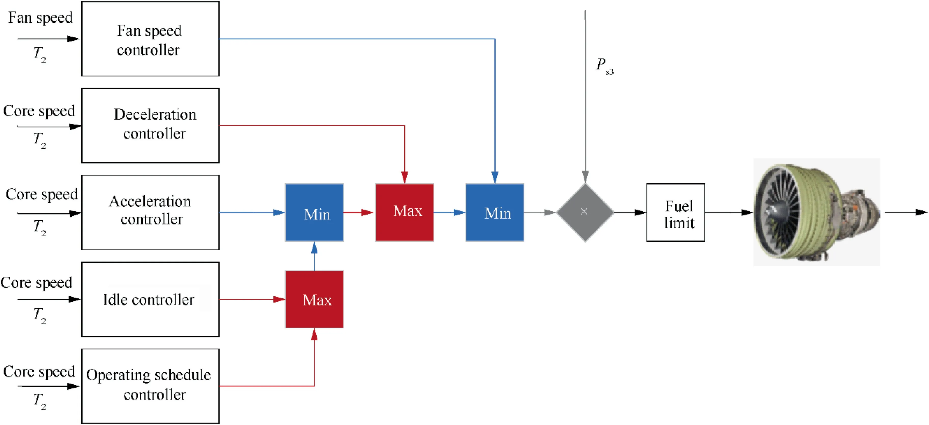
Fig. 1 Structure of classic controller.
In this paper,a model predictive controller for high bypass ratio, two spools, and unmixed turbofan is presented, which can run in a wide flight envelope, and its effectiveness and safety are verified by simulation. The paper is organized as follows. Section 2 gives a brief introduction about the control object and the model prediction algorithm used by the controller. The three-layer construction of the wide-range model predictive controller is described in Section 3. In Section 4,first, the effectiveness of the univariate controller is verified,and then the reason why univariate controller cannot be used when the parameters vary widely is explained. Finally, the effectiveness and dynamic performance of the wide-range controller are verified. Section 5 concludes the paper.
2. Model prediction algorithm
2.1. Aero-engine
The control object selected in this paper is a high-bypass-ratio two-spool unmixed turbofan, as shown in Fig. 2. The main components of the engine are an inlet, a fan, a Low-Pressure Compressor (LPC), a High-Pressure Compressor (HPC), an outer nozzle, a combustor, a High-Pressure Turbine (HPT),a Low-Pressure Turbine (LPT), and an inner nozzle. The nozzle has an area of this type of engine that is not adjustable.Both inner and outer bypass outlet use a convergent nozzle.The definition of each section is shown in Table 1. The engine parameters of the design point selected in this paper are shown in Table 2.
2.2. Linear predictive model
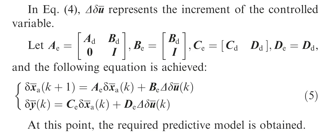
Linearization methods can be used to obtain a linear state-space equation of the engine at a certain steady-state point:
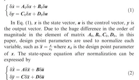
For simulation purpose, the equations must be discretized.The discrete-time state-space equation can be expressed by
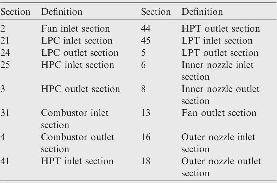
Table 1 Definition of each section of turbofan engine.

Table 2 Parameters of design point.
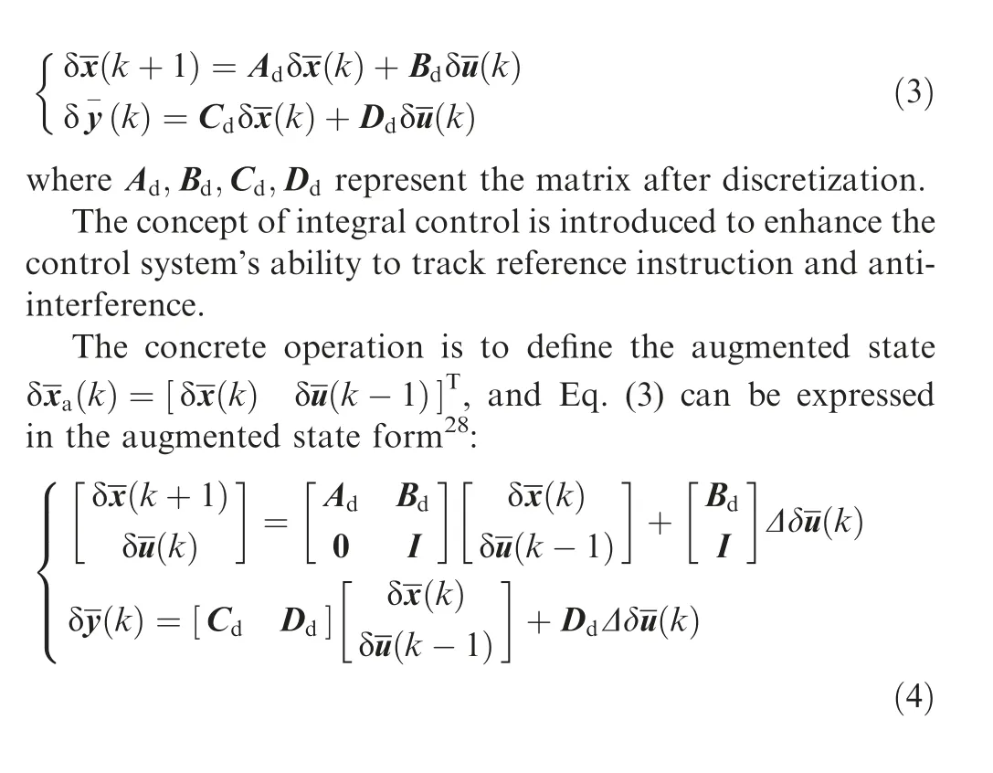

Fig. 2 Schematic diagram of turbofan engine.
2.3. Performance indicators and reference trajectories
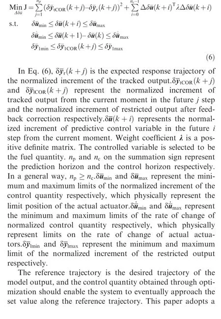
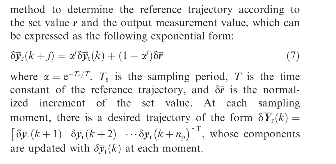
For the turbofan engine,the determination of the performance indicators in the algorithm should be combined with the control requirements of the actual engine. In this paper, the control goal of the aero-engine controller is to adjust the rotational speed of the low-pressure shaft to the expected speed rapidly and ensure that the relevant parameters do not exceed their limit conditions during the whole process. For a better explanation of the relationship between the control goal and restricted target, the engine output is divided into tracked output yand restricted output y.And then they are calculated respectively. The performance indicators can be defined as the deviation between the predicted output of the engine tracked output and the designed engine response trajectory value.Besides, the incremental control change is also taken as one of the performance indicators. Finally, engine performance indicators are as follows:
2.4. Feedback correction
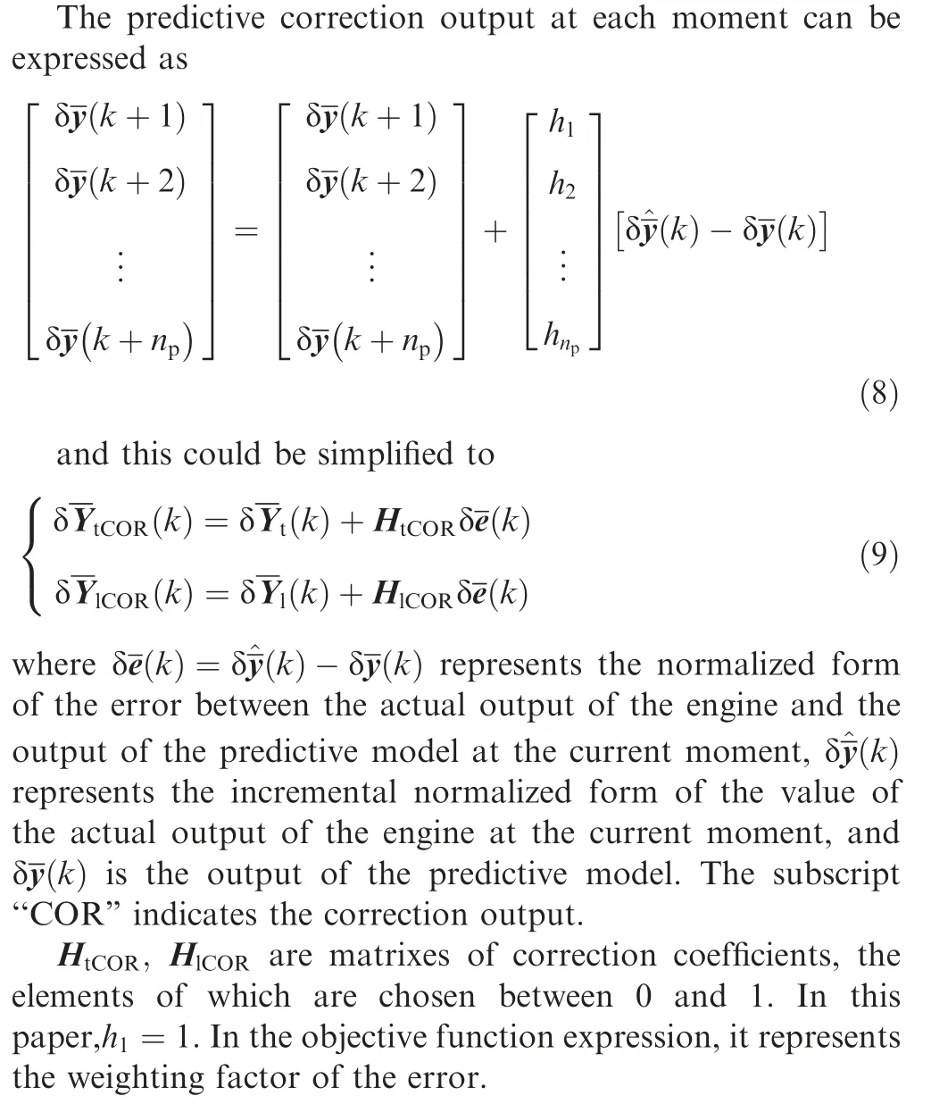
The fact that the chosen predictive model is a linearized model near a certain steady-state point leads to a situation where the model loses its match in the actual control process.To address this problem, the feedback correction of the output of the predictive model is needed. The methods of feedback correction are diverse.In this paper, the method of correcting the predictive output based on the error between the actual output and the output of the predictive model is used.
2.5. Algorithmic derivation
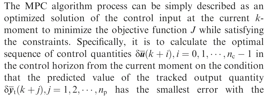
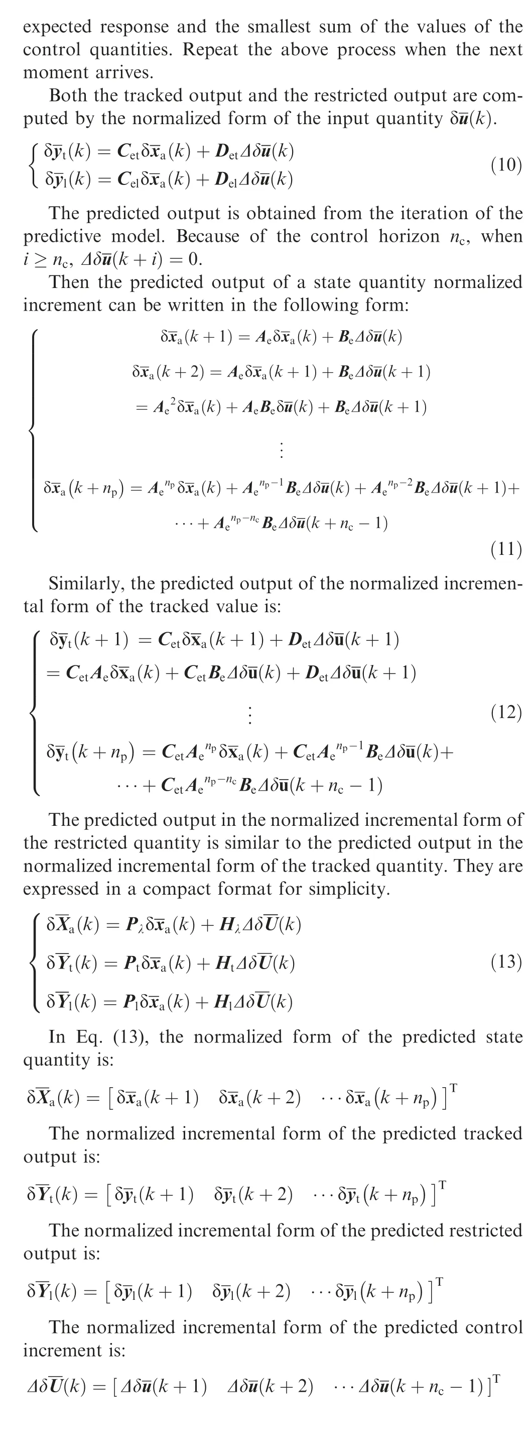
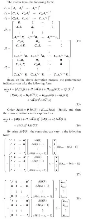
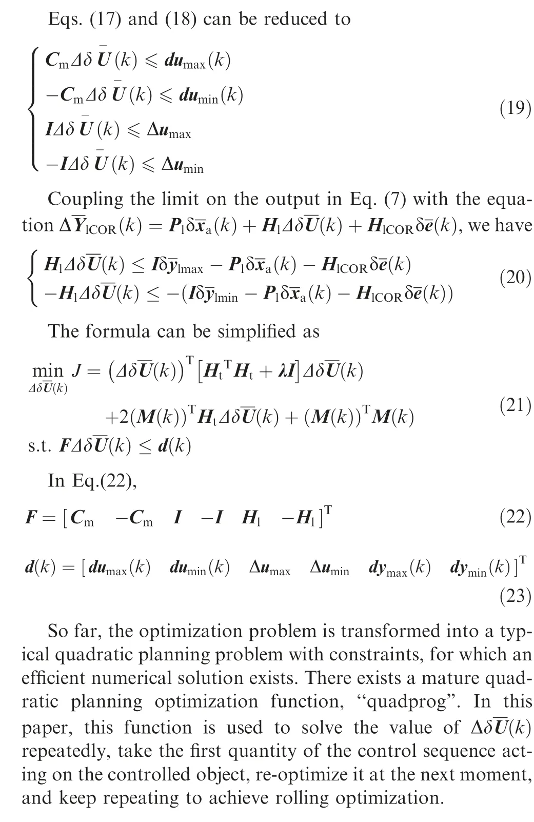
3. Design of a wide-range MPC controller
The scheduling scheme for the wide-range controller is a twostep process,the first step utilizing the speed scheduling scheme to calculate the output of the three nominal point controllers.The second step utilizes the altitude and Mach number scheduling scheme to achieve control of the wide flight envelope from 80%to 110%of the corrected speed range.The process is illustrated in Fig. 3.
The entire controller is a three-layer nested combination.The bottom level controller is a univariate controller that controls the engine state near the corrected speed point. In particular, in this paper, the concern is the adjustment range of 80%-110% of the corrected speed, so a group of four controllers was chosen to achieve a wide range of speed control scheduling at certain nominal points through a speed scheduling scheme; The second layer of controllers is the nominal point controller which is capable of controlling the engine state in the vicinity of the height-Mach number nominal point determined by the control area. The number of controllers in this layer is in groups of three, and the scheduling between the different nominal controllers is achieved through a designed height-Mach number scheduling scheme. The top controller is designed as a wide-range MPC controller. It is capable of determining the engine control quantity based on the inlet height, inlet Mach number, and current engine low-pressure shaft corrected speed, and is capable of controlling the engine working in the 80%–110% corrected rotational speed range.
3.1. Univariate model predictive controller
The block diagram of the closed-loop system under the action of a single-variable controller is shown in Fig. 4.
Based on the derivation in Section 2,the optimization problem turns into a typical quadratic planning problem with constraints. The univariate model predictive controller is written based on the algorithm in Section 2. From the algorithm, it is known that du(k ),du(k ),dy(k ),dy(k ),M(k ) are related to the current or previous moment’s variable value and therefore must be updated online. Variables like F,Δu,Δuwhich do not vary with time can be calculated offline in advance, thus reducing the number of online calculations.
3.2. Nominal point controller
A single point controller has the problem of not being able to meet the control requirements over the full flight envelope of the engine. In this paper, switched system is used to replace a single point controller.Switched systems are a type of hybrid system containing a family of subsystems and a switching signal. Designing the controller independently at different points and calling the different controllers utilizing scheduling is an effective way to extend the range of controller applications. In this paper, to extend the control range, we use the idea of sectional control to design the controller for a wide speed range from 80% to 110%. With 10% as an interval,and based on the 80% corrected rotational speed controller,we design the controller for the points of 90%, 100%, and 110% of the rotational speed. The detailed architecture is shown in Fig. 5.
When scheduling, the current corrected speed is used as the scheduling quantity. The goal of scheduling is that when switching from one controller to another, the output variables of the controllers should change continuously. The following is an example of the switching rule adopted in this paper. For an operating point whose speed lies between 80%–90% corrected speed, the final output value of the controller is the value after interpolation of the 80% controller and 90% controller output values. The formula is shown as

where Wrepresents fuel quantity; Nrepresents low pressure shaft speed.
What can be seen in Eq.(24)is that when the speed is gradually increased from 80%to 90%,the change in control quantity is smoothly switched between the outputs of the two controllers, which satisfies the proposed requirement.
3.3. Wide-range controller
The model predictive controller in Section 3.1 is based on a linearized model of an aircraft engine at a certain operating point, which has been extended in Section 3.2 to a wide rotational speed range at a fixed altitude and Mach number and will be extended in this section to a wide flight range.
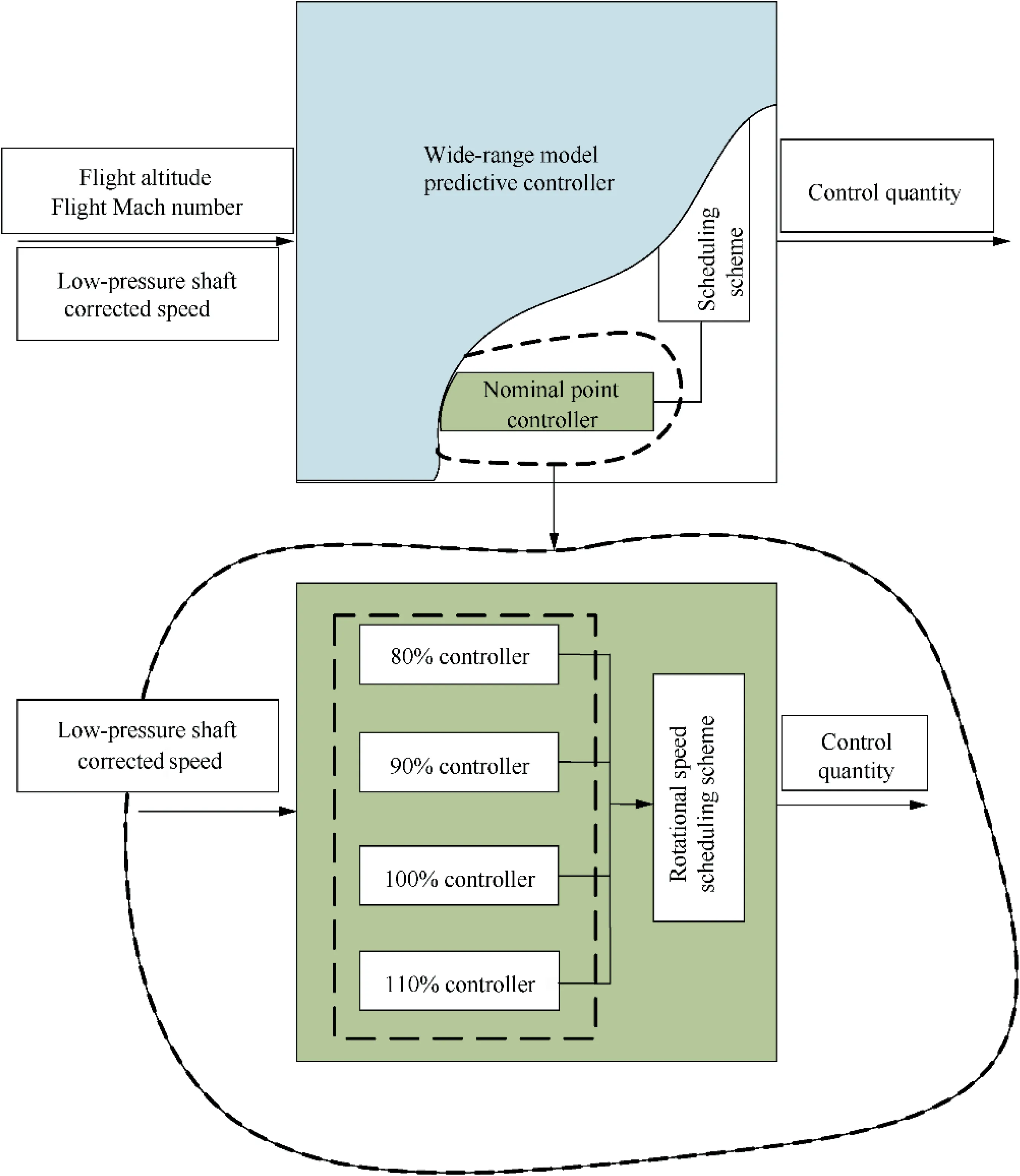
Fig. 3 Structure of wide-range controller.

Fig. 4 Block diagram of closed-loop system controlled by univariate model predictive controller.
3.3.1. Selection of nominal points
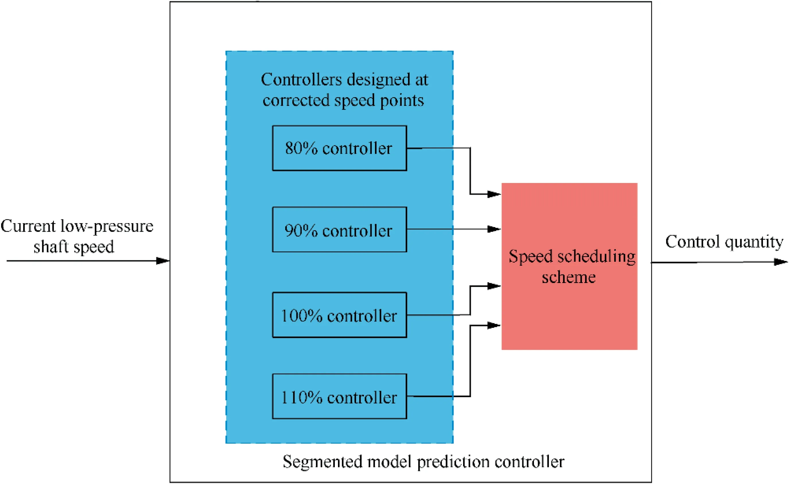
Fig. 5 Block diagram of sectional controller.
The principle of dividing multiple regions of the flight envelope can be summarized as follows: the differences between the state-space models should be as small as possible between the flight points grouped in the same region. This allows the controller based on the nominal point design to perform the desired control function. The nozzle and inlet channel area of the control object in this paper is not adjustable, and for a certain steady-state operating point, under certain control laws,when the fuel supply is determined,its state can be determined by the flight altitude and flight Mach number.Since the altitude and Mach number can be transformed into a function of the inlet total temperature and total pressure,the inlet total temperature and total pressure can thus be used to reflect the differences in space models of different flight point states. A definition of the generalized distance Dis introduced and used as an evaluation criterion to divide the flight envelope.

where P,Trepresent the total inlet pressure and temperature at the current point respectively; P,Trepresent the total inlet pressure and temperature at the nominal point respectively; Drepresents the difference between the total inlet temperature and pressure of the model at current flight points and the total inlet temperature and pressure of the model at the nominal point, and the value reflects the difference in performance between the current engine model and the nominal point engine model.ε reflects the degree of consistency of the points in the region. The smaller its value is, the better the consistency of the model for each point in the region is, and vice versa. When the generalized distance of a state point within the flight envelope satisfies the Eq.(25),the point can be partitioned within a subregion represented by the nominal point.
Since the actual flight envelope is too wide,to illustrate the division method of this paper, a control area is selected as an example for the division operation.The selected area is shown in Fig. 6, where H represents height,Ma represents Mach number.
The blue area in Fig. 6 is the selected control area. For the consideration of similarity,the shape of the control region chosen in this paper is consistent with the shape of the flight envelope, and the range becomes smaller.
The value of ε is first determined using the trial-and-error method, with the rule that the value is chosen to be as large as possible, provided the control effect is satisfactory. By increasing ε, the number of nominal points can be reduced,and thus the number of controllers can be reduced. Fig. 7 shows the division of the control area when different ε are selected for the same nominal point.
In order to evaluate the reasonableness of the area division,it is necessary to use the nominal point controller to verify the control of each point in the area.In order to reduce the workload,the point farthest from the nominal point is chosen as the verification point. In this case, the corner point of the red region, which can reflect the maximum error case, is chosen.The control effect is shown in Fig. 8.
The final choice of ε is 0.10,taking into account the division range and the degree of mismatch.
Then the Queen pondered the whole night over all the names she had ever heard, and sent a messenger to scour6 the land, and to pick up far and near any names he could come across
Then select the number of nominal points.The selection of the number of nominal points needs to be specific to the value of ε. As can be observed from the area divided in Fig. 8 the control area should require three nominal points.
After determining the initial parameters,this paper uses the K-means cluster analysis methodto divide the regions.
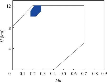
Fig. 6 Control area.
For the control object in this paper, a vector consisting of random flight altitude and flight Mach number is first used as a data object. An initial clustering center is randomly selected from the data object. After that, the generalized distance of the remaining data objects from the clustering center is calculated,and then these data objects are classified according to their generalized distance. The value of the new cluster center is calculated from the average value of each cluster.The above process is repeated until the change of cluster center satisfies the squared sum difference less than a specific value, or the number of iterations satisfies the requirement. The specific requirements can be indicated by
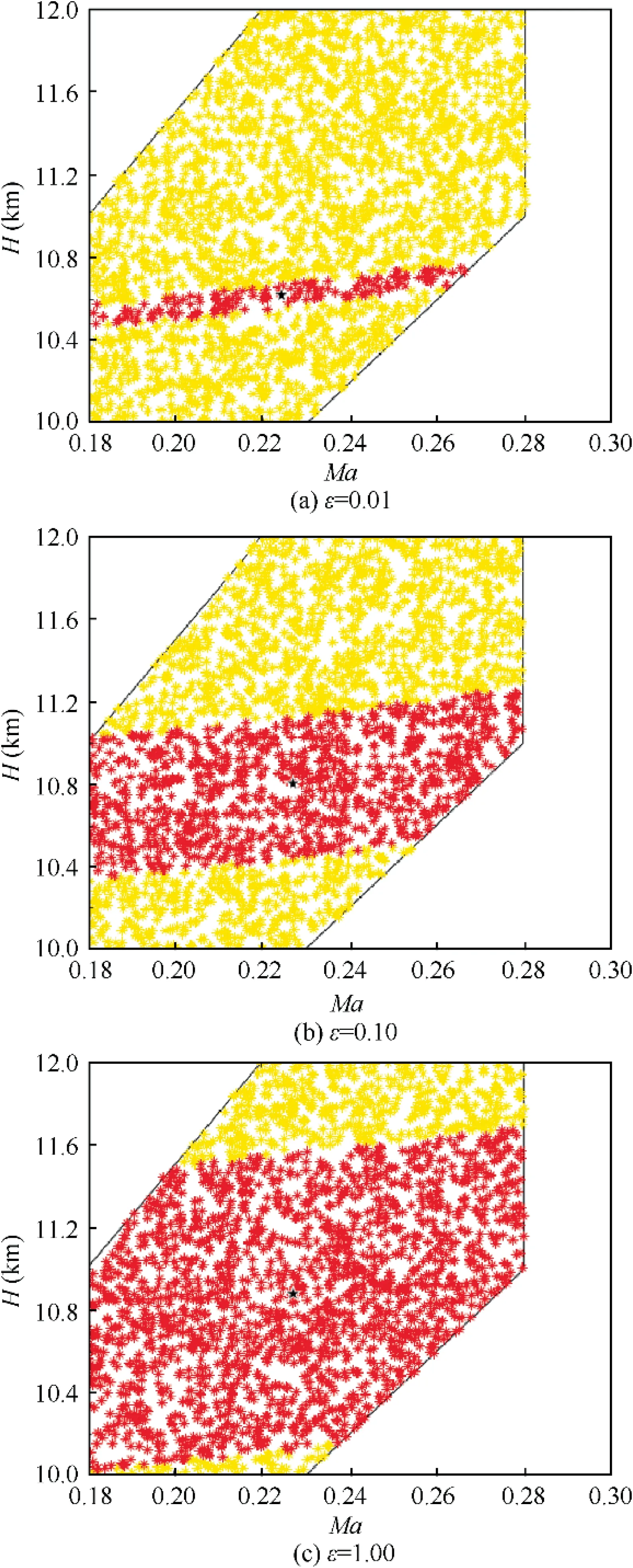
Fig. 7 Division of control areas under different ε.

where x,y represent the coordinates of the cluster center, the subscript ‘‘new”, ‘‘old” represent the new cluster center and the old cluster center respectively, and o is the user-defined loop end condition.
The control region was partitioned by the clustering method using a parameter of o=1×10and a maximum number of 2000 iterations. The final results obtained are shown in Fig. 9.
As can be seen,the control region is eventually divided into three parts,denoted by blue,red,and green.Its clustering center, the nominal point, is represented by a black pentagram.The specific coordinate values are shown in Table 3.
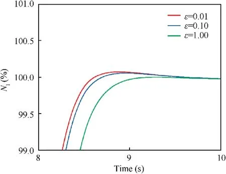
Fig. 8 System response at boundary points with different ε values.
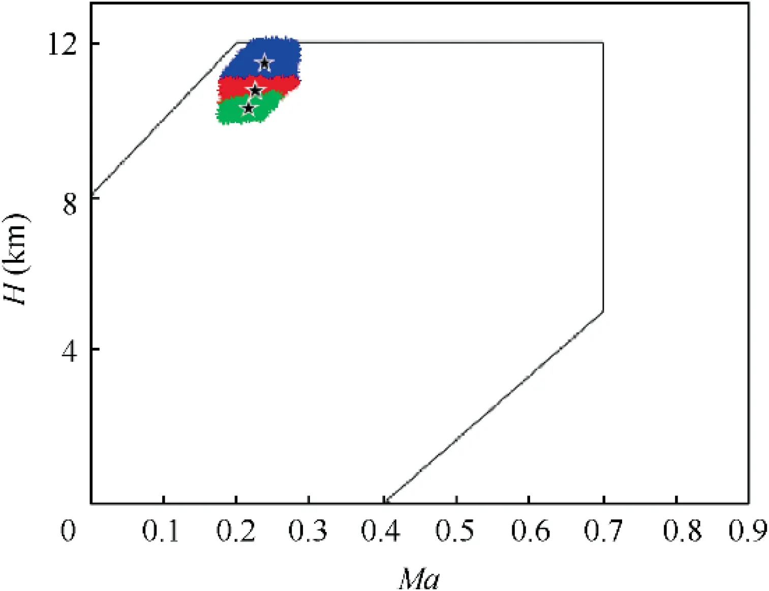
Fig. 9 Results of classification of control areas.

Table 3 Coordinate values of nominal points.
3.3.2. Altitude-Mach number scheduling scheme design
To avoid the problem of abrupt changes in control quantity caused by zone switching, interpolation with the outputs of neighboring controllers is required at different altitudes and Mach numbers regions. Because the altitude and Mach number are a function of the inlet temperature and total pressure,the outputs of adjacent controllers can be interpolated and selected by the inlet temperature and total pressure.To reduce the number of variables, the total inlet temperature and pressure are transformed into a ‘‘distance” definition using a generalized distance definition.The interpolation of the controller output is selected according to the‘‘distance”between the current state point and the adjacent nominal point.
To clarify the altitude-Mach number scheduling scheme used in this paper, an engine state point at Mach number 0.23,11000 m altitude,and 85%of the low-pressure rotor corrected speed is taken as an example. A diagram of the specific scheme is shown in Fig. 10.
Since the state point, with Mach number 0.23 and an altitude of 11000 m, is located between nominal points 2 and 3,its ‘‘distance” between the two adjacent nominal points can be calculated by using the formula for the generalized distance.It is defined as follows:

where P,Trepresent the total inlet pressure and temperature at the No. n nominal point. It should be noted that the red and green lines in Fig.10 are not a specific size representation of the generalized distance but are meant to visually illustrate the size.
The value of Dcharacterizes the proximity of the selected state point to the nominal point No.n.The smaller the value of Dis, the closer the state of the selected state point is to the nominal point No.n. The control quantity corresponding to the selected state point can be expressed as

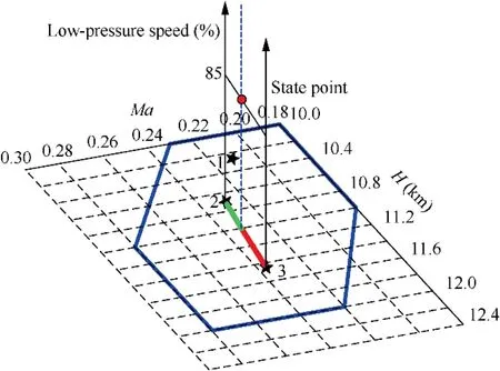
Fig.10 Schematic diagram of altitude-Mach number scheduling scheme.
Analyzing Eq. (28), we know that the closer the current state point is to nominal point No.2, the smaller the value of Dwill be, and the control quantity Wat nominal point No.2 will dominate the control quantity in the final output.Conversely, the closer the current state point is to nominal point No.3,the closer the final output of the control is to nominal point No.3 controller output W.And the value of Wtransits smoothly between Wand Wwhen the state point switches between the two nominal points. It should be noted that the above is just an example of this scheduling scheme and does not mean that it is only applicable to the process of switching between nominal point No.2 and nominal point No.3.It applies to switching between any two nominal points.
4. Simulation and analyses
4.1. Simulation validation of univariate model predictive controller
For the turbofan engine model in Section 2.1, the tracked quantity is chosen to be low-pressure shaft speed N, the control quantity is the fuel flow W,the state quantity is chosen to be high and low-pressure shaft speed N,N, and the output quantity is chosen to be low-pressure shaft speed N,the surge margin of the fan SM, the turbine inlet temperature Tand gas-oil ratio FAR4.
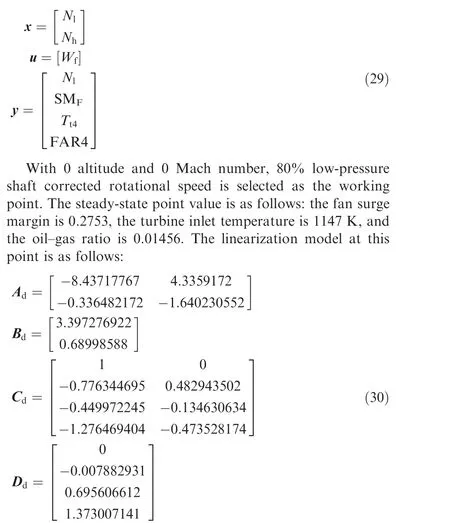


To verify the control effect of the model predictive controller in this paper over a small range of rotational speed variations,the response of the system when the parameters are constrained and unconstrained is observed.The specific results are shown in Fig. 11.
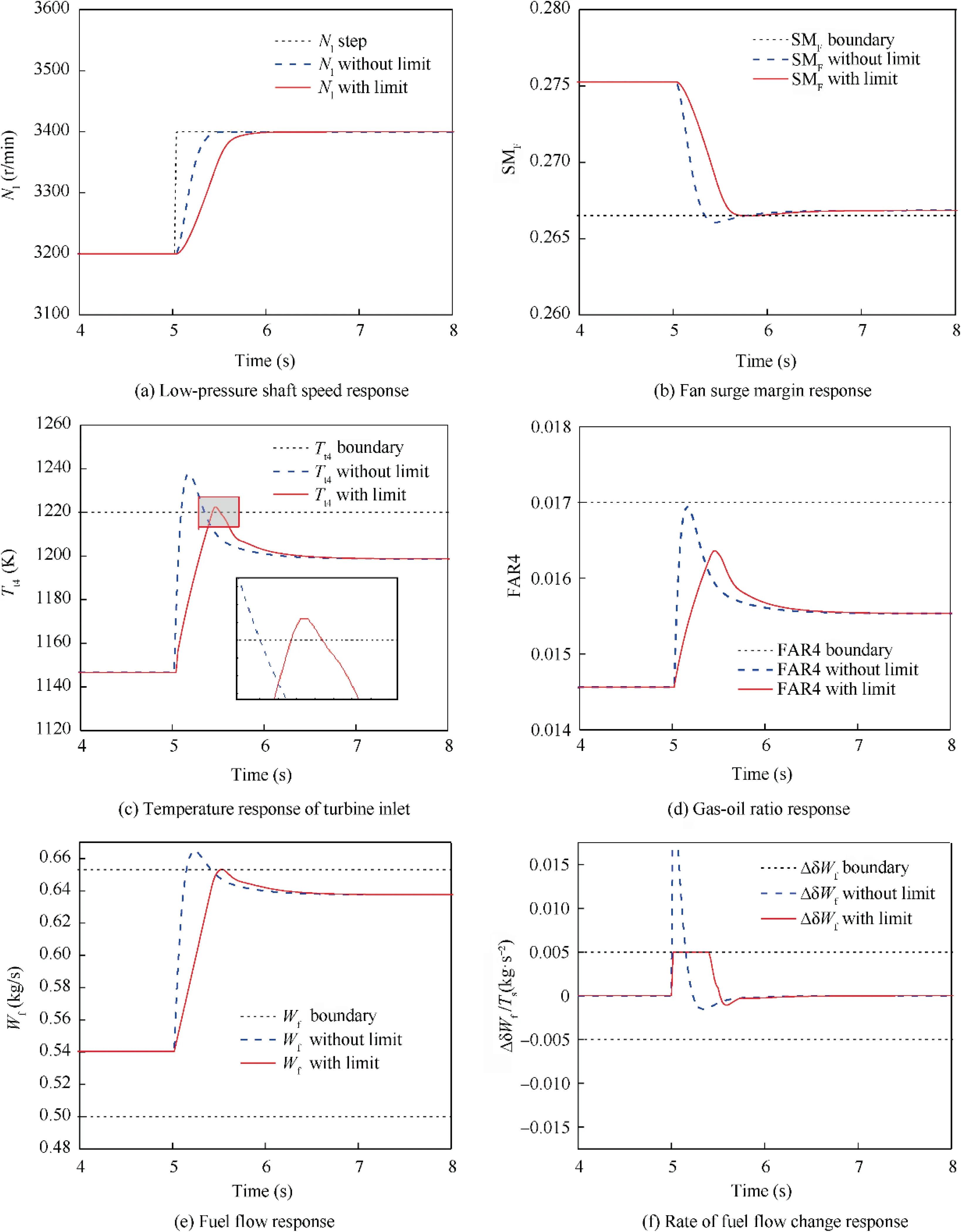
Fig. 11 Univariate model predictive controller response comparison plots before and after restriction addition.
From Fig. 11(a), it can be seen that when a small step occurs in the low-pressure shaft rotational speed, the response of the system in the unrestricted condition is greater than that in the restricted condition.In this situation,the system adjusting time is about 0.5 s, which is close to the desired adjusting time of 0.4 s,and the adjusting time becomes about 0.9 s after the parameter limit is added. However, both were able to achieve the speed demand after a while, indicating that the controller is well designed to control the model. Figs. 11(b)–(f)show the responses when a small step occurs in each control or limiting quantity before and after restricting functions work. As can be seen, except for the restriction on the gasoil ratio, which fails to work because the limit value is much higher than the maximum value during the response,the other restrictions all work. The fuel flow W, the rate of change of fuel flow ΔδW, the surge margin of the fan SMand turbine inlet temperature Tall substantially exceed the limiting boundary before the restricting function takes effect.And after 5 s, when the restricting function works, their values are restricted.Firstly,the rate of change of fuel flow ΔδWreaches the boundary, and the rate of change of each step does not exceed 0.005 kg/s.At this rate,the fuel quantity Wis increasing, then the turbine inlet temperature reaches the limit value,and the incremental quantity of fuel flow decreases. However,from Fig.11(c),we can see that the temperature partially overshoots, the max overshoot is about 2.5 K, and the overshoot will be analyzed in the next section. When the temperature is overshot, the fuel flow increment drops to a negative value,causing the temperature to drop, after which it gradually rises to 0 and remains stable.
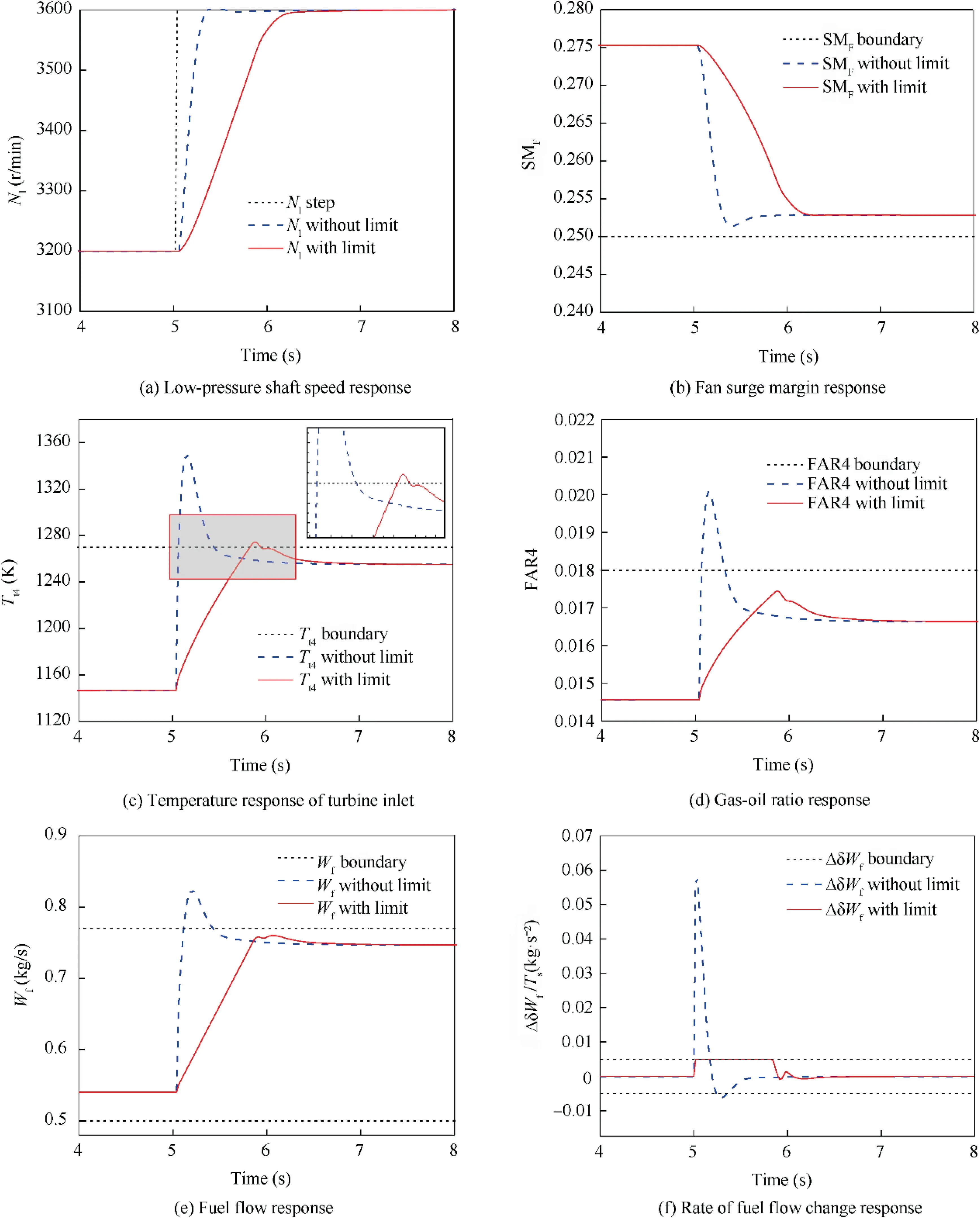
Fig. 12 Comparison of effect of model predictive controller before and after addition of restrictions when model is not accurate.
The above procedure illustrates the effectiveness of the designed model predictive controller in target tracking and limiting protection.
4.2. Impact of predictive model in controller
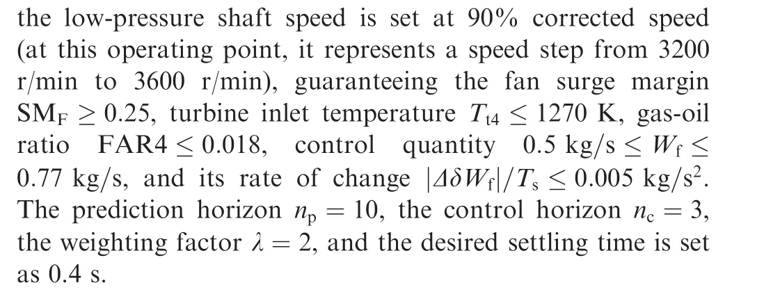
It is shown in Fig. 12 that when there is a big step in the low-pressure shaft speed, the controller can control the engine to track the input with no static error.However,the inaccurate predictive model, which is linearized at 80% corrected rotational speed, can no longer accurately reflect the properties of the nonlinear model in the transition process.This is mainly reflected in the fact that turbine inlet temperature cannot be well restricted. In this situation, the overshoot is around 4 K, which tends to increase compared with the overshoot of 2.5 K when the rotational speed is set at 85%corrected speed.
In conclusion, every model predictive controller can only accurately control the engine model in a small range because the predictive model is accurate in a small range. To control the engine model in a wide range,the sectional control method should be taken.This paper uses a scheduling scheme to combine several model predictive controllers to form a wide-range model predictive controller.
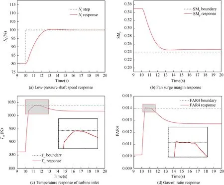
Fig. 13 Responses of a step at non-nominal point.
4.3. Simulation and analyses of wide-range model predictive controller
To fully verify the control effect of the wide-range model predictive controller, two simulations are conducted. One is to conduct a wide range of transition from 80% to 100% of the corrected rotational speed of the low-pressure shaft at a nonnominal point where the inlet altitude and Mach number are guaranteed to remain unchanged. Another is to vary the inlet altitude and Mach number while guaranteeing a 100%corrected rotational speed.We observe the response of the system in both cases.
4.3.1. Keeping inlet altitude and Mach number constant, and giving rotational speed a step
The selected working point is that the inlet Mach number is 0.23, and the altitude is 11000 m. Give a step from 80% to 100% of the corrected speed to the controller. Ensure that the limited output fan surge margin SM≥0∙24, the turbine inlet temperature T≤1040 K, and the gas-oil ratio FAR4 ≤0∙014. The system response is shown in Fig. 13.
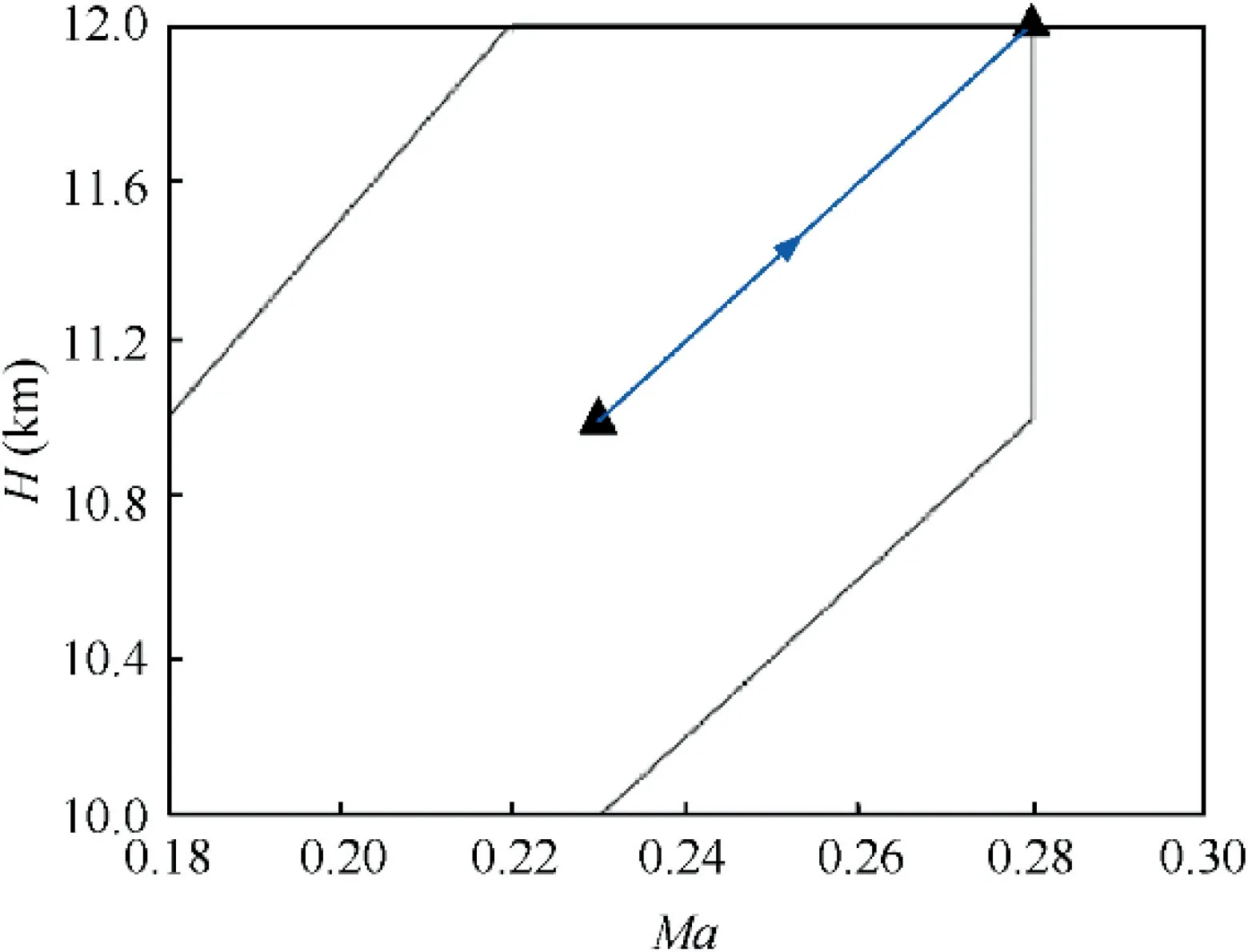
Fig. 14 Schematic diagram of variation of altitude and Mach number.
As can be observed in Fig.13,the system can achieve static error-free control,and the restricted quantity can work when a large step in rotational speed is taken at a non-nominal point.With the limiting quantity working, the adjusting time is approximately 3 s. During acceleration, the FAR4 limit acts first, and then the turbine inlet temperature Treaches the limit. As can be seen in Fig. 13(d), there is a very small overshoot in the restricted quantity. By analyzing this phenomenon, it can be assumed that it is caused by the inability of the model to match perfectly. Through the simulation above,the results show that the wide-range controller designed in this paper can realize the transient state control of the engine with a wide range of speed variation within the flight envelope.
4.3.2.Keeping rotational speed constant,and giving inlet altitude and Mach number a step
Starting at the flight point with Mach number 0.23 and an altitude of 11000 m, we keep the corrected speed at 100% and change the flight point to Mach number 0.28 and an altitude of 12000 m. Changes in the inlet parameters are shown in Fig. 14.
Before proceeding with the system simulation, it should be noted that the restriction needs to be relaxed in case of a wide range of changes in the import conditions. Otherwise, the model may fail to get a result, and the degree of relaxation of the restriction is determined by the change in the import conditions.After performing the steps,the response of the system is plotted in Fig. 15.
Analyzing Fig. 15, we know that the step in altitude and Mach number occurs at 15 s, at which point the system’s steady state is broken and the controller can bring the system back to the set rotational speed value after 2 s with no static error. This example illustrates the ability of the designed wide-range controller to achieve control of the engine as flight conditions change within the control area.
By summarizing the above two cases, it is shown that the wide-range model predictive controller designed in this paper can adjust the output based on the three control quantities of inlet height,inlet Mach number,and low-pressure shaft corrected speed according to the designed scheduling scheme,and then realize the engine transition state control in the flight envelope with good dynamic effect.
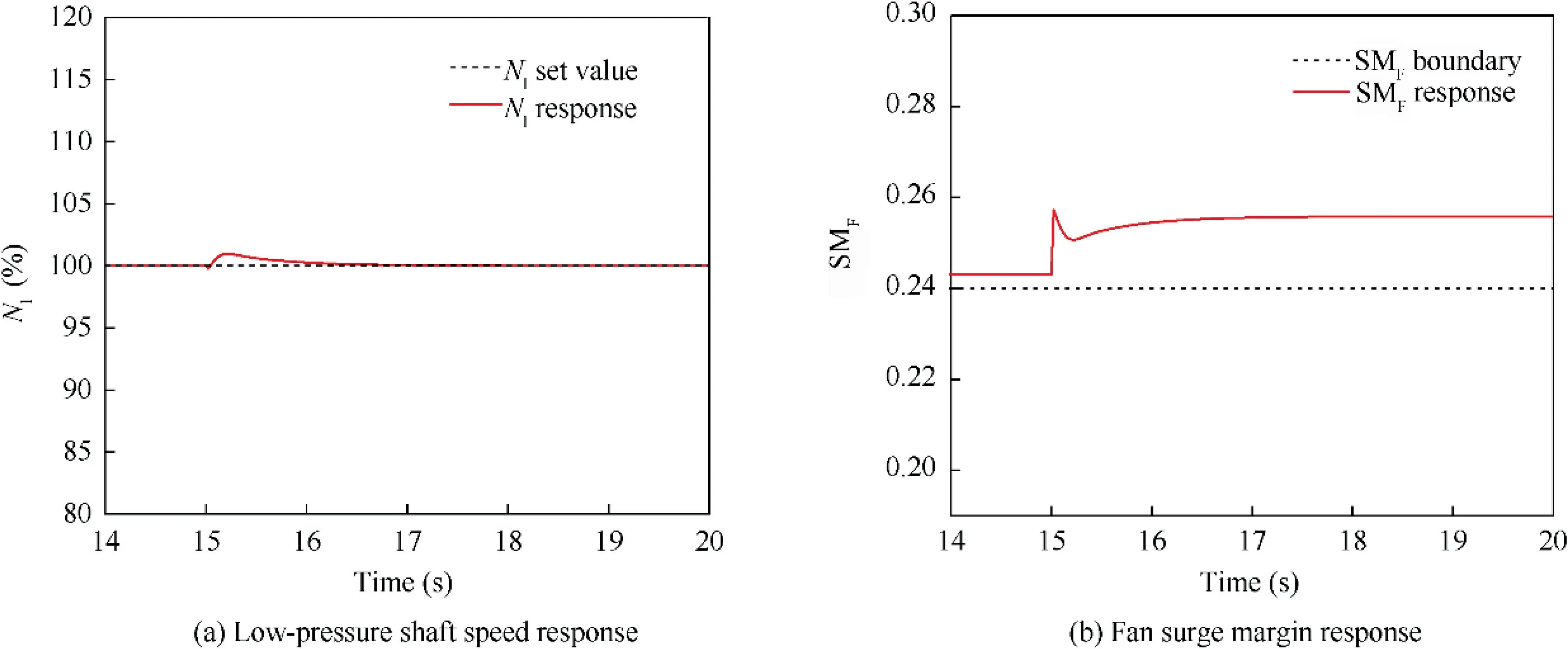
Fig. 15 Responses of a step in altitude and Mach number.
5. Conclusions
In this paper,a three-layer nested wide-range model predictive controller is designed to achieve control of the engine. The controller avoids the conservatism problem caused by conventional controllers due to the presence of min–max selector architectures and extends the study of controllers with nonmin–max selector architectures.
The designed univariate model predictive controller can control the engine well in a small range of rotational speed,but because the linear prediction model on which the controller is based cannot maintain relatively high accuracy in a wide range of parameter changes, some limits may be exceeded. Therefore, this paper finally chooses to use a segmented controller and scheduling plan to form a wide-range model predictive controller, and through the closed-loop verification of the controller,it is verified that its effectiveness and dynamic performance meet the design requirements of the engine control system.
The authors declare that they have no known competing financial interests or personal relationships that could have appeared to influence the work reported in this paper.
This study was supported by the National Science and Technology Major Project of China (No. J2019-I-0020-0019).
 Chinese Journal of Aeronautics2022年7期
- Chinese Journal of Aeronautics的其它文章
- An online data driven actor-critic-disturbance guidance law for missile-target interception with input constraints
- Study on excitation force characteristics in a coupled shaker-structure system considering structure modes coupling
- Smooth free-cycle dynamic soaring in unspecified shear wind via quadratic programming
- Active and passive compliant force control of ultrasonic surface rolling process on a curved surface
- High dynamic output feedback robust control of hydraulic flight motion simulator using a novel cascaded extended state observer
- Composite impact vector control based on Apollo descent guidance
