A unified formulation of optimal guidance-tocollision law for accelerating and decelerating targets
Young-Won KIM, Boseok KIM, Chng-Hun LEE,*, Shoming HE
a Department of Aerospace Engineering, Korea Advanced Institute of Science and Technology, Daejeon 34141, Republic of Korea
b School of Aerospace Engineering, Beijing Institute of Technology, Beijing 100081, China
KEYWORDS Guidance-to-collision law;Optimal guidance;Optimal error dynamics;Target acceleration or deceleration;Unified formulation
Abstract This paper provides a unified formulation of optimal guidance-to-collision law for a target with an arbitrary acceleration or deceleration. The collision course for general target acceleration or deceleration is first determined from the engagement geometry in conjunction with the nonlinear engagement kinematics in the proposed approach. The heading error defined in the collision course is then adopted as a variable to be nullified for accomplishing the intercept condition.The proposed guidance law is derived based on the heading error dynamics and the optimal error dynamics to ensure optimality and finite-time convergence. As illustrative examples, the proposed guidance command for a constant target acceleration and a target deceleration in the form of a quadratic function of speed are provided. Additionally, the time-to-go prediction method is suggested for implementing the proposed method. The characteristics of the proposed guidance command are analytically investigated to provide insight into the proposed method.The key benefits of the proposed method lie in not producing unnecessary guidance commands near a target compared to other methods and ensuring optimality in guidance command even in the nonlinear engagement kinematics. Finally, numerical simulations are performed to validate the proposed method and to show our findings.
1. Introduction
The classical Proportional Navigation Guidance (PNG)has a long history of success, and it has been extensively applied to numerous guided systems over the past several years. Even in recent years, the classical PNG has been still receiving great attention from many researchers, and there have been active and continuous efforts in advancing it. It is recognized that the key enablers for leading the great success of the classical PNG are its simplicity and efficiency in implementation.The classical PNG is based on a simple underlying principle that if the Line-of-Sight (LOS) angle between an interceptor and a target does not change in the collision triangle, the interceptor ends up intercepting the target. Therefore,it is working in a way to nullify the LOS rate in a finite-time.To accomplishing this condition, the PNG command is given in the form of the LOS rate feedback with the closing speed and the navigation constant. Additionally, it has different characteristics depending on the navigation constant. The PNG with N=3 has been known as the optimal solution for minimizing the control energy under a specific engagement condition.
Despite these favorable properties,there are some points to be improved in the classical PNG. One of them is that the underlying principle of the classical PNG is only valid for a specific interceptor and target motion.In other words,zeroing the LOS rate is equivalent to the intercept condition only when the interceptor and the target are moving at constant speeds.Due to this inherent property of the classical PNG, it is expected that the guidance performance can be degraded under the engagement scenarios where the underlying assumption or premise does not hold.As remedies to this issue,recently,there have been some research activities.
The first approach to handle the above issue is to modify the classical PNG. The main idea of this approach is to determine an accurate LOS rate reflecting missile or target motions,and guidance command is then determined by utilizing the concept of the LOS rate feedback. Based on this concept, a modified PNG was proposed for a variable-speed missile caused by a constant missile axial acceleration in reference Ref. [6]. The author in Ref. [7] devised a homing guidance law for an accelerating target with a constant thrust. In Ref.[8], new homing guidance for collision course was proposed under a case where the missile and target axial acceleration or deceleration are constant. In Ref. [9], the authors devised a new guidance law for a missile with varying speed due to a constant thrust or an aerodynamic drag. The authors in Ref.[10] suggested a new guidance law with the impact angle constraint for various missile and target motions. This study considered a constant missile axial acceleration, a constant target axial acceleration,and a constant target lateral acceleration.In Ref. [11], a new biased PNG for decelerating targets due to aerodynamic drag was proposed. In Ref. [12], a new homing guidance law was developed for a high-speed target, considering a constant missile axial acceleration, a constant target lateral acceleration,and a varying target axial acceleration caused by aerodynamic drag.
Although there have been various research activities based on the previous studies, there are still some points to be improved. To be more specific, the optimality was not addressed,and rigorous analysis on the finite-time convergence was limited in the previous studies.Accordingly,guidance laws for various missile or target motions based on the optimal controlapproaches have also been reported in recent years. In Refs. [13,14], an optimal homing guidance law for an accelerating interceptor in the exo-atmospheric region was studied.In Ref. [15], a weighted optimal guidance law for varying missile speeds with a predicted missile speed profile was developed.In Ref. [16], an optimal impact angle guidance based on the collision geometry approach was proposed for various missile and target motions with various combinations of constant missile and target axial or lateral accelerations.Compared to the modified PNG approach, few studies considering interceptor or target motions based on the optimal control approach are available in the open literature. Furthermore, the previous guidance laws based on the optimal control approach mainly focuses on a specific missile motion or a constant target acceleration. Thus, the generalization for various target acceleration or deceleration is limited. Last but not least, the linearization of the nonlinear engagement kinematics is required in their formulations.
Motivated by the above observations, this paper aims to suggest the unified formulations of optimal guidance for arbitrary target accelerations or decelerations. The proposed approach is substantially different from the previous works,and it does not require any linearization as the collision geometry and the nonlinear engagement kinematics are directly used. To be more specific, in the proposed approach,the collision course reflecting general target accelerations or decelerations is first determined. An accurate heading error is then defined on the collision course, and the corresponding heading error dynamics is derived. The proposed guidance command is realized in a way to optimally nullify the initial heading error in a finite-time by using the optimal desired error dynamics. As illustrative examples of showing the generalization of the proposed method, we provide the proposed guidance command for a constant target axial acceleration and a target deceleration caused by aerodynamic drag.For implementing the proposed method, the time-to-go calculation method is also proposed. Additionally, the proposed guidance command characteristics are investigated to offer better insight into the proposed method. The optimality of the proposed guidance command and the finite-time convergence of the heading error under the proposed method are analyzed. The proposed guidance command in a nearcollision course is also examined. The key features of the proposed method lie in the generalization for target accelerations or declarations, the optimality of the guidance command, and the exact nonlinear nature of its formulation. Hence, the proposed method does not produce unnecessary guidance commands near a target compared to existing methods. This property is beneficial for ensuring some operational maneuvering margin to cope with unexpected situations during the engagement. Additionally, the proposed method can save the control energy usage. Numerical simulations are performed to show the feasibility of the proposed method and to verify our findings.
The rest of this paper is structured as follows.In Section 2,the formulation of the guidance problem to be solved is addressed. Section 3 describes the derivation of the proposed method in detail.In Section 4,some investigations on the proposed guidance are offered. Numerical simulation results are provided in Section 5. Finally, the conclusions of this paper are offered in Section 6.
2. Problem formulation
In this section,the engagement kinematics used in this work is first formulated,and the guidance problem to be solved is then explained.
2.1. Engagement kinematics
This study mainly considers the interception engagement between an interceptor and a target with an arbitrary acceleration or deceleration. To formulate the engagement kinematics, we consider some general assumptions and premises as follows.
Assumption 1. The planar engagement kinematics is considered.
Assumption 2. The interceptor and the target are treated as the point masses with ideal dynamics.
Assumption 3. The interceptor speed is assumed to be constant during the engagement.
Assumption 4. The gravity is omitted in the guidance problem formulation.
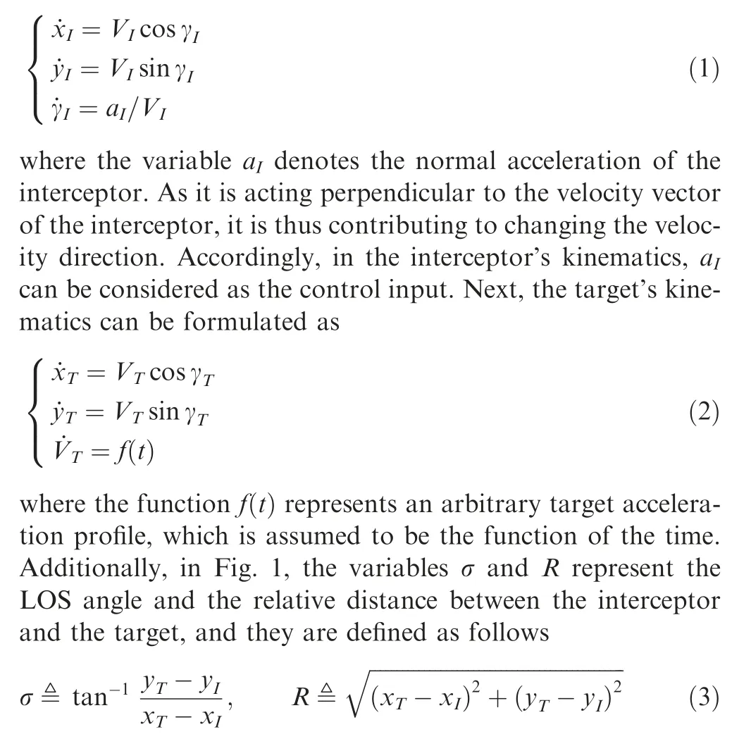
It is worth pointing out that the above assumptions and premises have been widely adopted in the guidance problem so far. (Assumption 1) The interceptor motion in a threedimensional space can be decoupled into two identical motions in the perpendicular plane if the interceptor’s roll motion is rapidly stabilized. Therefore, the engagement kinematics in a two-dimensional can be considered for deriving a guidance law based on the well-known separation concept.(Assumption 2)In most interceptors using the separated guidance and control structure, the guidance and control loops’bandwidths are sufficiently separated. Accordingly, the guidance problem can be treated as the kinematics problems, and the interceptor dynamics can be ignored when designing guidance laws.(Assumption 3)As the interceptor speed is usually slowly varying compared to other state variables during the engagement, it can be regarded as a piece-wise constant at each time step. (Assumption 4) As the relative engagement kinematics between the interceptor and the target is considered for guidance law designs,the gravity acting on both the target and the interceptor can be omitted in the relative engagement kinematics. According to the above assumptions and premises, we consider the planar engagement geometry between the interceptor and the target, as described in Fig. 1. Here, the coordinate system denoted by (X-O-Y)is the inertial reference frame to describe the interceptor position and the target position.Points I and T represent the interceptor and the target, and their variables are expressed by the subscripts I and T, respectively. For instance, the variables Vand γare the speed and the flight path angle for the interceptor. Likewise, the variables for the target can be defined.
Based on the assumptions, the interceptor’s kinematics can be written as
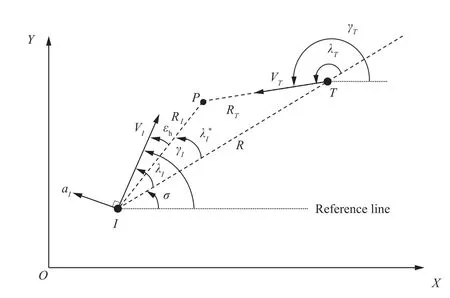
Fig. 1 Engagement geometry and definitions of variables.
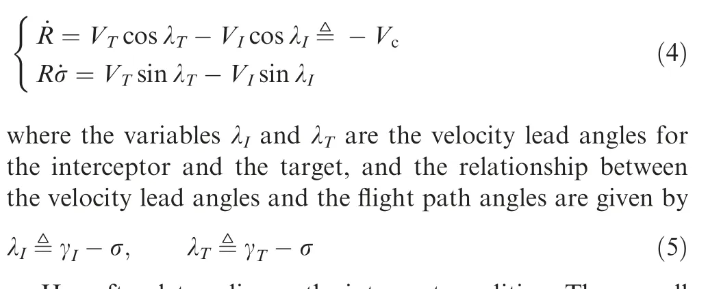
Based on the definitions of σ and R,the relative engagement kinematics between the interceptor and the target in the polar coordinate system(along and perpendicular to the LOS direction) is given by
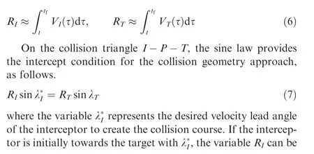
Hereafter,let us discuss the intercept condition.The overall goal of the guidance is to drive an interceptor to hit a target in a finite-time. From the collision geometry standpoint, the intercept condition can be equivalently thought of as the condition to achieve a collision course before reaching a target.In Fig. 1, the triangle connecting three points I-P-T depicts the collision course,where point P denotes the intercept point.The line segment between I and P is expressed by R, and it is the distance traveled by the interceptor during the engagement(or the remaining interceptor’s distance of the interception).Similarly, the line segment between T and P is denoted by R,and it represents the distance traveled by the target during the engagement(or the remaining target’s distance of the interception).By definition,the variables Rand Rcan be approximately expressed as
2.2. Problem statement
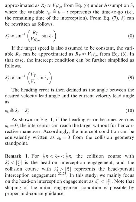
The main issue to be tackled in our study is discussed in this subsection. The well-known classical Proportional Navigation Guidance(PNG)lawhas been devised based on the underlying principle that retaining geometry condition ˙σ=0 leads to the interception. However, from Eq. (4), it can be readily observed that the condition ˙σ=0 is identical to Eq. (9). It means that the intercept condition ˙σ=0 is only valid for the interceptor and the target with constant speeds. Thus, for an engagement case where the variation of the target speed is not negligible, retaining the condition ˙σ=0 does not lead to the exact intercept condition as given in Eq. (8).
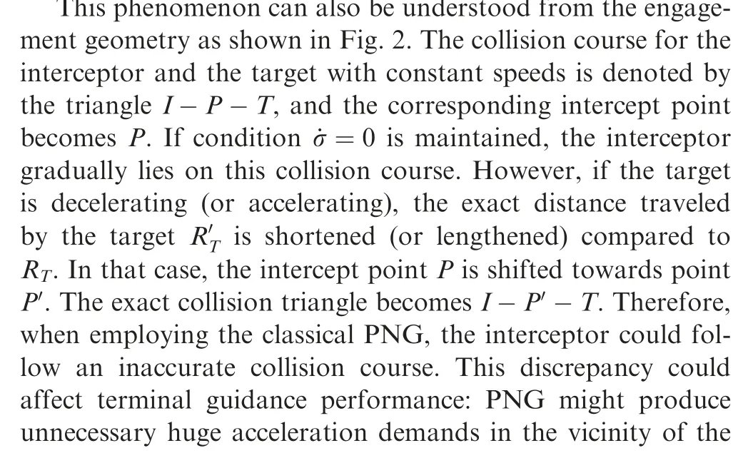
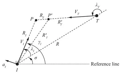
Fig. 2 Collision course change due to target deceleration.

3. Proposed guidance law
This section describes the unified formations of guidance law for decelerating or acceleration targets. The proposed approach is based on the fact that the guidance problem for intercepting the target could be considered as the control problem for nullifying the heading error from the collision geometry standpoint. In this context, an accurate heading error reflecting the exact target motions as much as possible is determined from the collision geometry and the nonlinear engagement kinematics as shown in Eq. (4). The guidance problem is then formulated as the heading error dynamics in the unified form. The finite-time tracking problem with respect to the heading error is then solved in conjunction with the optimal error dynamics.
3.1. Heading error dynamics
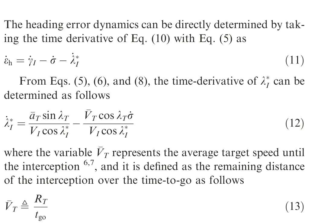
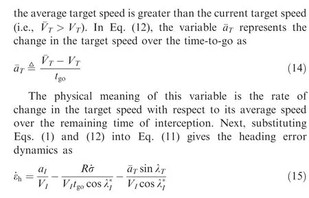
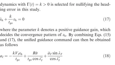
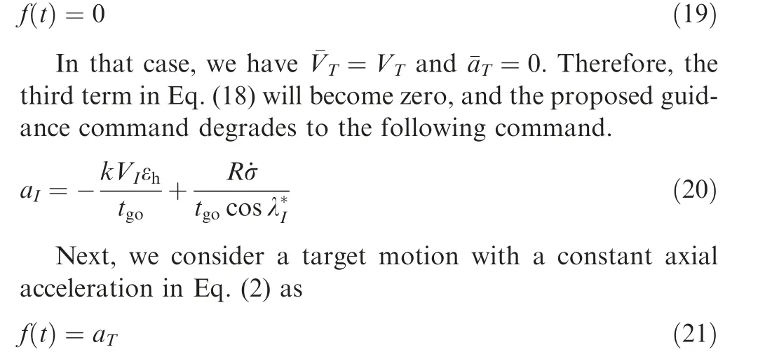
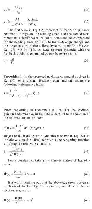
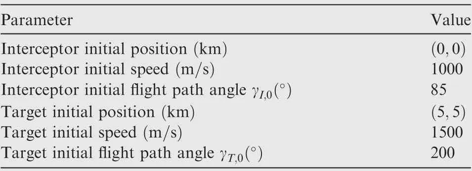
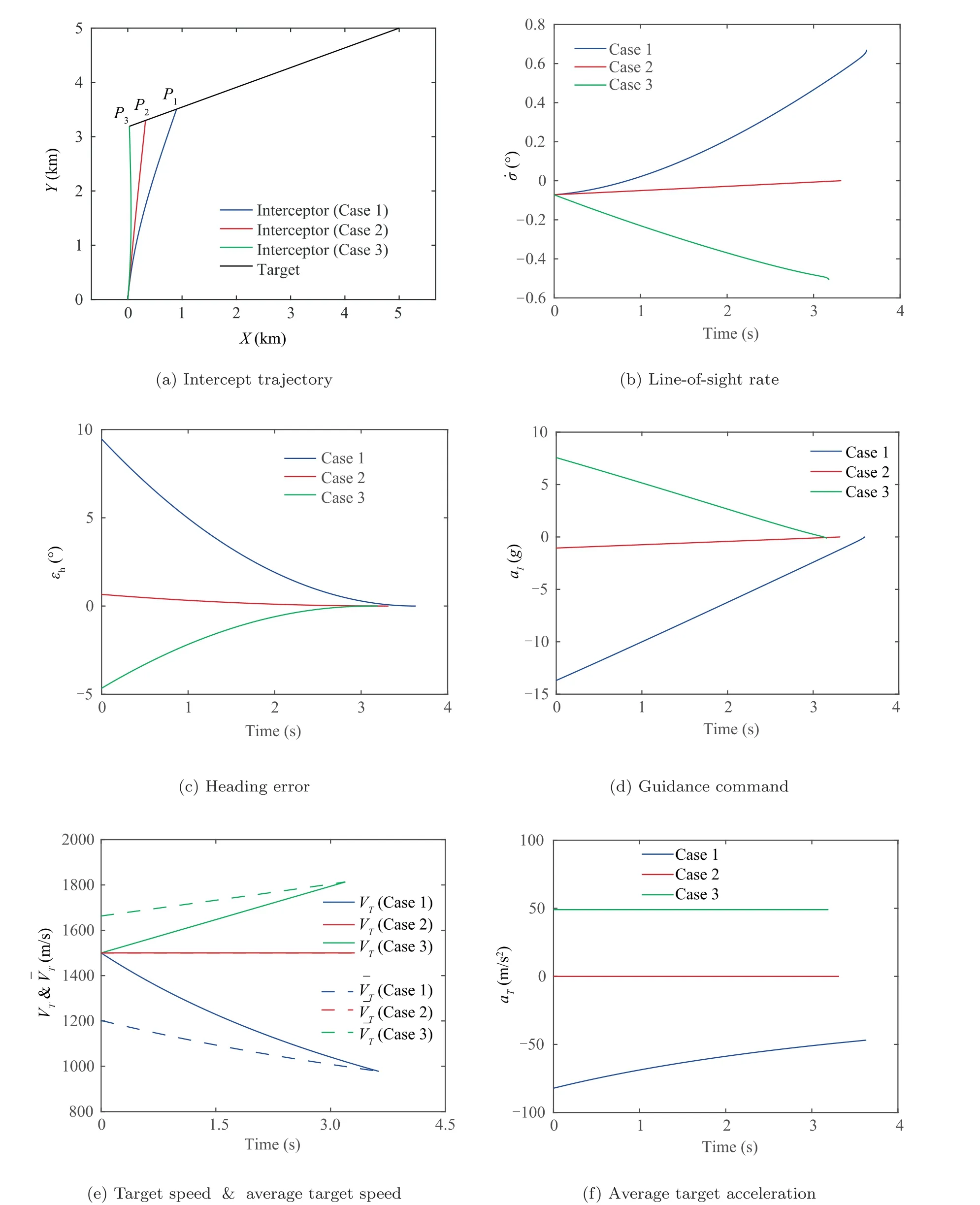
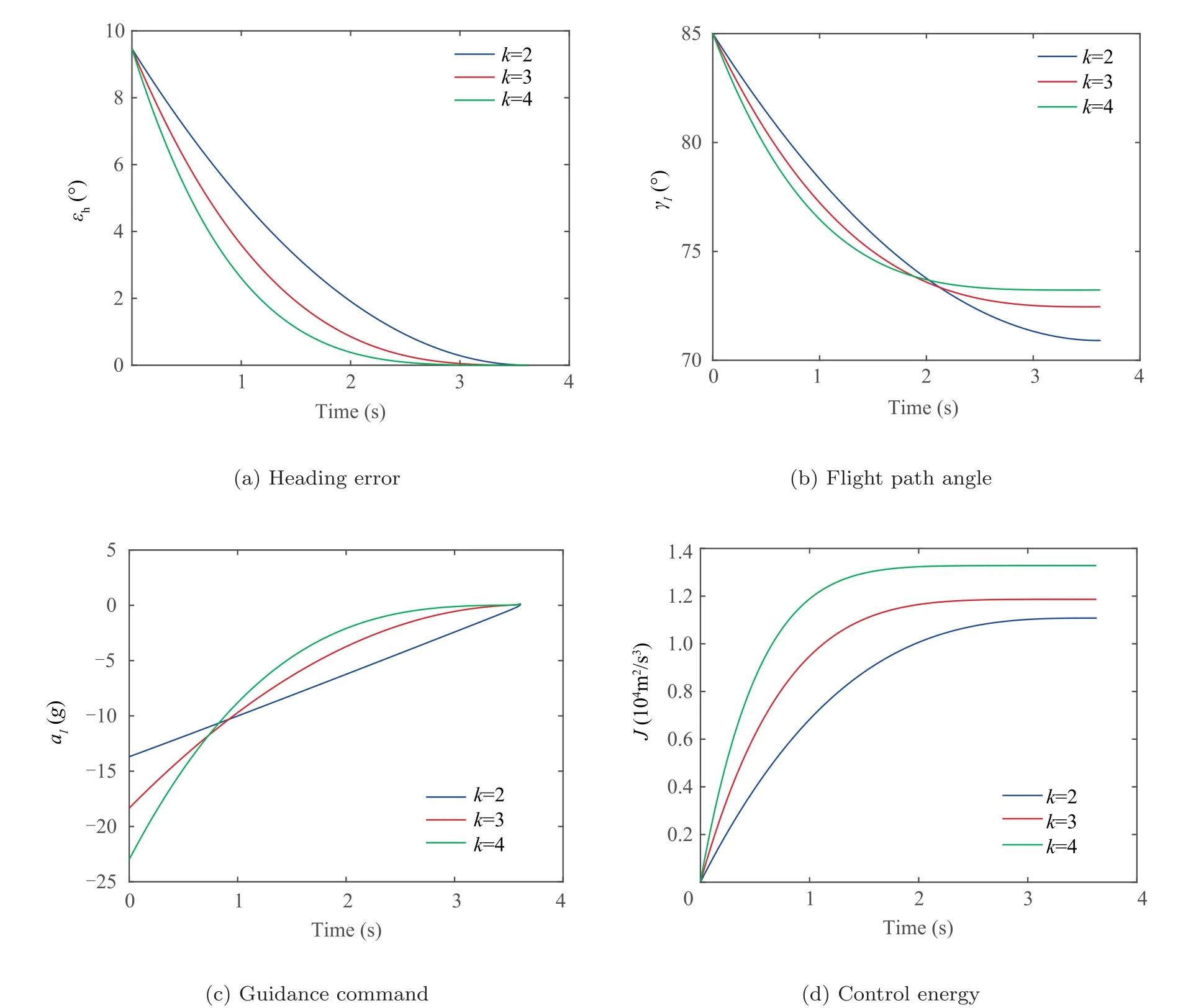
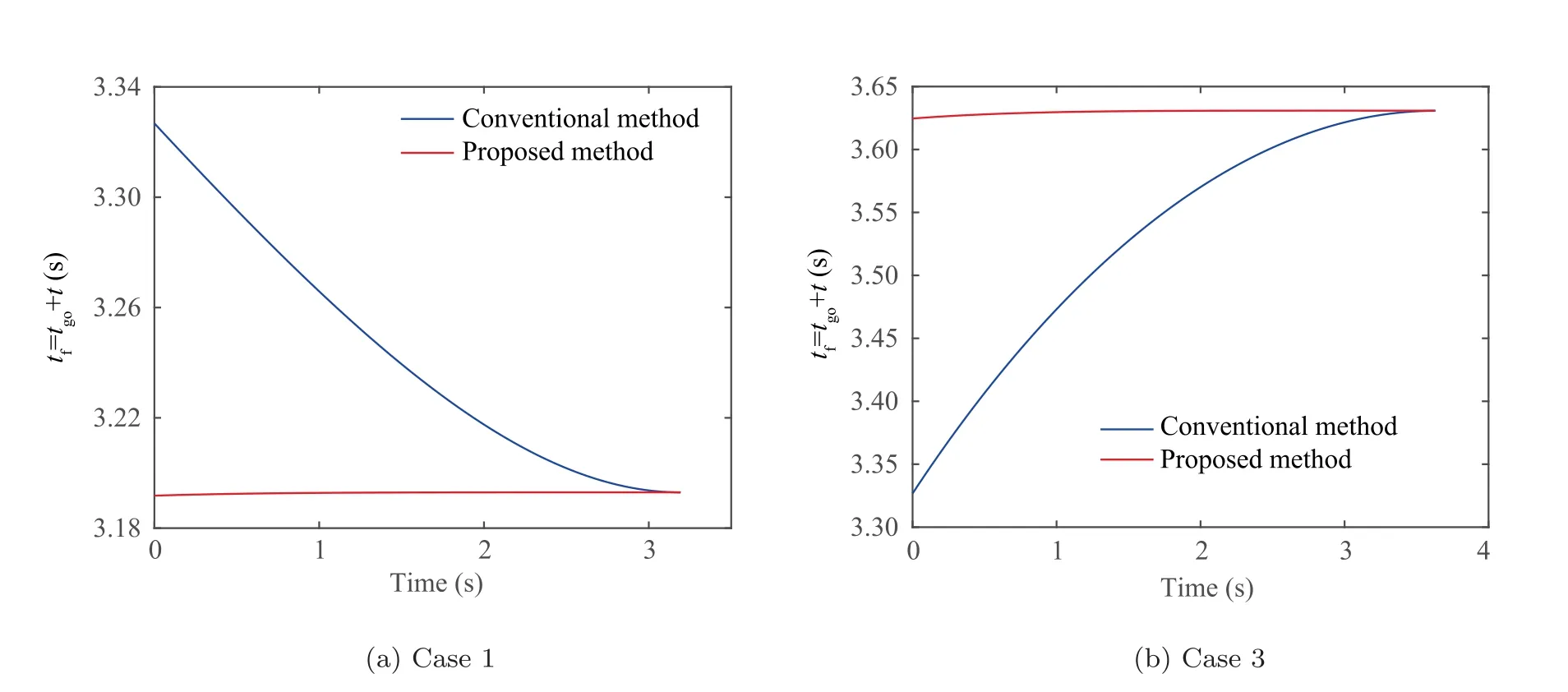
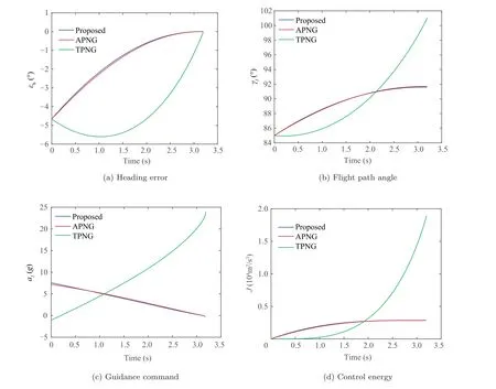
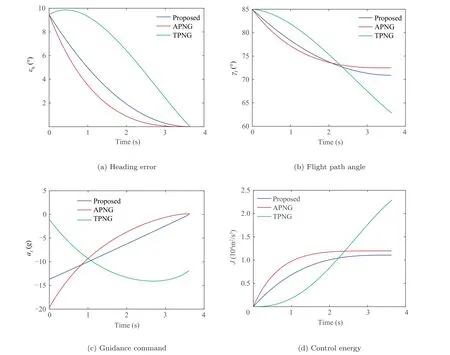
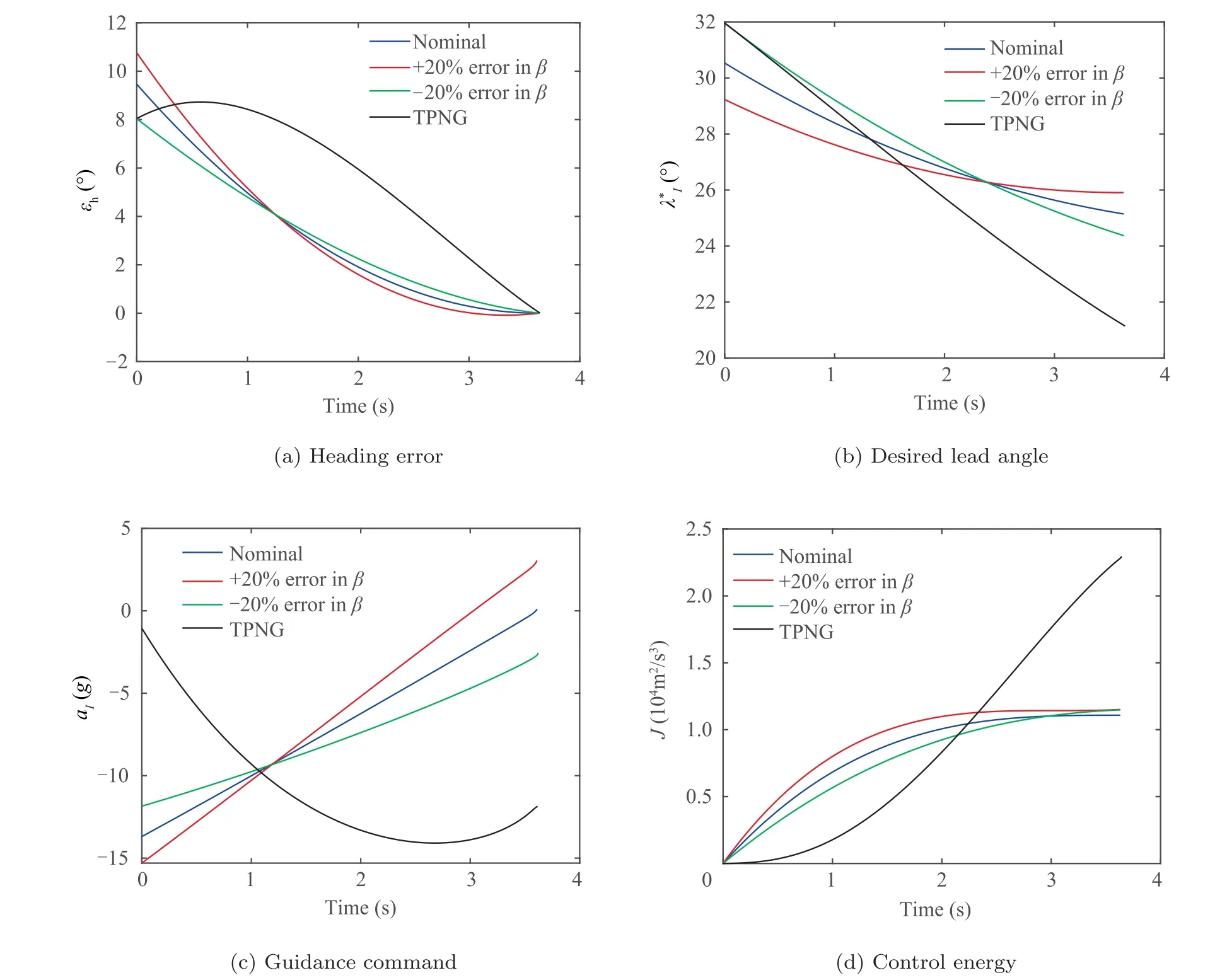
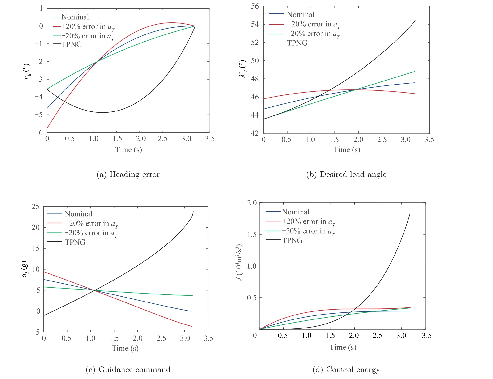
The graphical interpretation of ˉVis shown in Fig.3.If the target speed is constant, the average target speed becomes the current target speed as ˉV=V. If the target is decelerating,the average target speed is smaller than the current target speed (i.e., ˉV Fig. 3 Graphical interpretation of ˉVT. From Eq. (15), it is worth noting that the heading error dynamics consists of three distinct terms.The first term means the change of εdue to altering γby a.The second term represents a drift term for ˙εdue to the LOS angle change caused by the shift in the positions of the interceptor and the target.Finally, the physical meaning of the last term is an additional change of εdue to the target deceleration or acceleration. In the heading error dynamics, the normal acceleration acan be regarded as the control input for regulating the heading error.Remark 2. Note that when the target is moving along the LOS direction, i.e., sin λ=0, target acceleration or deceleration does not introduce an additional ˙ε, as shown in Eq. (15). Hereafter, the unified guidance command for acceleration or decelerating targets is determined in a way to solve the finitetime tracking problem for the heading error by utilizing the heading error dynamics. According to our previous study,the optimal error dynamics for any tracking error (i.e., e) is given by where Γ(t ) is any positive function to be designed for various guidance operational goals. For simplicity, the desired error The proposed guidance command consists of three distinct terms.The physical meanings of the three guidance commands and the properties of the proposed guidance command will be further discussed in the following section. Remark 3. In Eq. (18), the first term can be considered as the feedback guidance command for nullifying the heading error.The remaining terms are the feedforward guidance commands compensating for the nonlinear terms in the heading error dynamics in Eq. (15). If the guidance gain k is chosen as a sufficiently large value, the magnitude of the first term is typically more dominant than the magnitudes of other terms.Besides, as it will be shown in the next section, the second guidance command can be further decomposed into a guidance command for nullifying the heading error and a guidance command to compensate for the target motion.Therefore, although the proposed guidance command is composed of three distinct terms, the composite error is not encountered due to the form of the summation of the three terms. Remark 4. It is worth pointing out that although the proposed approach is devised for an accelerating or decelerating target,the proposed method can also be applied to various interceptor or target motions, such as a lateral target acceleration or axial interceptor acceleration. In this subsection, as illustrative examples,the proposed guidance commands for specific target motions are provided.First,a target with a constant speed is considered.In Eq.(2),the target motion is given by where the variable ais the axial acceleration of the target.For the constant axial acceleration, the target speed Vcan be obtained by integrating Eq. (21) as Remark 5. If the target acceleration or deceleration can be modeled as an integrable function f(t ), the proposed method can be applied to any target acceleration or deceleration that is not provided in this subsection. Remark 6. In practical application,a target model f(t )with its parameters is required for implementing the proposed method.These parameters can be accurately estimated by a dedicated estimator by utilizing measurements from a radar seeker and an inertial navigation system. In this section, the characteristics of the proposed guidance law are investigated to provide better insight into the proposed method. Table 1 Target motions used in the simulation studies. First, the optimality of the proposed guidance command is addressed based on the well-known optimal control theory.From Eq. (18), the proposed guidance command can be decomposed into the two components as follows where W(t) represents the initial value of the weighting function. Since a constant weight on the performance index does not affect the optimal solution, combining Eq. (43) with a time-varying term and Eq. (40) yields Eq. (39), which completes the proof. The result of Proposition 1 is useful to understand the pattern of the feedback guidance command according to changes in the guidance gain k. As shown in Eq. (39), the feedback guidance command will be more penalizing as t →tunder k>1 because the weighting value increases as t →t. We can readily expect that the resultant guidance command will decreases as t →tunder k>1. Based on this analysis, the guidance gain needs to be chosen as k>1 for ensuring the finite guidance command.The condition k>1 is also desirable for ensuring the decreasing pattern of the guidance command for saving guidance command authority to cope with an unexpected situation in the vicinity of the target. Next, the finite-time convergence of the heading error under the proposed guidance command is investigated.This property is critical to achieving the intercept condition. The answer to this equation is summarized in Proposition 2. Additionally,the result of Proposition 2 can give a general insight into the convergence pattern of the heading error. As shown in Eq.(44), the heading error will more rapidly converge to zero as the guidance gain k increases. In the proposed method, the selection of the guidance gain k decides the overall convergence pattern of the heading error. Proposition 2. For k>0,the heading error will be nullified as t →tunder the proposed guidance command. Proof. By substituting Eq. (36) into Eq. (38), we can obtain the closed-loop dynamics of the heading error as shown in Eq. (17). Since it is given in the form of the Cauchy-Euler equation, the closed-form solution of the heading error can be readily determined as where εdenotes the initial heading error.From Eq. (44),we can readily predict that the heading error becomes zero as t →tunder k>0, which completes the proof. Table 2 Baseline initial engagement conditions. Fig. 4 Simulation results of the proposed guidance law with various target motions. Fig. 5 Simulation results of the proposed guidance law with various guidance gains under Case1. Fig. 6 Simulation results of the proposed time-to-go prediction method. Fig. 7 Comparison with other guidance laws under Case3. In this subsection, we analyze the behavior of the proposed guidance law in a Near-Collision Course (NCC). According to Proposition 3,the proposed guidance command will behave the True Proportional Navigation (TPN) with the two augmented terms in NCC. As shown in Eq. (45), the first command term represents the TPN guidance command. If k=2 is used, the effective navigation constant of the TPN guidance command becomes N′=3.In Eq.(45),the target deceleration or acceleration perpendicular to the LOS direction (i.e., the term ˉasin λ) can be viewed as the target maneuver. Thus,the second term can be considered as the augmented guidance command to compensate for the target maneuver caused by the target deceleration or acceleration. Finally, the third term can be regarded as the guidance command to cope with the collision course change due to the target deceleration or acceleration along the LOS direction. Fig. 8 Comparison with other guidance laws under Case1. In NCC, the heading error εis small enough to approximate Eq. (46) as By substituting Eqs. (48) and (50) into Eq. (18), we have Eq.(45), which completes the proof. In this section, numerical simulations are conducted to validate the performance of the proposed method and to verify the analytical findings obtained in Section 4. The first simulation is conduced to investigate the basic characteristics of the proposed guidance command with various target motions. Here, we consider the three target motions: a constant speed target, a constant target acceleration, and a time-varying target deceleration, and their parameters are summarized in Table 1. In the second simulation, the proposed guidance law with various design parameters is tested.Next, the proposed time-to-go calculation method is compared with the conventional method in the third simulation.Additionally, the proposed guidance law is compared with the existing methods. Finally, the guidance performance of the proposed method in the presence of the target estimation error is investigated. The baseline initial engagement conditions for the simulation study are provided in Table 2. Additionally, the baseline guidance gain of the proposed guidance command is chosen as k=2, which is equivalent to the navigation constant of PNG N=3 in NCC. Fig. 9 The guidance performance in the presence of target estimation error under Case1. In this subsection, the proposed guidance law is tested against various target motions, as shown in Table 1. Fig. 4 shows the simulation results of the proposed method for various target motions. In the intercept trajectory as shown in Fig. 4 (a),we can observe that the proposed guidance law can successfully intercept the target in each case,where P,P,and Prepresent the intercept points for each case. The intercept points are shifted as the target speeds vary. The LOS rate converges to a non-zero value in Case1 and Case3, and the final LOS rate becomes zero in Case2 only,as shown in Fig.4(b).These results obtained confirm our premise as discussed in Section 2.2. Fig. 4 (c) shows that the heading error converges to zero in a finite-time under the proposed method in all the cases.Accordingly, the guidance command linearly decreases as t →t, and it ends up converging to zero, as shown in Fig. 4(d). This property is always recommended in guidance operations to ensure guidance command authority to cope with an unexpected situation during an engagement, as discussed in Refs. [25,26]. Fig. 4 (e) represents the time profile of the current target speed and the average target speed. It indicates ˉV In this subsection,the characteristics of the proposed guidance law are investigated according to change in the guidance gains.As a test scenario, Case1 is considered in this simulation. The guidance gains are selected as k=2,k=3, and k=4, respectively. As shown in Fig. 5 (a), as the guidance gain increases,the heading error rapidly converges to zero. Additionally,the flight path angle also rapidly converges to a certain value,as shown in Fig.5(b).These results imply that the interceptor can be quickly laid on the collision course as the guidance gain increases. However, we can observe that more acceleration demand and control energy are required as the guidance gain increases, as shown in Figs. 5 (c) and 5 (d). Although not included here, the characteristics of the proposed guidance law according to change in the guidance gains have similar tendencies even in Case2 and Case3. In this subsection, the proposed time-to-go prediction method is compared with the conventional time-to-go prediction method under various target motions, as shown in Table 1.In Case2 (i.e, constant target speed), as the proposed method degrades to the conventional method, Case2 is omitted in the test scenario. Figs. 6 (a) and 6 (b) provide the comparison results for the two prediction methods under the test scenarios Case1 and Case3, respectively. We observe that the conventional method tends to under-estimate the time-to-go in Case1 and over-estimate the time-to-go in Case3.Additionally,in the conventional method, the prediction accuracy is poor at the beginning. Conversely, the results obtained indicate that the proposed method tends to under-estimate the time-to-go in Case1 and Case3. However, the proposed method ensures a quite accurate prediction of the time-to-go,as shown in Figs.6(a) and 6 (b). Fig. 10 The guidance performance in the presence of target estimation error under Case3. In this subsection, the proposed guidance law is compared with existing methods to validate the superiority of the proposed method. In the simulation study, TPN Guidance(TPNG)and APN-type Guidance (APNG) as studied in Ref. [7] are chosen as comparative group. The acceleration command for TPNG is given by Since the relationship between the guidance gain of the proposed guidance command and the navigation constant of PNG command is given by N=k+1,N=3 is used for a fair comparison in this simulation. Fig. 7 shows the comparison results of the three guidance laws under Case3.For a constant target acceleration,the proposed guidance law behaves like APNG in NCC. Thus, the proposed method and APNG show similar guidance performance. Under these guidance laws, the heading error can be rapidly nullified and the guidance command converges to zero in a finite-time. On the other hand, in TPNG, we can observe that the heading error increases initially, and then it starts to decrease. This is because an inaccurate prediction of the collision course in TPNG. Accordingly, the guidance command increases as t →t, and more control energy is demanded.These properties are not desirable for guidance operation. Fig.8 provides the comparison results of the three guidance laws under Case1.The results obtained indicate that the guidance performance of APNG is degraded in that case. This is because that APNG is inherently developed under the assumption of a constant target acceleration, and this assumption does not hold in Case1. On the other hand, the guidance performance of the proposed guidance law is not degraded even in Case1 because the proposed guidance law is developed based on an accurate collision course reflecting an arbitrary target deceleration or acceleration. Additionally, the optimality of the feedback guidance command is also guaranteed in the proposed method. Compared to the existing methods, the proposed guidance law can effectively nullify the heading error,as shown in Fig. 8 (a), and the proposed guidance law demands less control energy, as shown in Fig. 8 (d). In this subsection, the guidance performance of the proposed method in the presence of the target estimation error. In this simulation, it is assumed that there are ±20% estimation errors in the target model parameters, as given in Eqs. (21)and (26). Figs. 9 and 10 show the simulation results with the target estimation error under Case1 and Case3, respectively. As shown in Figs. 9 and 10, the guidance performance slightly deteriorates compared to the nominal case (i.e., ideal case) if the estimation errors are encountered. It is worth pointing out that it is the common characteristic for most predictive guidance laws. In the proposed guidance case,the guidance commands at the final time become non-zero values due to the estimation errors, and slightly more control energy is used. However, it can be readily observed that the heading error always converges to zero even in the presence of the target estimation errors. Moreover, the guidance performance of the proposed method is still better than that of TPNG. This fact implies that even utilizing the target acceleration with estimation errors can improve the guidance performance over not utilizing it. This paper proposes a new optimal guidance-to-collision law for an arbitrary accelerating or decelerating target in a unified form. An exact collision course reflecting the target motion and the corresponding heading error is determined. The proposed guidance command is determined by nullifying the heading error in a finite-time and optimal way. The optimality of the feedback guidance command was shown, and the finitetime convergence of the heading error was proven. The proposed guidance law analysis in a near collision-course showed that the proposed guidance law could be considered as the proportional navigation guidance with the two augmented terms relating to the target acceleration or deceleration.The key benefit of the proposed method lies in the fact that it can be applied to various target accelerations or decelerations. As illustrative examples, the proposed guidance commands for the three specific target motions were provided. Finally,numerical simulations are conducted to verify the proposed approach. The simulation results confirmed the feasibility of the proposed time-to-go prediction method.Although the proposed approach is devised for an accelerating or decelerating target, the proposed method can also be applied to various interceptor or target motions. The authors declare that they have no known competing financial interests or personal relationships that could have appeared to influence the work reported in this paper.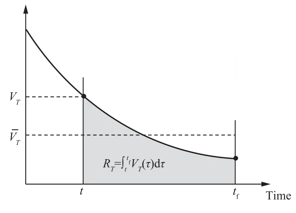
3.2. Unified guidance command

3.3. Illustrative examples of proposed method
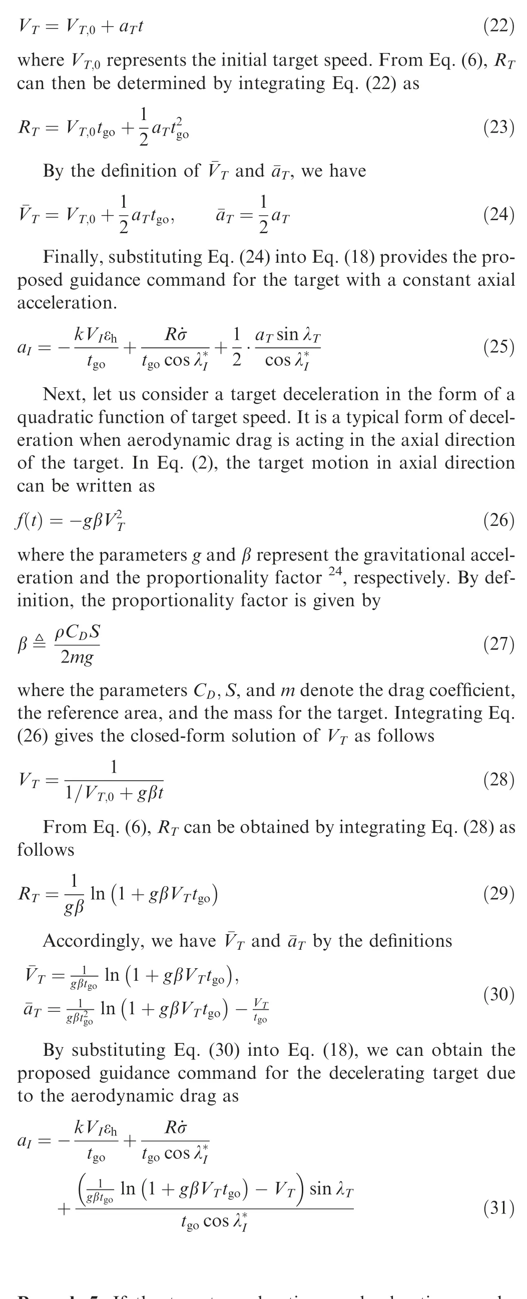
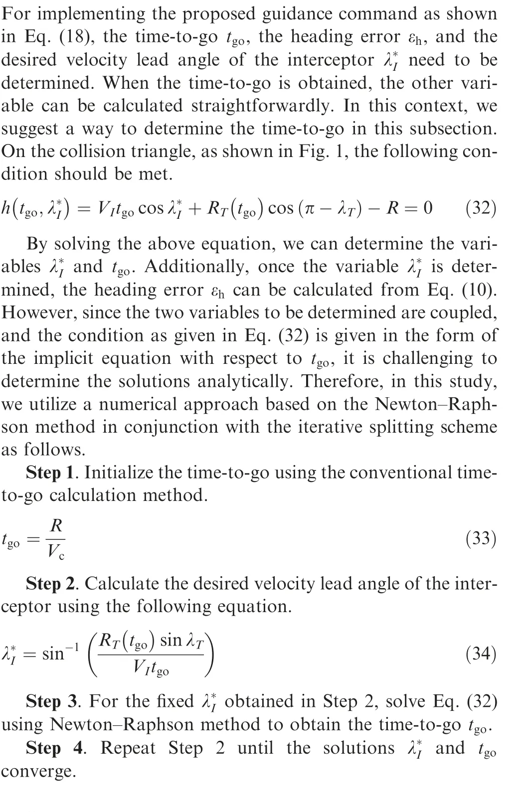
3.4. Proposed time-to-go prediction method
4. Characteristics of proposed guidance law
4.1. Optimality of proposed guidance command


4.2. Finite-time convergence of heading error

4.3. Proposed guidance command in near-collision course
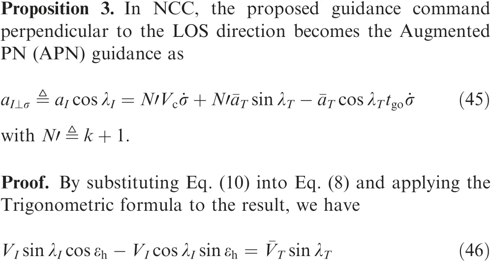
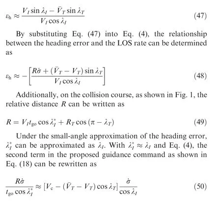
5. Numerical simulations
5.1. Performance with various target motions
5.2. Performance with various guidance gains
5.3. Performance of time-to-go prediction method
5.4. Comparison with other guidance laws


5.5. Robustness in presence of target estimation error
6. Conclusions
 Chinese Journal of Aeronautics2022年7期
- Chinese Journal of Aeronautics的其它文章
- An online data driven actor-critic-disturbance guidance law for missile-target interception with input constraints
- Study on excitation force characteristics in a coupled shaker-structure system considering structure modes coupling
- Smooth free-cycle dynamic soaring in unspecified shear wind via quadratic programming
- Active and passive compliant force control of ultrasonic surface rolling process on a curved surface
- High dynamic output feedback robust control of hydraulic flight motion simulator using a novel cascaded extended state observer
- Composite impact vector control based on Apollo descent guidance
