Bifurcation analysis of dual-sidestay landing gear locking performance considering joint clearance
Kui XU, Yin YIN, Yixin YANG, Hong NIE,*, Xiaohui WEI
a State Key Laboratory of Mechanics and Control of Mechanical Structures, Nanjing University of Aeronautics and Astronautics, Nanjing 210016, China
b Key Laboratory of Fundamental Science for National Defense-Advanced Design Technology of Flight Vehicle, Nanjing University of Aeronautics and Astronautics, Nanjing 210016, China
KEYWORDS Bifurcation;Clearance;Dual-sidestay landing gear;Numerical continuation;Synchronous locking
Abstract Sidestay lock mechanism is an important part of landing gear system, and the locking performance can be analyzed based on changes in its stability. However, during numerical continuation analysis of fully-rigid dual-sidestay landing gear without clearance,it has been found that the appearance of bifurcation points does not necessarily imply that both sidestay links can be locked synchronously. This problem reveals the limitations of fully-rigid model with ideally-articulated in solving dual-sidestay mechanisms with extremely high motion sensitivity.Therefore,this study proposes a bifurcation analysis method for synchronous locking of dual-sidestay landing gears, which takes into consideration the joint clearance.For in-depth analysis of this problem,we initially build kinematic and mechanical models of a landing gear mechanism that consider joint clearance.Then,the models are solved based on continuation. The fundamental causes of synchronous locking are discussed in detail, and the number of bifurcation points is found to be closely related to whether the landing gear is completely locked. Finally, the effects of structural parameters on the synchronous locking are analyzed,and the feasible region of parameters satisfying synchronous locking condition is given, which agrees well with the test results.
1. Introduction
For most aircraft, landing gears are designed as a retractable mechanism, in order to reduce the flight resistance.The retraction mechanism must be locked in the deployed position,so that the landing gears can transmit the take-off,landing and taxiing loads of aircraft.According to research reports,a considerable part of aircraft landing gear accidents is caused by the failure of retraction mechanisms.Hence, reasonable design and performance analysis of landing gear systems are critical for safe and reliable operation of aircraft.With changes in the storage space and loading conditions of landing gears, the retraction mechanisms have also become increasingly complex, which have evolved from planar to threedimensional (3D)and from having a single sidestay system to having double sidestay systems.All these changes have been made to meet the storage space and loading requirements of landing gears.
Ref.10 concerning the analysis of landing gear mechanisms locking performance has pinpointed that to achieve complete extension and locking of a planar single-sidestay landing gear system, the lock links must reach a lower over-center state(θ< 0° in Fig. 1(a)) from the upper over-center state(θ>0° in Fig. 1(b)). For 3D Dual-Sidestay(DSS) landing gears, complete locking is only possible by ensuring that the lock links on both sides move synchronously from the upper over-center to the lower over-center state, which places new and higher design requirements on the motion coordination and synchronous locking of landing gear systems.If the mechanism motion is uncoordinated, the movements of sidestay links will restrict each other, inevitably leading to incomplete locking of landing gears. As a result, the landing gear cannot function normally to cause an aircraft takeoff or landing accident. The geometry- and dynamics simulation-based methods of landing gear analysisshow great limitations on researching DSS landing gears, which cannot analyze their synchronous locking principle effectively. The continuationbased bifurcation analysishas brought a new idea to the problem. Regarding the locking problem of single-sidestay landing gears, Knowles,Yinand Yanget al. reported that the saddle-node bifurcation occurred at the locking moment,and the lock mechanism jumped to accomplish locking. However, when it comes to investigating DSS landing gears following the above idea, our team found that for the mechanical model of an ideally-articulated fully-rigid mechanism, the jump of the lock mechanism presented locking on one side but locking failure on the other side,even in the presence of saddle-node bifurcation at the unstable jump point.With respect to this phenomenon, Knowles et al.also pinpointed that the motion of DSS landing gears was highly sensitive to parameters, and they could hardly be locked under fully rigid condition. However, they did not give elaborations on the reasons.Existing literature remains scarce,without any thorough research targeted at the coordinated locking of 3D DSS landing gears.
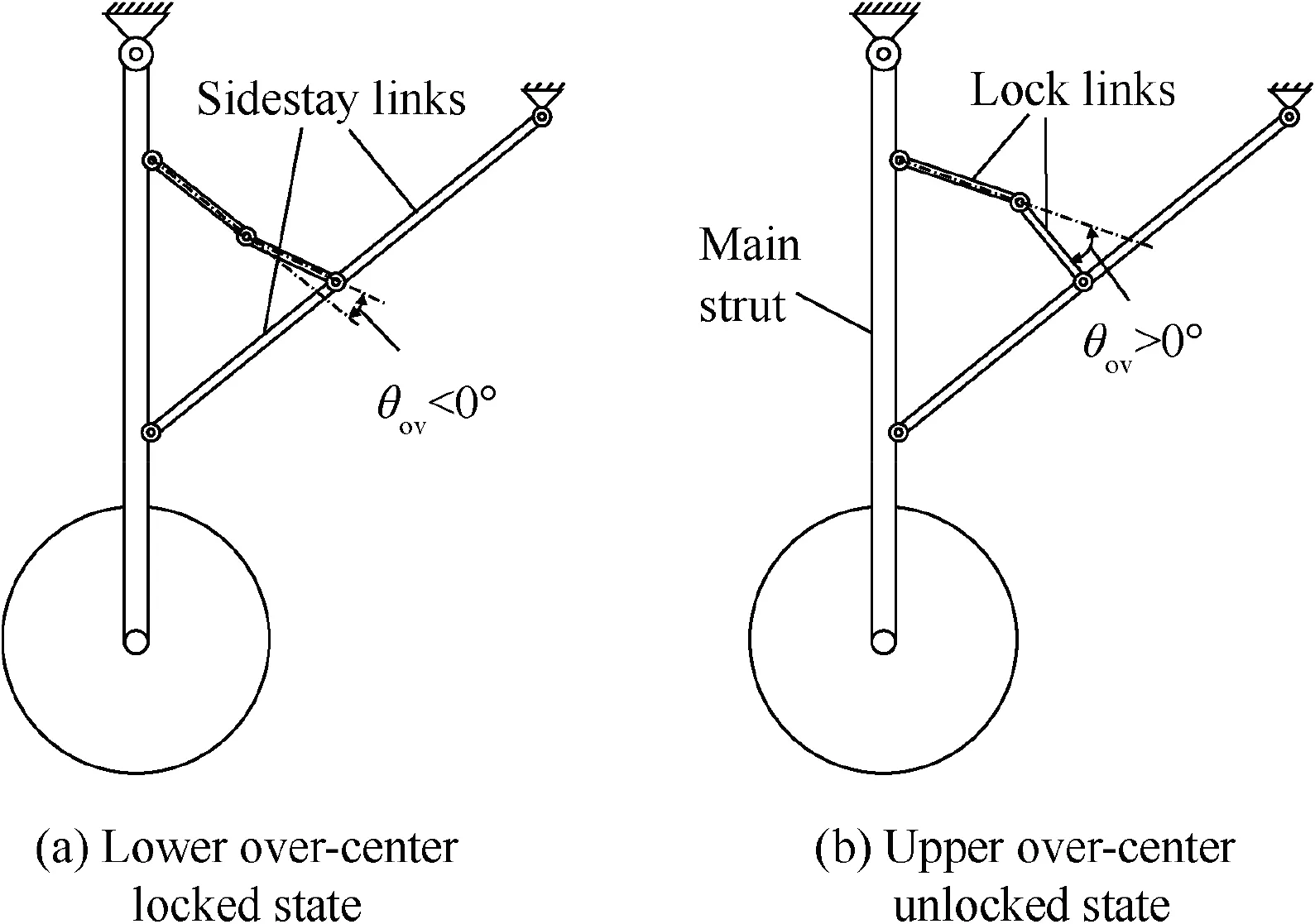
Fig. 1 Locking process of a single-sidestay landing gear.
For a fully rigid model, the mechanism motions on two sides must be completely coordinated, and the dimensional sensitivity is very high. This places extremely high requirements on the machining and assembly precision of landing gears, which cannot be met by real landing gears’ machining processes. Theoretical analyses have also revealed that under a fully rigid condition, complete locking of DSS landing gears is almost impossible. In actual practices, however, the landing gears can be completely locked under certain conditions.Such differences between existing theoretical analyses and actual situations primarily lie in the structural clearance and deformation, which can offset and weaken the sensitivity problem of landing gear locking. Due to space limitations, this paper focuses only on the effects of clearance,while the deformation effects will be discussed in subsequent research. Clearance is caused by diversified factors, such as the fit clearance, manufacturing and assembly errors,as well as friction and wear.Machinery system dynamics with clearances has been developed for many years, and a variety of theories have been formed,including the continuous contact models,the classical collision modelsand the continuous contact force models.The continuous contact force models, in particular, can solve the collision force during the system motion.Besides, they can also be easily integrated into the dynamic equations of multi-body systems.
For a progressive research of the synchronous locking performance of DSS landing gears, this paper separately constructs the bifurcation analysis model of an ideallyarticulated landing gear system and that considering clearance,with which investigation is made into the synchronous locking performance, and the reasons for incomplete locking are analyzed. The main contents of this article are as follows: In Section 2, a bifurcation analysis model of an ideally-articulated landing gear system is built,and after analyzing its bifurcation characteristics, the fundamental mechanism of synchronous locking is clarified in Section 3.The influence of joint clearance is considered into the study in Section 4, which finds that the addition of clearance is conducive to the complete locking of landing gear, and that the synchronous locking is closely correlated with the number of bifurcation points in the bifurcation diagrams under particular states. In Section 5, the effects of rod lengths on the synchronous locking are analyzed after considering the joint clearance, and on the premise of synchronous locking, the feasible region of rod length parameters is obtained,which agrees well with the test results.Application of this method is effective in addressing the coordinated locking problem of two sidestay links at the initial design stage of landing gears, which is of great significance to component design and can provide the powerful guidance for the design and analysis of DSS landing gears.
2. Bifurcation analysis and modeling of a DSS landing gear
2.1. Analytical object
DSS landing gear systems have more complicated motion than the planar systems. Fig. 2 presents a certain 3D retractable DSS landing gear, which comprises a main strut, a fore sidestay system, an aft sidestay system and wheels. Each sidestay system is composed of sidestay links, lock links, sidestay nodes, a lock node, locking springs and an unlock actuator.Apart from fulfilling 3D retraction function, the landing gear also needs to achieve coordinated motion between two sidestay systems and the main strut, without restricting each other. In the figure, all components are rigid, which are connected via ideal planar hinges.
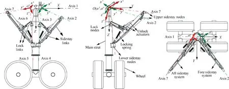
Fig. 2 Schematic of a certain DSS landing gear.
To fulfill the 3D retraction function of the DSS landing gear, the rotation axis of main strut (axis 1 in Fig. 2), the axis of fore lock node (axis 3) and the axes of upper and lower nodes of fore sidestay links (axes 2 and 4) must intersect at one point (point o).In the meantime, the rotation axis of main strut (axis 1), the axis of aft lock node (axis 6) and the axes of upper and lower nodes of aft sidestay links (axes 7 and 5) must also intersect at one point (point o). In this way,the two sidestay systems can move within their respective planes. During the gear’s extension and retraction operations,the main strut rotates along the axis 1, while the fore and aft sidestay systems not only perform the folding motion,but also rotate around specific axes(axis 2 for the fore sidestay system,and axis 7 for the aft sidestay system).During retraction of the landing gear, the fore and aft unlock actuators are needed to fold up and unlock the lock links,while the retraction actuator can be engaged to let the main strut rotate around the axis 1.Accordingly, the fore and aft sidestay systems move to the retracted position and the locking box is locked.During extension of the landing gear, after locking box unlocking the retraction actuator pushes the landing gear to enable the slow extension of main strut around the axis 1. When approaching the lower locking position,the lock links jump from the upper to the lower over-center state through the tension of locking springs, thereby completing the locking process.
2.2. Coordinate transformation
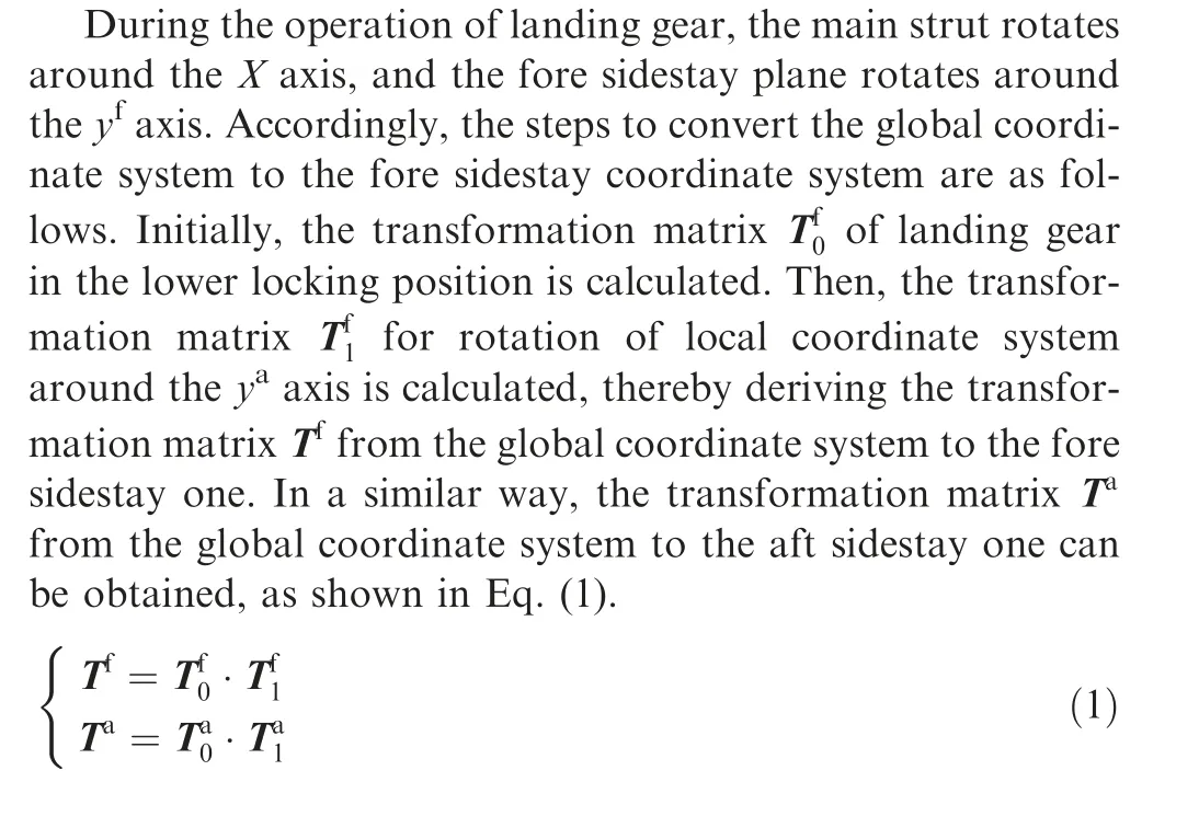
Since the rotation plane of main strut and the motion planes of fore and aft sidestay systems are not co-planar, direct solving in the same coordinate system is quite difficult. It is found through analysis that during the extension and retraction of landing gear, the fore sidestay system moves within the same plane, while the aft moves within another plane.Hence,the kinematic model can be simplified by establishing different coordinate systems that characterize the motion of main strut,fore sidestay system and aft sidestay system, where the data exchange among coordinate systems is realized through coordinate transformation.
Coordinate systems are established as shown in Fig. 2. In the global coordinate system O-XYZ, the origin O represents the intersection between the main strut and axis 1; the X axis represents the direction of axis 1; the Z axis is parallel to the direction of gravity; and the direction of Y axis is determined by the right-hand rule. In the local coordinate system o-xyzof fore sidestay system,the origin ois the intersection point of four axes (axes1-4) for the fore sidestay system; the yaxis is the direction of axis 2;the zaxis is perpendicular to the yaxis within the fore sidestay plane; and the direction of xaxis is determined by the right-hand rule. Similarly, local coordinate system o-xyzof aft sidestay system can be obtained.
2.3. Motion constraint equations

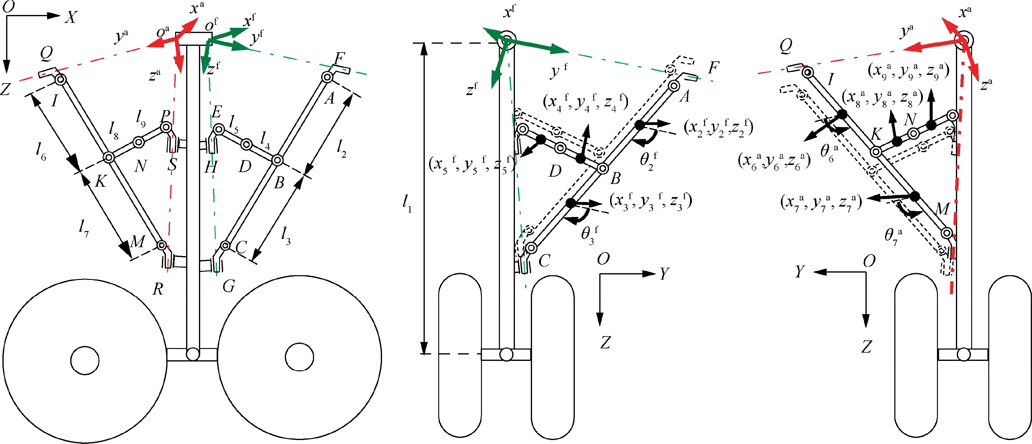
Fig. 3 Schematic of landing gear system.

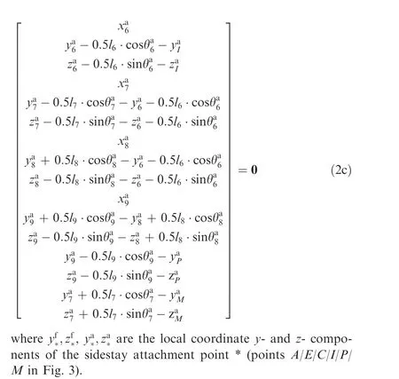
2.4. Force and moment equilibrium equations
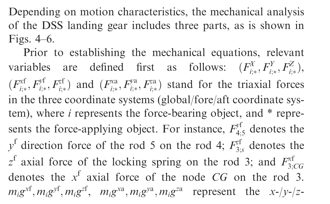
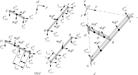
Fig. 4 Mechanical equilibrium of fore sidestay system in the fore sidestay coordinate system.
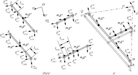
Fig. 5 Mechanical equilibrium of aft sidestay system in the aft sidestay coordinate system.
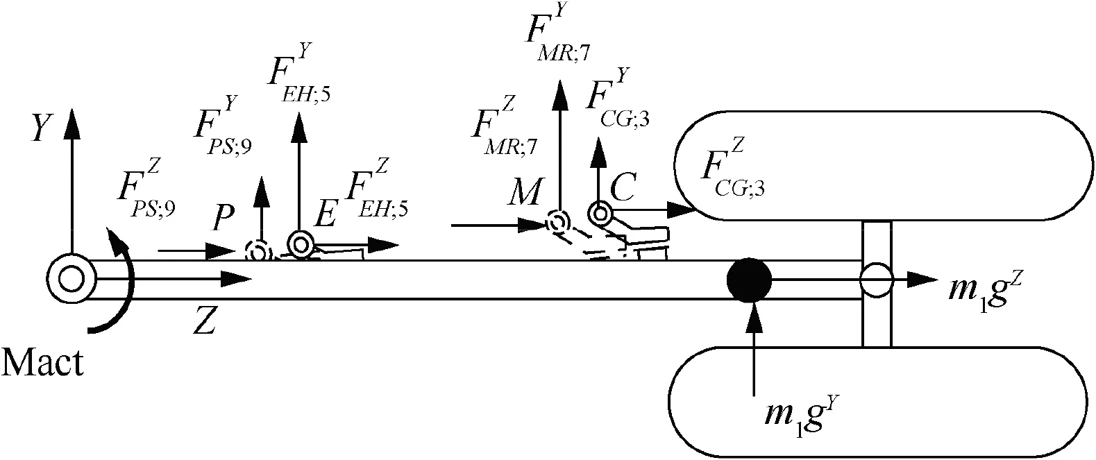
Fig. 6 Mechanical equilibrium of main strut in the global coordinate system.
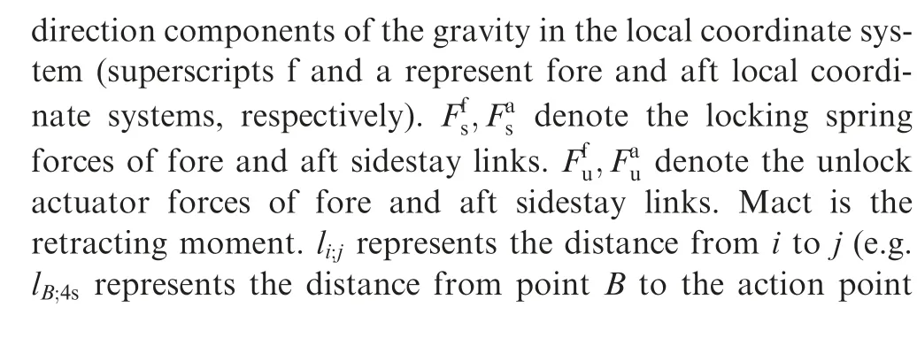
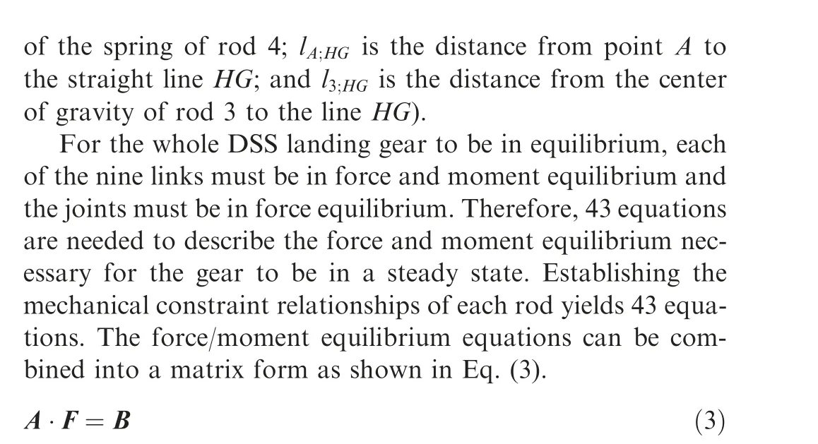
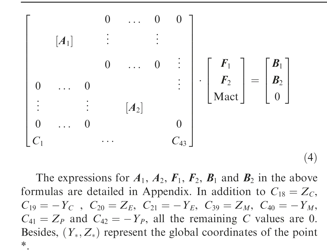
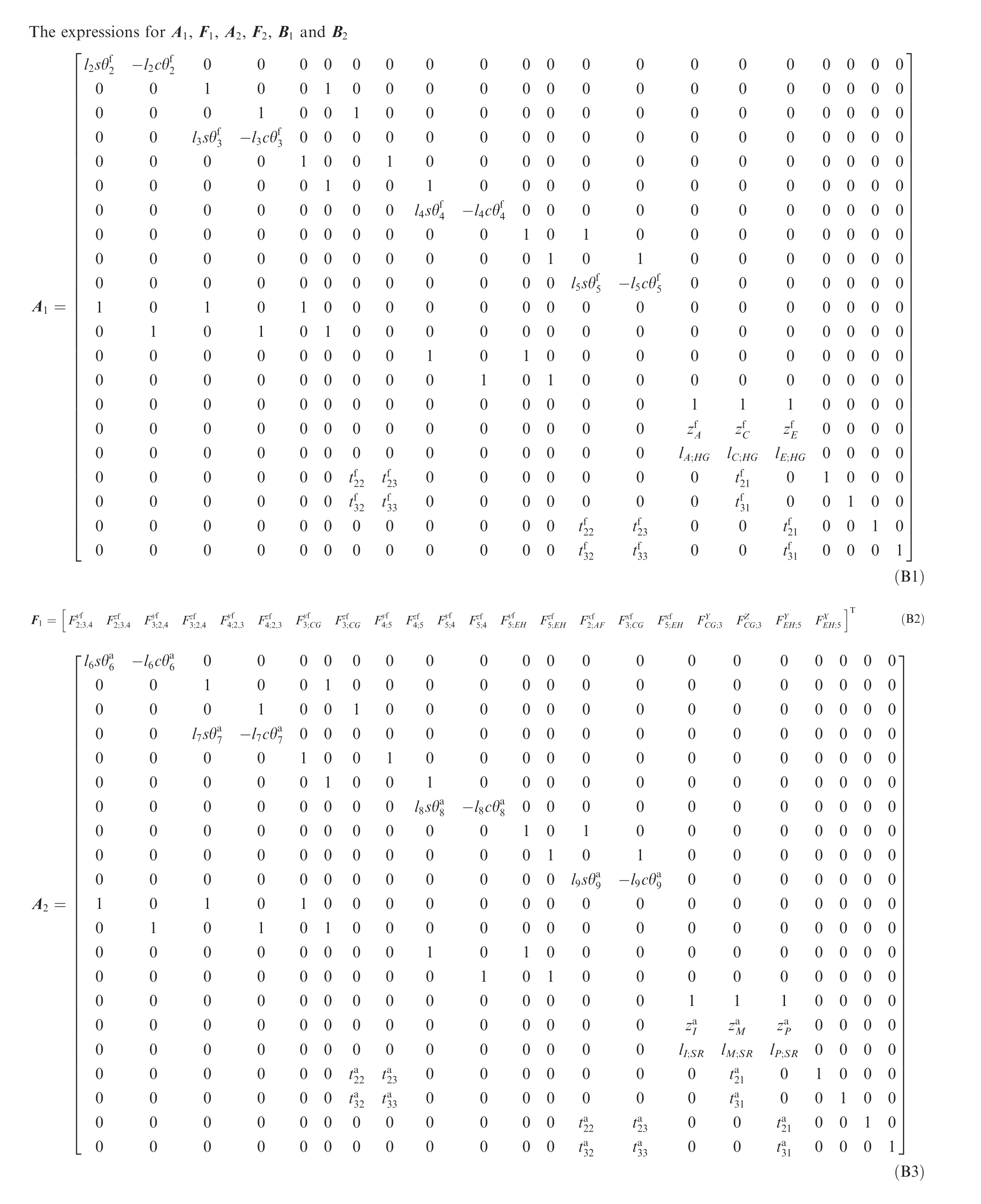
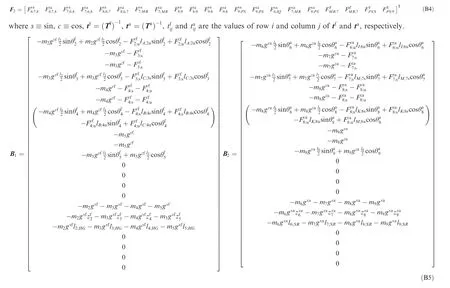
here A is a 43×43 matrix,and rank(A)=43.The vector of nternal forces F can be calculated by computing A∙B,here Ais the inverse matrix of A. Rather than presenting matrix A as a single, sparse matrix, the elements within A an be grouped such that the force coefficients from the global,ore,and aft constraint equations become submatrices in A.In his way, Eq. (3) can be written as,
3. Bifurcation analysis on synchronous locking of ideallyarticulated DSS landing gear
3.1. Analysis of locked states
As suggested in Ref. 10, to achieve complete locking of a single-sidestay landing gear, the lock links must jump from the upper over-center state to the lower over-center state. In the case of a DSS landing gear, the lock links on both sides must reach a lower over-center state simultaneously, in order to achieve synchronous locking of sidestay links. Depending on the position of lock links, four different states can be encountered during the locking of DSS landing gear as shown in Fig. 7(a)–(d). Regarding the sidestay links, the gray lines represent the fore sidestay links and the black lines represent the aft sidestay links. Table 1 details their corresponding motion states. In Fig. 7(a), the fore and aft lock links are synchronously in the upper over-center state, which is the completely unlocked state (UU). In Fig. 7(b), the fore and aft lock links are synchronously in the lower over-center state,which is the completely locked state (DD). Fig. 7(c) and (b)depict incompletely locked states (UD, DU), where lock links on one side are in the upper over-center state while lock links on the other side are in the lower over-center state
The locking of landing gear is a switching process between different states described in Fig. 7. Movement from the initial state UU to the state DD indicates that the landing gear is completely locked, while movement from the state UU to the state UD or DU indicates that the landing gear cannot be completely locked.During the complete locking process of the DSS landing gear, the switching between various states in Fig. 7 must satisfy certain geometric constraint relationships. The motion constraint equations can be continued numerically to analyze these relationships,and the results are shown in Fig.8.
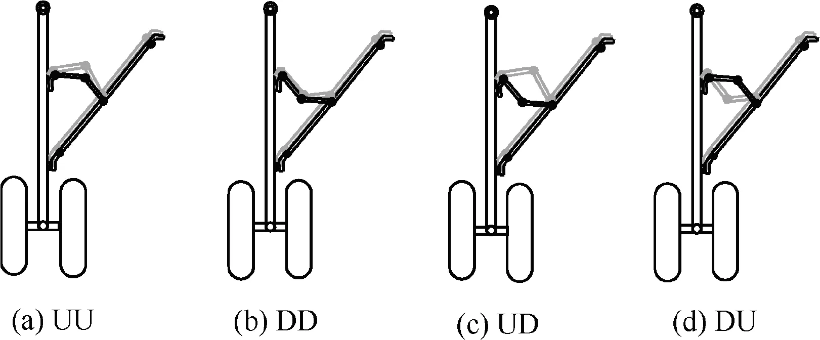
Fig. 7 Different locked states of the DSS landing gear.
Fig. 8 depicts the relationships between over-center angles and the retraction angle,where the gray lines represent the fore lock links and the black lines represent the aft lock links. The ordinate θdenotes the difference between angles of two lock links, which is θ=θ-θfor the fore lock links and is θ=θ-θfor the aft lock links. During complete locking of DSS landing gear, all lock links should be in the lower over-center state, that is, θ< 0, e.g. θ=-2(point C in the Fig. 8). The position corresponding to point A is the farthest position of landing gear extension. At this time, Θis the smallest, and the upper and lower sidestay links are collinear. Meanwhile, point B is the position of θ=0°, which means the upper and lower lock links are collinear at this point. To achieve complete locking, the fore and aft sidestay systems must synchronously pass through the points A and B, otherwise the lock links on one side cannot reach the point C due to the limitation of retraction angle Θ. Thus, the geometric constraint relationships must satisfy the following conditions:(A)when the upper and lower sidestay links in the fore sidestay system are collinear, the upper and lower sidestay links in the aft sidestay system should be also collinear, as shown in Fig. 9(b) (Z1); and (B) when the upper and lower lock links in the fore sidestay system are collinear, the upper and lower lock links in the aft sidestay system should be also collinear, as shown in Fig. 9(c) (Z2). Accordingly, the locking of DSS landing gear can be described by the following process:an initial movement from the completely unlocked state UU to the intermediate state Z1(corresponding to point A in Fig.8),a subsequent movement from the intermediate state Z1 to the intermediate state Z2(corresponding to Point B in Fig.8),and a final movement from the intermediate state Z2 to the lower over-center state DD which is precisely the completely locked state of DSS landing gear, as shown in Fig. 9.
3.2. Failure analysis on synchronous locking of ideallyarticulated DSS landing gear
Under ideal articulation, the quasi-static equations of DSS landing gear can be numerically continued in different states,and their bifurcation curves are obtained as shown in Fig. 10. Fig. 10(a), (b), (c) and (d) correspond to the bifurcation curves in UU/DD/UD/DU state, respectively. Their state relationships have a one-to-one correspondence with Fig. 7 and Table 1.In Fig.10,the solid lines represent the stable equilibrium solutions;the dashed lines represent the unstable equilibrium solutions; the gray lines indicate the fore sidestay system; and the black lines indicate the aft sidestay system.The intermediate states (Z1 and Z2) in locking process correspond to the gray and black dot-dash lines in Fig. 10. The black dot-dash lines in various subfigures all indicate the same state, while the state switching between subfigures must be implemented via the intermediate states. Although the intermediate state Z2 has no equilibrium solution, it is passed through during the locking movement.
The synchronous locking performance of DSS landing gear can be in ideally-articulated circumstances analyzed based on Fig. 10 in combination with Figs. 7 and 9.

Table 1 States of the DSS landing gear.
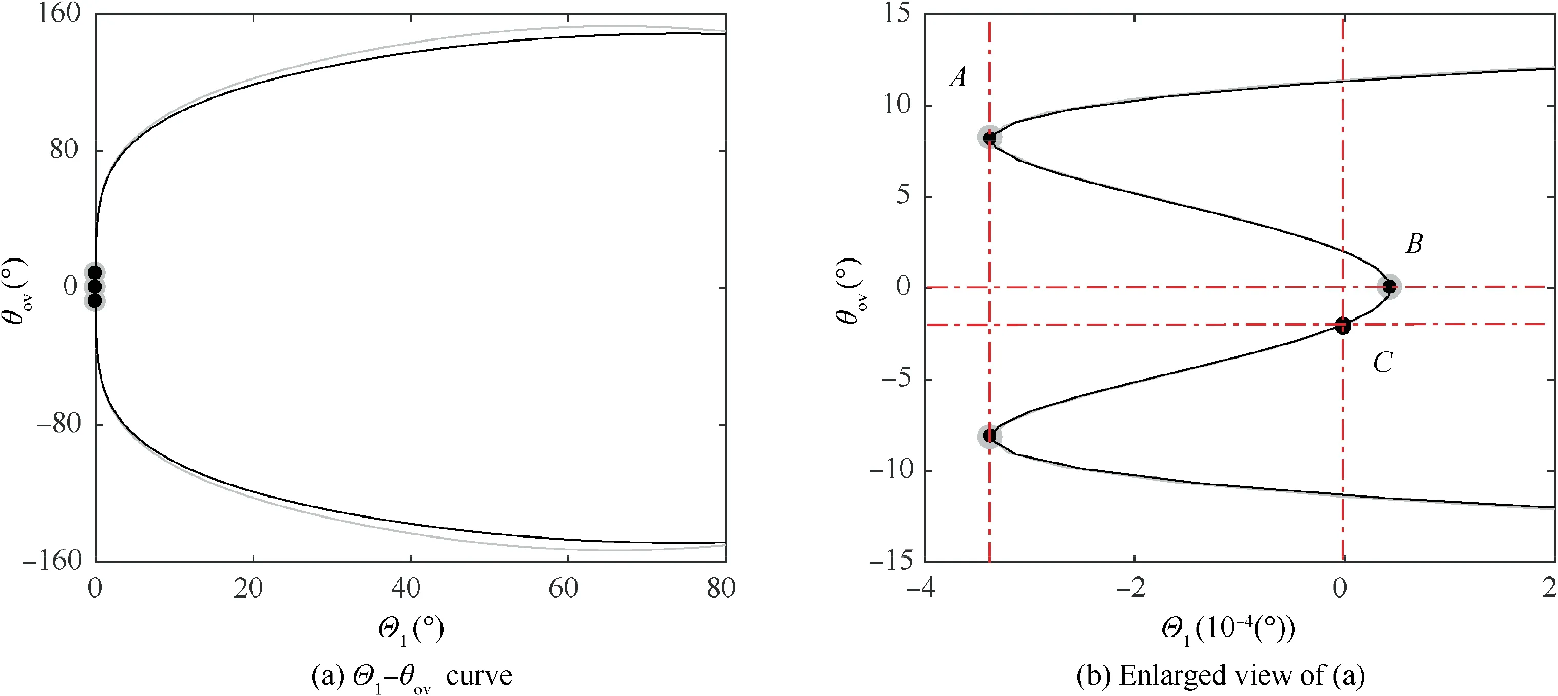
Fig. 8 Variations of lock link over-center angles with the DSS landing gear retraction angle.
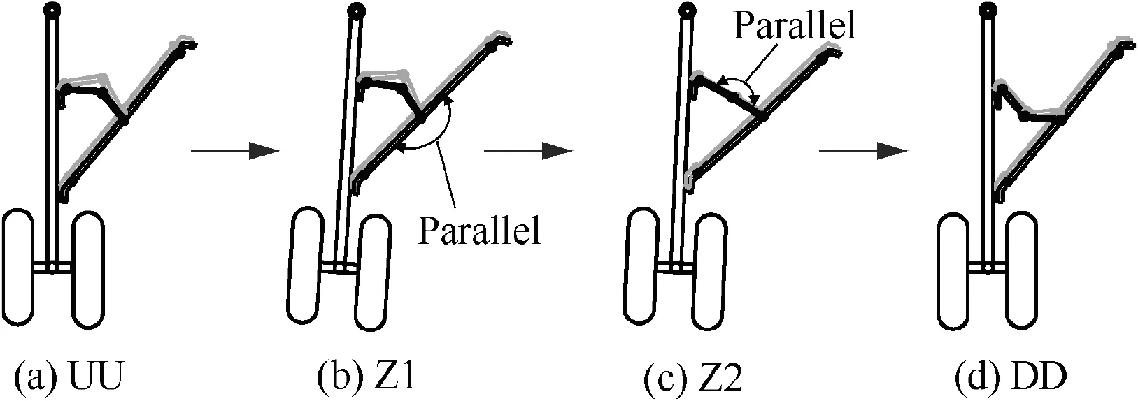
Fig. 9 Complete locking process of the DSS landing gear.
(1) In Fig. 10(a), the lock links on both sides are in the upper over-center position, which is the initial state (UU). A saddle-node bifurcation occurs at SN, and the points on its right side converge to the stable equilibrium solutions along the arrow directions. When the external load is less than the load corresponding to point SN, the DSS landing gear has no equilibrium solution in this state, that is, the equilibrium solutions do not exist in state UU.In other words,the landing gear system will switch to another stable equilibrium state.It is clear from the foregoing analysis that when the landing gear moves from state UU to another equilibrium state, it inevitably passes through the intermediate states Z1 and Z2. During design, if the geometric constraints of the landing gear system disallow its movement to an intermediate state (Section 3.1),incomplete locking will be unavoidable.Only when the specific geometric constraints are satisfied,the system can move to the intermediate states Z1 and Z2 sequentially, and finally switch to another stable equilibrium state.
(2) In Fig. 10(b), the lock links on both sides are in the lower over-center position, which is the completely locked state (DD). There are two saddle-node bifurcations on the curves, and the points in state Z2 are still attracted by the stable curves, which eventually converge to the solid-line curves along the arrow directions to accomplish complete locking process of the DSS landing gear.In other words,the landing gear may move from the state UU to the state DD, thus allowing its complete locking.
(3) In Fig. 10(c), the fore lock links are in the upper overcenter position and the aft lock links are in the lower overcenter position, which describe the incompletely locked state(UD). A saddle-node bifurcation occurs at SN.After moving to state Z2, the motion of the mechanism is repelled by the dashed lines near state Z2 since they are unstable equilibrium solutions. The system will stabilize in the intermediate state and cannot be attracted by the stable solid lines by crossing the unstable dashed lines,suggesting that the landing gear does not move to the state UD.
(4) In Fig. 10(d), the fore lock links are in the lower overcenter position and the aft lock links are in the upper overcenter position, which also describe the incompletely locked state (DU). The curves near state Z2 are stable, so that the motion of DSS landing gear is attracted by them following the system movement to the intermediate state Z2. Under this circumstance, the system cannot be completely locked on one side. From Fig. 10(e) showing an appropriately enlarged view of the coordinates in Fig. 10(d), it is clear that a new bifurcation point SNoccurs at greater Mact, which leads to the appearance of new stable equilibrium curves near state Z2.Accordingly, the landing gear is attracted by the new stable equilibrium solutions during locking, thus resulting in incomplete locking.In other words,the landing gear may move from the state UU to the state DU, thus disallowing its complete locking.
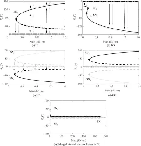
Fig. 10 Bifurcation curves of retracting moments in different states.
To sum up, under ideal articulation, the DSS landing gear may be in either state DD or DU during locking. In the state DU, the stable curves are closer to the intermediate state Z2 than in the state DD, so that the movement of landing gear system is more likely to be attracted and stabilize to the curves of state DU,thus resulting in incomplete locking of the landing gear. This is also the fundamental reason why the fully-rigid DSS landing gear cannot be completely locked under ideal articulation.
4. Bifurcation analysis on synchronous locking of DSS landing gear considering clearance
4.1. Modeling of articulated kinematic pair with clearance
Despite the presence of incomplete locking of landing gear under ideal articulation, in reality, the articulated joints of landing gear are not ideal, which presents certain clearance and flexibility.In this section,a model of articulated DSS landing gear with clearance is built for locking performance analysis. Fig. 11 depicts the clearance modeling process.
After consideration of clearance, the size of clearance c is expressed as c=R-R, where R,Rdenote the joint radii of link i and j,respectively.The eccentricity value e is expressed as

When δ>0,the articulated kinematic pair of the two links is in the separated state; δ=0 indicates the moment when the joints of the two links contact or separate;and when δ<0,the kinematic pair is in the collision state.
Since equilibrium solution is analyzed herein, the speed term in equations is zero and the effect of damping can be negligible. Accordingly, the collision contact force model can be constructed based on the Hertz model(Eq. (5)). Joint clearance is introduced into the joints C and M in Fig. 3, and the interaction force between link i and j can be described as,

Fig. 11 Modeling of articulated kinematic pair with clearance.

where E,γ denote the elastic modulus and Poisson’s ratio,respectively.
4.2. Bifurcation analysis of locking performance of articulated DSS landing gear with clearance
Under different states of lock links on both sides,when the size of clearance joints C and M is 0.2 mm, the quasi-static equations of DSS landing gear can be numerically continued to obtain bifurcation curves as shown in Fig. 12.
Comparison of Figs. 10 and 12 can find that the curves of states UU and UD are similar in both figures.Two new bifurcation points(SNand SN)appear in the curve of state DD in Fig. 12, which can be attributed to the change in the collision contact point of the clearance,but the appearance of these two points does not change the stability of curves near the intermediate state Z2.The points on Z2 remain attracted by the stable solid lines in state DD.In the curves of state DU in Fig.12,the bifurcation point SNdisappears, which leads to the absence of stable curves near the intermediate state Z2 in Fig. 10,thus turning the curves near Z2 into unstable equilibrium solutions.The movement of DSS landing gear will be repelled by the unstable dashed lines, and the system cannot move to the stable solid lines in state DU due to its inability to cross the unstable dashed lines. This suggests that in the case of considering joint clearance,the DSS landing gear will only stop in the state DD while cannot move to the state UD or DU during the locking process, thereby allowing its complete locking.
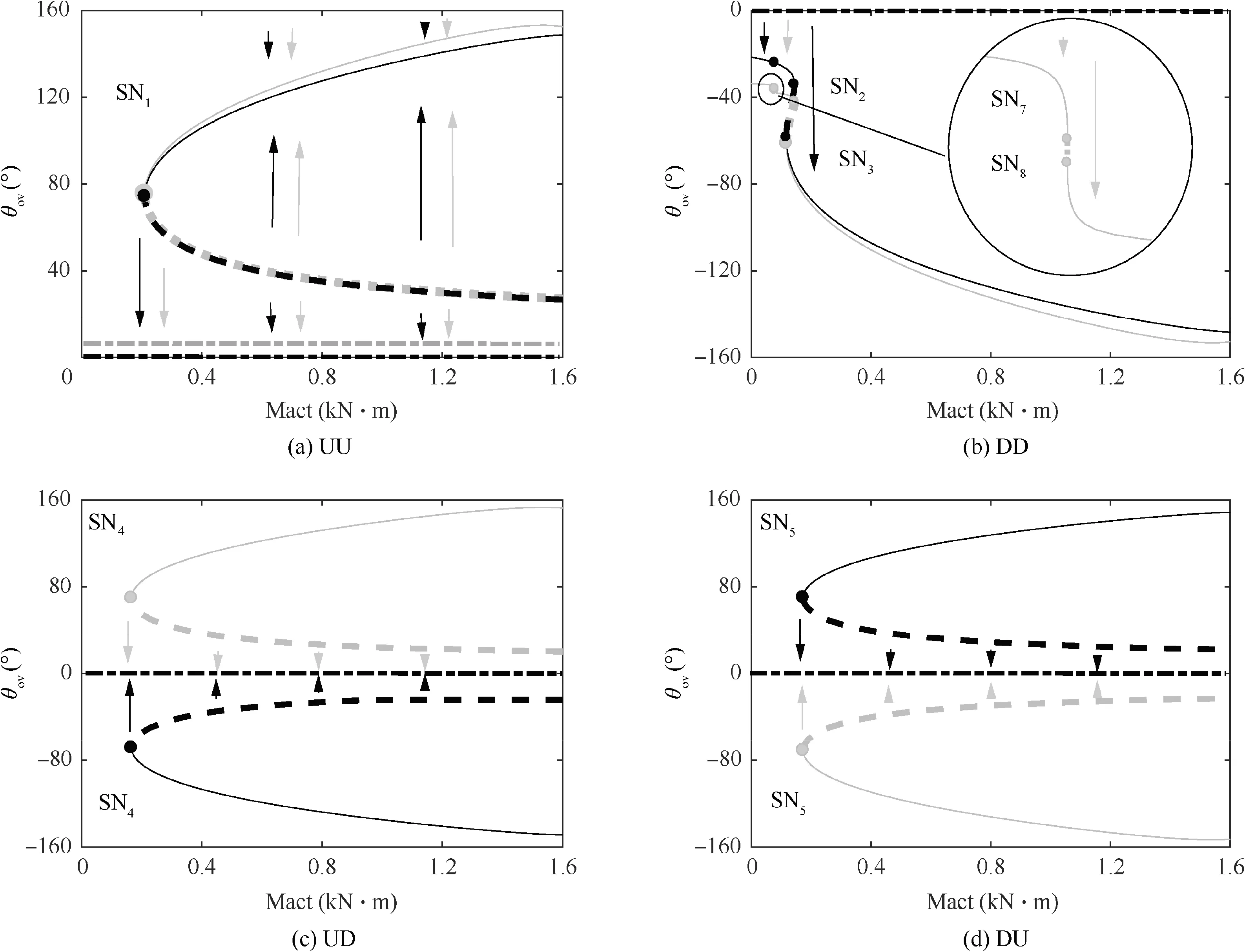
Fig. 12 Bifurcation curves of retracting moments considering clearance in different states.
4.3. Relationships between coordinated locking and bifurcation points
According to the analysis in Sections 3.2 and 4.2, to achieve smooth and complete locking of DSS landing gear, there should be no stable curves near the intermediate state Z2(θ=0°) in the states UD and DU. Since bifurcation points are directly and closely correlated with the stability of curves,it is very important to analyze the relationships between bifurcation points and coordinated locking to determine whether DSS landing gear can be locked successfully.
Fig. 13 depicts the locking condition of DSS landing gear with different number of bifurcation points.Given the similarities of bifurcation curves of fore and aft lock links, only the curves of aft lock links are presented. In Fig. 13(a), there are four bifurcation points, and the curves near the intermediate state Z2 are stable,which means that the motion of DSS landing gear will be attracted to the stable curves,thus disallowing complete locking of the system. In Fig. 13(b), there are three bifurcation points, and the curves near the intermediate state Z2 are unstable, so that the motion will be repelled by the unstable curves, thus allowing complete locking of DSS landing gear. Based on the above analysis, we can generalize more universal conclusions. If the number of bifurcation points is even,the DSS landing gear cannot be completely locked,while if the number is odd, the system can be completely locked.
4.4. Effect of the size of clearance c on DSS landing gear’s locking performance
After considering the effect of clearance, DSS landing gear can be completely locked. Complete locking means that the bifurcation curves near the intermediate state Z2 in states UD and DU must be unstable, and that the number of bifurcation points must be odd. In this section, the effects of different sizes of clearance on the system’s locking performance are analyzed, where such effects on the states UD and DU are considered. Fig. 14 displays the results, with Fig. 14(a) and (b) being the bifurcation curves of states UD and DU, respectively.
In Fig. 14, the continued results corresponding to c=1 mm,0.5 mm and 0.2 mm are presented from top to bottom. As is clear, the bifurcation curves for different sizes of clearance are fundamentally identical in trend, and there is always only one bifurcation point.In other words,the changes in clearance size do not affect the synchronous locking performance of the system. Although the addition of joint clearance facilitates the complete locking of dual sidestay links,an excessively large clearance will increase structural wear and shorten the service life of links. Therefore, an adequate size of clearance should be selected.
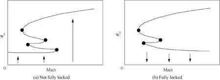
Fig. 13 Diagram of relationships between the number of bifurcation points and whether DSS landing gear is fully locked.
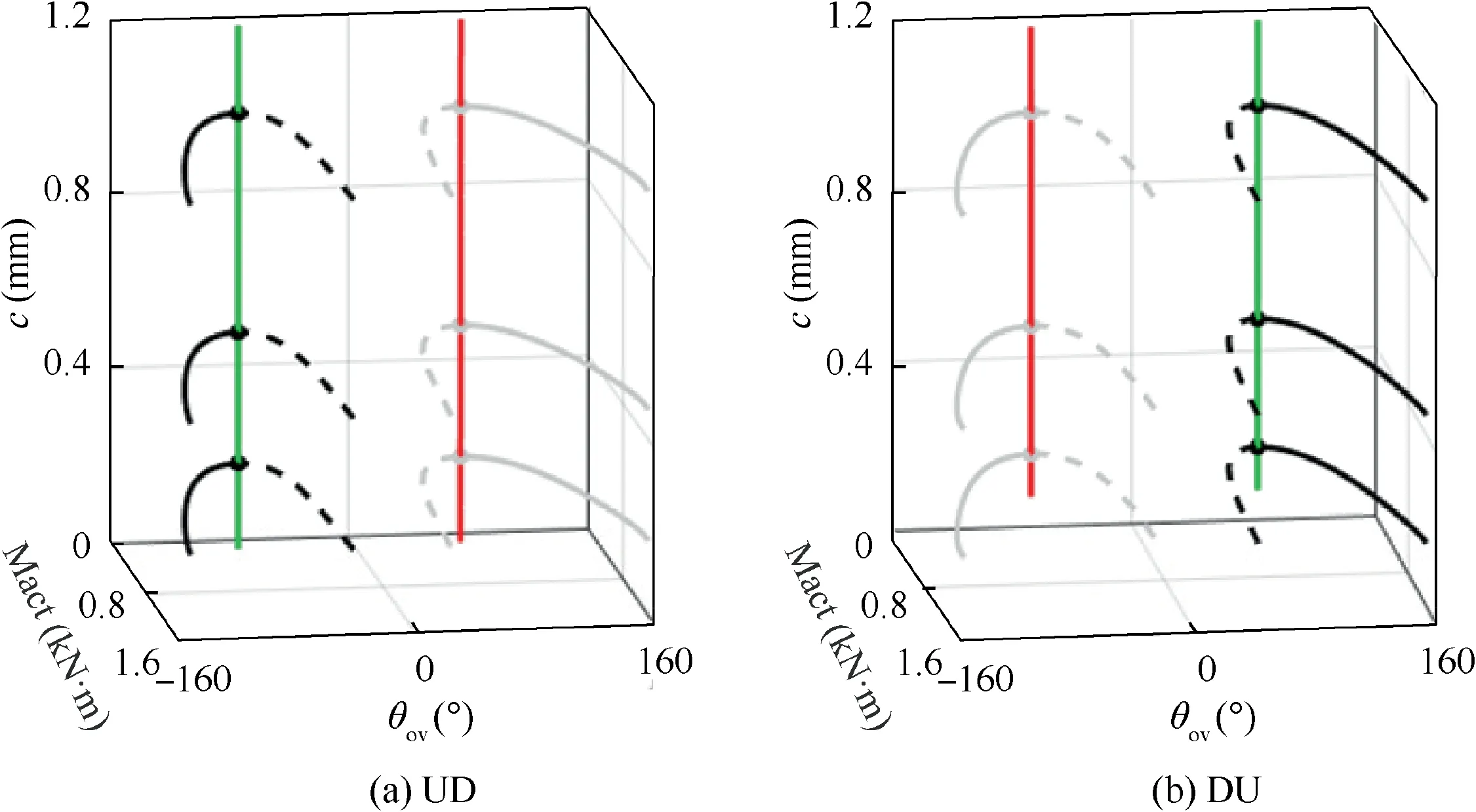
Fig. 14 Effects of different sizes of clearance on different states.
5. Design of rod lengths for DSS landing gear considering joint clearance
5.1. Effect analysis of single rod length parameters
The theoretical results under ideal articulation demonstrate that it is impossible to achieve complete locking of DSS landing gear. In reality, the synchronous locking of DSS landing gear is slightly less sensitive to the structural dimension due to the presence of clearance.Meanwhile,rod lengths deviation need to satisfy reasonable range requirements, which are critical for the synchronous locking of the system. In this section,the effects of DSS landing gear’s rod lengths on its synchronous locking performance are analyzed after considering joint clearance, so as to design appropriate rod lengths for DSS landing gear on the premise of complete locking. It is clear from the foregoing analysis that to achieve smooth and complete locking, the number of bifurcation points in states UD and DU must be odd.Thus,by analyzing the effects of different rod lengths on the number of bifurcation points,we can further analyze the locking condition of the DSS landing gear system.
For the state DU, a second parameter (for example with rod length l)can be introduced through continuation starting from the bifurcation point SNin one-parameter plane,thereby obtaining the two-parameter bifurcation curves as shown in Fig. 15.
The red and green lines in Fig. 15 represent the twoparameter bifurcation curves of the fore and aft sidestay systems, respectively, which exhibit exactly the same trends. The red lines (green lines) are a set of variations of all bifurcation points with the rod length l.With the increase in l,the number of bifurcation points changes accordingly,and the stability of the equilibrium curves near the intermediate state Z2 also undergoes changes during this period. For ease of analysis,the curves in Fig. 15 are subjected to projection to obtain Fig. 16.
The Fig. 16(a) is similar to Fig. 12(d), which suggests that the DSS landing gear cannot move to state DU during the locking process, while in Fig. 16(b) and (c), there are four bifurcation points, and the curves near the intermediate state Z2 are stable. In other words, the points at θ=0° will be attracted by the stable curves, and the system may not be locked completely. Fig. 16(d) illustrates the projection of loci of bifurcation points (red and green lines) in Mact-lplane.There are 4 bifurcation points when l> 430∙46 mm, and are 1,3 or 5 bifurcation points when l< 430∙46 mm.Hence,it can be seen that in order to ensure excellent locking performance of DSS landing gear, the rod length lshould be less than 430.46 mm.
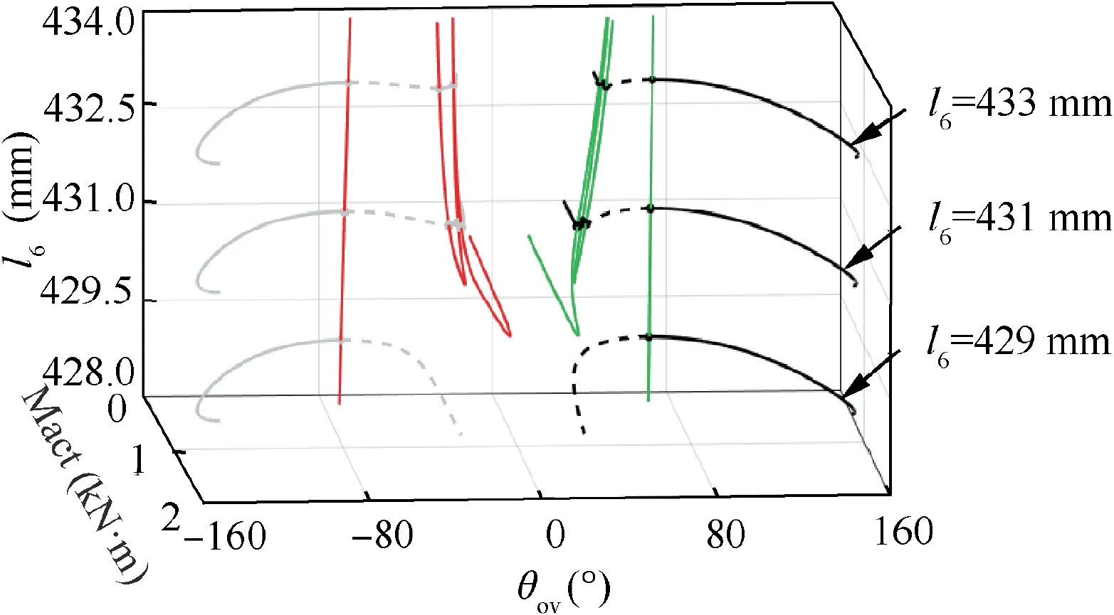
Fig. 15 Variations of bifurcation points with l6 in state DU.
The two-parameter bifurcation curves and their projections for state UD can be obtained in a similar way, as shown in Figs. 17 and 18, respectively.
It can be seen from these figures that the bifurcation curves of state UD and state DU are very similar,and that the loci of bifurcation points in the two states show a mirror symmetry relationship. The critical rod length lis also very close. It is not difficult to find that in order to avoid synchronous locking failure of DSS landing gear due to its movement to state UD,lmust be above 429.54 mm.
To sum up,when the size of clearance at joints C and M is 0.2 mm, rod length lin range 429.54 mm–430.46 mm can ensure complete locking of the DSS landing gear. The effects of variations in other rod lengths on the system’s locking performance can be analyzed in a similar way, which will not be detailed herein.
5.2. Effect analysis of double rod length parameters
From Fig.13,it is clear that for the DSS landing gear system,there is a point at which Mact=0 on the bifurcation curves of lock links when the number of bifurcation points is even, so that the system cannot be completely locked. When the number of bifurcation points is odd, the curves have no point at which Mact=0, thus allowing the complete locking of DSS landing gear.Hence,the design of rod lengths for DSS landing gear can be accomplished by regarding Mact=0 as a fixed variable and the rod length of a link as a control parameter,thereby obtaining bifurcation curves in one-parameter plane.Subsequently, two-parameter bifurcation curves can be obtained by introducing another rod length parameter through unfolding starting from the bifurcation points in oneparameter plane. In this section, the sidestay link length land the lock link length lis used as the second parameters,and the bifurcation curves are shown in Figs. 19 and 20.
Fig.19 depicts the two-parameter bifurcation curves taking land las control parameters, where Fig. 19(a) is a 3D view,and Fig. 19(b) and (c) are the projections of corresponding curves in θ-lplane and l-lplane, respectively. For ease of analysis, only the curves of lock links on one side are displayed. To be specific, the gray lines represent the bifurcation curves of fore lock links in UD state, whereas the black lines represent the bifurcation curves of aft lock links in DU state.The solid lines represent stable points,and the dotted lines represent unstable points. The system will not reach unstable curves during motion. Besides, the red and green lines represent the loci of bifurcation points SNand SNvarying with land l.
From the Fig. 19(b), it is clear that when lis less than the value corresponding to SN(429.54 mm)or is greater than the value corresponding to SN(430.46 mm), there is a point at which Mact=0 on the gray or black line.That is,it is difficult to achieve the complete locking of DSS landing gear in these circumstances. While when lis between SNand SN, the curves have no point at which Mact=0. In other words, the number of bifurcation points on curves is odd, which implies the successful locking of DSS landing gear. Hence, the value of lshould be assigned between SNand SN, i.e.l∊(429∙54 mm, 430∙46 mm), which agrees with the result of the single rod length parameter analysis.
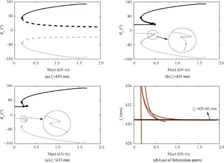
Fig. 16 Projections of (a)-(c) bifurcation curves with different l6 and (d) loci of bifurcation points for varying l6 in state DU.
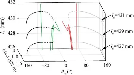
Fig. 17 Variations of bifurcation points with l6 in state UD.
A second parameter lcan be introduced through continuation along the bifurcation points SNand SNthereby obtaining the curves of bifurcation points along l(red and green lines). Within the area enclosed by these two lines, there is no point at which Mact=0, suggesting that any parameter value within this area can achieve complete locking of the landing gear. Thus, the l-larea enclosed by red and green lines is precisely the feasible region for complete locking.Once the value of a parameter is determined (e.g. l= 340 mm)during analysis, the value range of another parameter (such as l) can be obtained intuitively, as shown by the dotted lines in Fig. 19(c).
Fig. 20 presents the two-parameter bifurcation curves taking the sidestay link length land the lock link length las control parameters.The feasible region of the value of land lin this case can also be obtained (as shown in Fig. 20(c)). But compared to Fig. 19, the difference is that when lis a fixed value (e.g. l= 430 mm), the value of lhas a larger range.This suggests that the lengths of sidestay links have a comparatively greater effect on the coordinated locking of DSS landing gear than the lengths of lock links. Nevertheless, the lengths of lock links should not be excessively long, since excessive lengths can easily lead to locking failure of lock links on one side due to the effect of lock link stops.Generally,their lengths should be selected within a ±10 mm range.
5.3. Test results
In order to verify the numerical results of locking performance with different rod lengths, a set of retraction tests on a DSS landing gear physical prototype were carried out. During the test,the initial position of the landing gear was in the retracted and locked state (Θ=80), and then the main strut was slowly lowered under the drive of a motor. The results are shown in Figs.21 and 22.In Fig.21,the red and green curves represent the test results in the case of l=430 mm and l=432 mm, respectively; and the blue curves represent the bifurcation results in the case of l=430 mm. Through comparison, it is found that the test results and the numerical results are basically consistent in the stable branches. Near the bifurcation point SN, the trajectory cannot continue to move along the unstable branches,and the landing gear jumps and locks at this time.When l=430 mm,the test results show that lock links on both sides can reach the locked state(θ<0°), as shown in Fig. 22(a). In contrast, as shown in
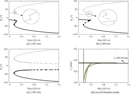
Fig. 18 Projections of (a)-(c) bifurcation curves with different l6 and (d) loci of bifurcation points for varying l6 in state UD.

Fig. 19 Two-parameter bifurcation curves with sidestay link lengths l6 and l7 as control parameters.

Fig. 20 Two-parameter bifurcation curves with sidestay link length l6 and lock link length l8 as control parameters.
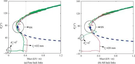
Fig. 21 Test results of the DSS landing gear.
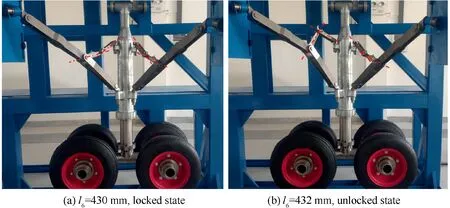
Fig. 22 Locked and unlocked states of the DSS landing gear.

6. Conclusions
(1) Detailed discussion is made concerning the reasons for incomplete locking of dual-sidestay (DSS) landing gear system under ideal articulation. A close correlation is found between whether the landing gear can be completely locked and whether the bifurcation curves near the intermediate state(the over-center angle of lock links is zero) is stable in various states. During locking motion,since the equilibrium curves of fore and aft lock links near the intermediate state are stable, the motion of DSS landing gear can be easily attracted to these stable curves, thereby resulting in incomplete locking.
(2) By introducing hole–axis clearance into the model of fully-rigid ideal articulation DSS landing gear, an improved model considering joint clearance for analyzing synchronous locking performance of DSS landing gear is built.The developed model allows accurate analysis of the mutually restrictive synchronous locking problem of the DSS landing gear,which conforms better to actual condition.
(3) The size of clearance has little effect on the synchronous locking performance of the system.While the number of bifurcation points appearing in the bifurcation curves of lock links on one side is directly correlated with the locking performance. The landing gear cannot be fully locked if the number of bifurcation points is even. In contrast, when the number is odd, complete locking can be achieved.
(4) The effects of rod lengths on the synchronous locking performance are also analyzed after considering joint clearance. On the premise of synchronous locking, the value range of single rod length parameter and the feasible region of double rod length parameters are obtained. Meanwhile, the results demonstrate that the length of sidestay links has a comparatively greater effect on coordinated locking compared to the length of lock links. The application of the present method can powerfully guide the design and analysis of DSS landing gear systems.
Declaration of Competing Interest
The authors declare that they have no known competing financial interests or personal relationships that could have appeared to influence the work reported in this paper.
Acknowledgements
This study was financially supported by the National Natural Science Foundation of China (51805249), the Natural Science Foundation of Jiangsu Province (BK20180436), the Fundamental Research Funds for the Central Universities(NF2018001) and the Priority Academic Program Development of Jiangsu Higher Education Institutes.
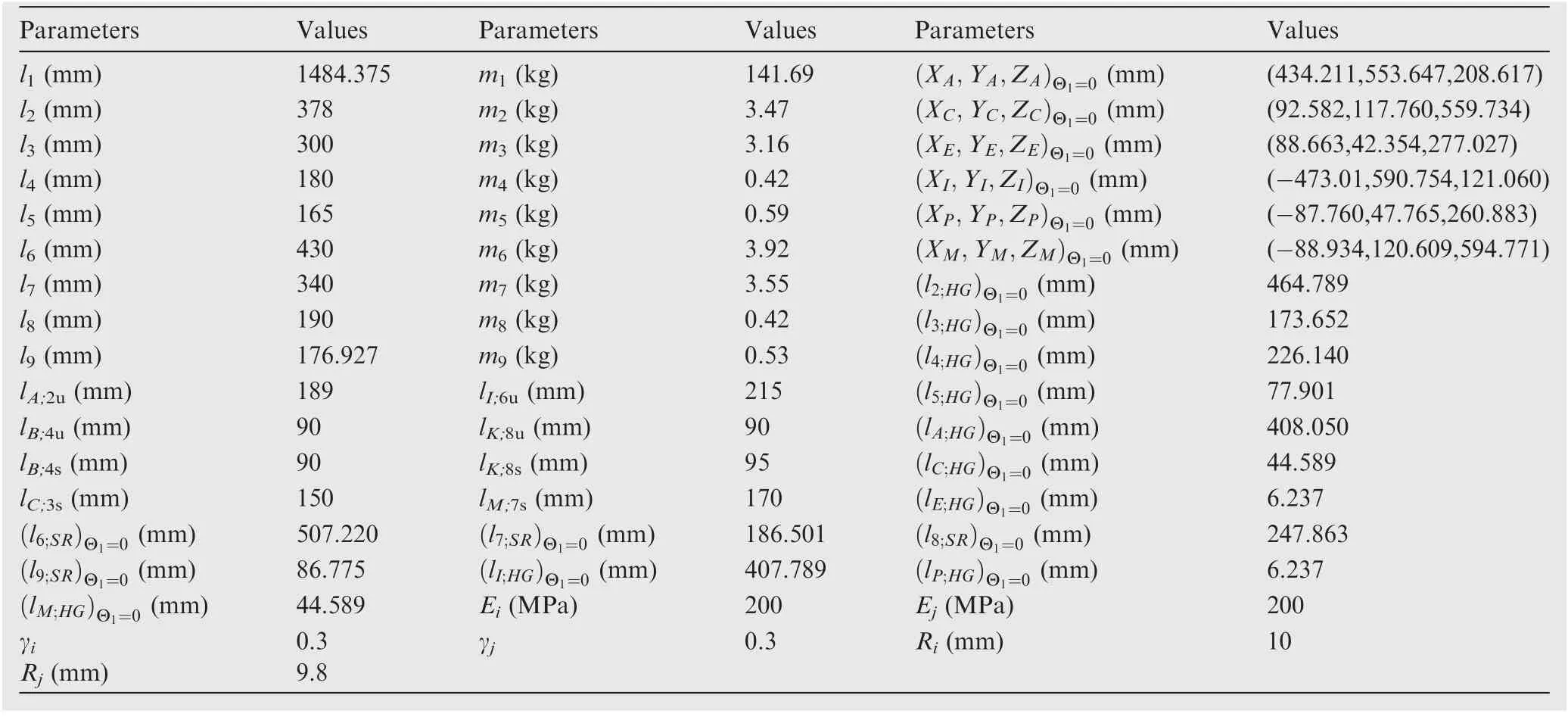
Appendix. A. Main parameters of the DSS landing gear
 Chinese Journal of Aeronautics2022年7期
- Chinese Journal of Aeronautics的其它文章
- An online data driven actor-critic-disturbance guidance law for missile-target interception with input constraints
- Study on excitation force characteristics in a coupled shaker-structure system considering structure modes coupling
- Smooth free-cycle dynamic soaring in unspecified shear wind via quadratic programming
- Active and passive compliant force control of ultrasonic surface rolling process on a curved surface
- High dynamic output feedback robust control of hydraulic flight motion simulator using a novel cascaded extended state observer
- Composite impact vector control based on Apollo descent guidance
