Trajectory optimisation in electrical discharge machining of three-dimensional curved and twisted channels
Jianshe ZHAO, Yiong QIU, Jian YUAN, Chao LIU
a College of Mechanical and Electrical Engineering, Nanjing University of Aeronautics and Astronautics, Nanjing 210016, China
b Laboratory of Integrated Electrical Processing, Nanjing HANGPU Machinery Technology Company Limited, Nanjing 210000, China
c Military Representative Bureau of the Air Force Equipment Department in Shanghai and Military Representative Office in Zhuzhou Region, Zhuzhou 412002, China
d AECC South Industry Company Limited, Zhuzhou 412002, China
KEYWORDS Blisk;Electrical discharge machining (EDM);Electrode;Objective functions;Trajectory generation
Abstract Numerical control electrical discharge machining(NC EDM)isone of the most widely used machining technologies for manufacturing a closed blisk flow path,particularly for three-dimensional(3D)curved and twisted flow channels.In this process,tool electrode design and machining trajectory planning are the key factors affecting machining accessibility and efficiency.Herein,to reduce the difficulty in designing the electrode and its motion path in the closed curved and twisted channels, a heuristic search hybrid optimisation strategy based on channel grids is adopted to realise the initial electrode trajectory design search and optimised size reduction.By transferring the trajectory optimisation constraints from the complex free-form surface to numbered grids,the search is found to be more orderly and accurate.The two trajectory indicators,namely argument angle and minimum distance,are analysed separately for the optimised results of the adaptive learning particle swarm optimisation algorithm, demonstrating that they can meet the actual processing requirements.Experimental results of NC EDM indicate that the motion path generated by this design method can meet the machining requirements of 3D curved and twisted flow channels.
1. Introduction
As blisk turbomachinery is typically used for the generation of energy and power,it plays an important role in the aerospace sector; for example, it is used to compress air and generate propulsive forces.A closed integral structural design is being increasingly used in such turbomachinery to reduce the working fluid loss due to combined blisk structures,which inevitably produce manufacturing errors. Lejon et al.studied the impact of manufacturing variations on the performance of an axial compressor rotor at design rotational speed. They found that manufacturing variations constituted the main reason for the change in rotor performance. As blisk turbomachinery is often operated in extremely harsh environments characterised by high temperatures and pressures(1100-2000°C, 20-25 atm), high-temperature resistant materials,such as nickel-based alloys,are often used. This increases the difficulty of machining, leading to higher manufacturing requirements.
Present manufacturing processes for closed blisks include multi-axis CNC milling, precision casting, welding, and electrochemical machining.However, these processes possess severe drawbacks that render them inadequate for manufacturing high-quality blisks. Conventional precision machining,such as milling,cannot be used because it is difficult to enter the channels between the strongly curved and twisted blades.Castingand weldingoften cannot meet the significantly high machining-accuracy and surface-quality requirements.Electrochemical machiningis problematic because of the existence of machining gaps; additionally, the flow field and electric field at the forming stage of the intake and exhaust edges are extremely complicated, resulting in size and shape errors in the formed edges.
In contrast, electrical discharge machining (EDM),possesses several desirable features, such as high forming accuracy, absence of macro-scale forces, and the capability of processing difficult-to-cut materials and complex surfaces.Compared with other machining technologies,EDM is advantageous for the fabrication of a closed blisk.However,electrode design and trajectory planning have always been challenging in the EDM of blisks,as a closed blisk generally contains narrow, curved, and twisted three-dimensional (3D)channels.
To overcome these limitations,Li et al.used non-uniform rational B-spline surface modelling to generate a 3D model of the blisk. They designed a complete set of tooling clamps according to the structural characteristics of the overall blisk,and found a way to perform the necessary measurements online. Their simulation of the machining process provides a reference for subsequent machining experiments.In investigating electrode-thickness reduction,Hou et al.used a reverse search algorithm to plan the trajectory of a bipolar shrouded blisk and optimised the electrode thickness, which was then verified using simulation software. Li et al.presented a ‘‘primary axis searching method” to determine the machining trajectory of a turbine disc. When the main motion axis faces interference,the other motion axes continue to search;a feasible trajectory can be obtained by repeating these steps.Following up on this study, Liu et al.proposed a heuristic search method based on tangent tracking; this method prioritised the search of trajectory points that closely coincided with the channel centreline and further improved the smoothness of the trajectory. Ayesta et al.proposed a trajectory design for algorithm search and optimisation based on the tangent tracking method. They selected a hybrid method combining a trust region and a genetic algorithm to search for the trajectory of the electrode movement of a leaf disc with a crown;the trajectory obtained was found to have excellent smoothness.For the EDM of a closed blisk, Kang et al.optimised the position and attitude of the electrode by calculating the maximum free distance of the electrode in the channel in a certain direction; they sparsely processed the numerical control (NC)code to obtain an electrode feed trajectory that could meet the machining requirements.
However, many research gaps still exist in the design of motion trajectories of EDM with closed curved and twisted channels, such as low search efficiency, conservative electrode size reduction, and difficulty in repetitive search optimisation in a specific small area. Most of these gaps involve optimisation problems.With the emergence of bionic intelligent optimisation algorithms,new research tools have been developed for the search and optimisation of electrode trajectories. One bionic intelligent optimisation algorithm,the particle swarm optimisation(PSO)algorithm,realises iterative optimisation in a given solution space by simulating the process of bird foraging.The traditional PSO algorithm easily falls into a local optimum;avoiding this requires continuous adaptive optimisation of the internal parameters. Wang et al.developed a hybrid PSO algorithm, adaptive learning particle swarm optimisation(ALPSO), that employs an adaptive learning strategy. Their experimental results on 40 benchmark test functions demonstrated that the convergence accuracy and convergence speed of ALPSO are significantly higher than those of other PSO algorithms.This highly portable research tool represents a significant advance in the study of trajectory optimisation problems.
In the present work, a 3D curved and twisted channel in a closed blisk is selected as the research object. After the height and thickness of the initial electrode are reduced, a hybrid heuristic search optimisation strategy based on channel grids is used for the first time to search for the electrode trajectory that optimises the electrode entity size. This method can address the problems of low search efficiency and highdensity search for a specific area. The implementation of the method to realise an accurate and efficient design of the electrode and its trajectory is also explored. This research would provide a valuable reference for the trajectory optimisation design of complex closed curved and twisted channels and the optimisation of electrode size reduction.
2. Analysis of research objects
The local schematic diagram of a closed blisk with 3D curved and twisted channels is shown in Fig. 1. The outer and inner ring radii of the hub are 92 mm and 133 mm, respectively; 32 blades having free-form surfaces are evenly distributed around the blisk axis, while the thinnest part dis 0.735 mm. The average width of the inter-blade channel is 21 mm, and the inlet and outlet cross-sectional areas vary significantly. The challenges faced during the EDM for such a curved and twisted channel are as follows:
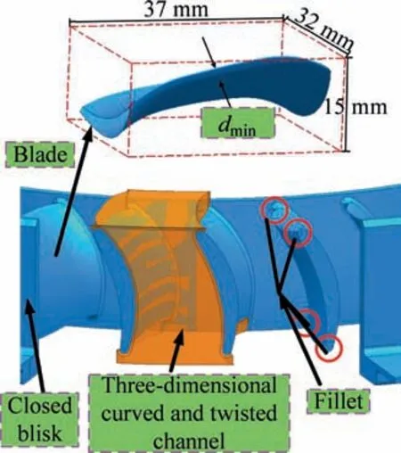
Fig. 1 Closed blisk with three-dimensional curved and twisted channels.
1.Since the closed 3D channel between two blades is curved and twisted and the electrode surface is free-form,the electrode design and trajectory planning are complicated.
2. Owing to electrode loss and a large number of channels among the blades,the process cycle of electrode manufacturing and measurement is relatively long.
3. It is difficult to clean the root in the excessive fillet area by inserting the cleaning electrode.
4. The electrode size and thickness significantly influence the machining quality and efficiency of the inter-blade channel.
3. Electrode design method
3.1. Comparative analysis of processing method
The shape and trajectory of electrodes designed by different processing methods vary.Currently,two methods are available for processing closed curved and twisted channels: multielectrode and single-electrode processing.
Multi-electrode processing is shown in Fig. 2 (a). In this method, the channel is divided into several processing areas according to the structural characteristics of the channel so that it can feed along a simple trajectory. Furthermore, to ensure that joint marks (machining marks at the junction of two curved surfaces processed by two different electrodes)are not produced during machining, overlapping areas are often designed between multiple electrodes, as shown in Fig. 2 (a). The designed overlapping area is 12 mm in width,accounting for almost 40%of the overall size of the electrode.Therefore, the forming electrodes should be designed separately for different processing areas, for which unified design and manufacturing standards should be adopted. The advantages of this method are the feasibility of electrode trajectory planning and improvement of the efficiency of electrode manufacturing. However, this method requires multiple electrodes to be replaced, and may lead to joint marks and increased manufacturing costs.
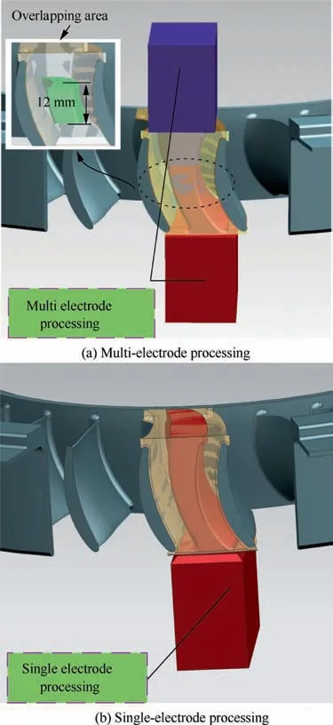
Fig. 2 Comparison of processing methods.
Single-electrode processing is shown in Fig. 2 (b), in which only one electrode is used to process the complete channel.The advantage of this method is that the channel surface is formed via a single clamp, and the processing consistency is good.However,for a complex curved and twisted channel,electrode trajectory planning is challenging, and high electrode loss occurs.
For a closed integral curved and twisted channel,the multielectrode processing method has been widely used as it avoids the complex electrode trajectory planning, decreases the difficulty of the design and manufacture of the formed electrode,and can machine many types of curved and twisted channels.In contrast, the single-electrode process is rarely used, mainly owing to its relatively complex trajectory planning, which often involves complex multi-axis linkage technology.
The above analysis shows that electrode trajectory planning can solve the problem wherein the single electrode cannot process closed curved and twisted channels; furthermore, it can optimise the number and shape design of multiple electrodes in sub-area machining. Since the trajectory planning method used in the single-electrode forming process is also applicable to the multi-electrode forming process, only electrode design and trajectory planning of the single-electrode processing method are investigated in this study.
3.2. Electrode profile design
The accuracy of the electrode profile is another crucial factor affecting the actual copy forming when the electrode moves to the final position. Because the forming electrode for the machining channel is usually obtained by reducing the height and thickness of the channel, the digital design accuracy of the channel affects the final actual machining accuracy. The channel is located between two adjacent blades; therefore,the digital design accuracy of the blade is equivalent to that of the channel. As shown in Fig. 3 (a), cubic B-spline interpolation is used for the value point of the original data on each blade section, and the blade surface is generated by the interpolation of the continuous smooth section line string. This generates the complete blade profile shown in Fig. 3 (b).Finally, a Boolean merging operation is performed on the hub, shroud, and blade group after the circumferential array to generate the closed blisk to satisfy all the requirements.
A copy forming type of EDM surface processing is adopted in this study,suggesting that the original shape of the electrode is consistent with that of the channel.To facilitate the processing of the electrode extending into the channel, the original electrode is typically designed by reducing the height and thickness before motion trajectory planning. Fig. 4 (a) shows the height reduction. Compared to the original shape of the electrode, the outer ring surface of the hub in the curved and twisted channel is offset by a certain distance (γ mm) along the radial direction of the blade disc, such that the electrode can move freely in that direction.Fig.4(b)shows the thickness reduction of the electrode. Compared to the original electrode shape, a certain angle β is offset to the blade basin face of the curved and twisted channel along the circumferential direction of the blade disc;thus,the electrode can move freely in the circumferential direction as well.
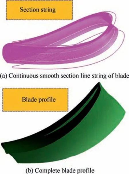
Fig. 3 Blade modelling process.
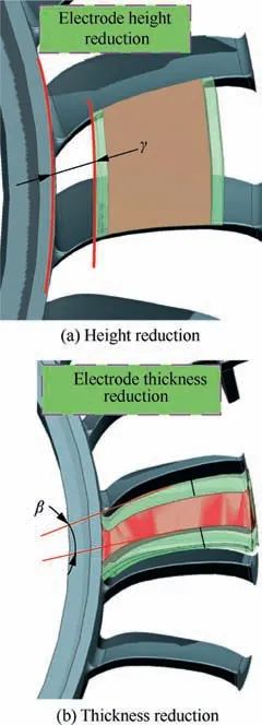
Fig. 4 Electrode height and thickness reduction.
However,reducing the height and thickness of the electrode is difficult.On the one hand,excessive reduction in size leads to insufficient rigidity of the electrode and a large deformation in the manufacturing process, making it difficult to ensure the accuracy of the electrode profile. On the other hand, an insufficient size reduction does not ensure the free movement of the electrode in the channel,making it impossible to further design the electrode trajectory.Therefore,the reduction percentage of the electrode height and thickness in the type of blisk shown in Fig.1 is generally approximately 50%-60%.The original rotation degree in the inter-blade channel was 10.2°, and only a space spanning a rotation degree of 4.97° was remaining after the electrode-thickness reduction. Therefore, the rotation degree of the reduced electrode was 5.23°after thickness reduction, accounting for 51.3% of the total channel space. However, for more complex curved and twisted channels, this percentage can be considerably higher; however, the electrode may lose its manufacturability and processing capacity.
4. Design of electrode trajectory
In Fig.5,the electrode motion trajectory includes the feed trajectory and generative machining trajectory. The feed trajectory corresponds to the movement of the electrode from the initial position of the workpieces to the forming position without interference, and the generative machining trajectory corresponds to the electrode finishing all profiles by electrode rotation from the initial position to the substitute position.In this study, the feed trajectory is investigated. In this paper,it is assumed that the electrode motion trajectory constitutes feed trajectory alone. As shown in Fig. 5, the generative machining trajectory(θ value)can be calculated and generated directly based on the feed result and final forming position.
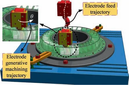
Fig. 5 Feed trajectory and generative machining trajectory of the electrode.
4.1. Channel gridding
To search the feed trajectory of the electrode in the curved and twisted channel accurately and in the correct order, an improvement is made in this study based on trajectory segmentation search. As shown in Fig. 6, after the pre-set machining clearance is offset to the entire channel, the segmented searching interval of the lth layer is divided into two dimensions,such that the curved and twisted channel can be gridded.Before generating the channel grids, as shown in Fig. 7 (a),the minimum package box should be placed as orthogonal to the datum axis as possible, which reduces the computational cost of reconstructing the constraint domain using spatial data points.As shown in Fig.7(b),by gridding the minimum package box and using Boolean intersection to retain only the grid inside the channel, the channel was meshed using the above steps. When the grids are sufficiently dense, the true shape of the channel can be realised.
Any area of the channel can be directly indexed by numbering the channel grids shown in Fig.7 and storing the data in a 3D array(m,n,l). By precisely calibrating the position of the electrode, the grids where the feasible pose is located can be searched based on a heuristic search method, and the trajectory planning problem can be transformed into a constrained optimisation problem.
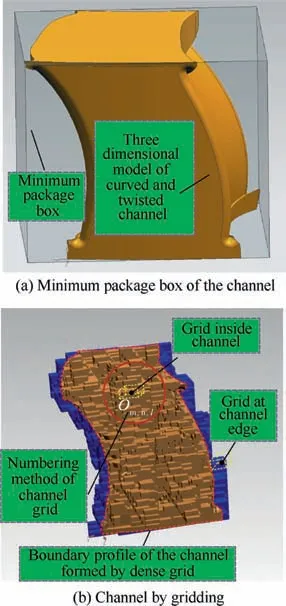
Fig. 7 Grid partition close to shape of curved and twisted channel.
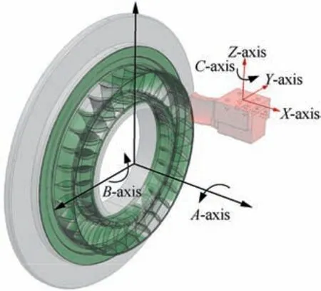
Fig. 8 Schematic of motion relationship between electrode and blisk.
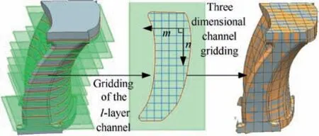
Fig. 6 Channel gridding process.
4.2. Relative motion relationship between the channel and electrode
Fig.8 shows that the motion track of the electrode for machining the 3D curved and twisted channel is a spatial curve.Therefore, the electrode has six degrees of freedom (DoFs)of motion: three translational DoFs (X, Y, Z) and three rotational DoFs (C, A, B).
Because the actual machine tool has only five axis linkages(X, Y, Z, C, A), the DoF of the B axis in Fig. 8 is not considered.Through homogeneous coordinate transformation in the Cartesian coordinate system, the transformation matrix of the three translational axes(X,Y,Z)is expressed as Eq.(1),which represents the magnitude of translation of the electrode relative to the X,Y,and Z axes after the electrode moves to a certain position. The transformation matrices of the C and A rotational axes are expressed by Eqs. (2) and (3), respectively.
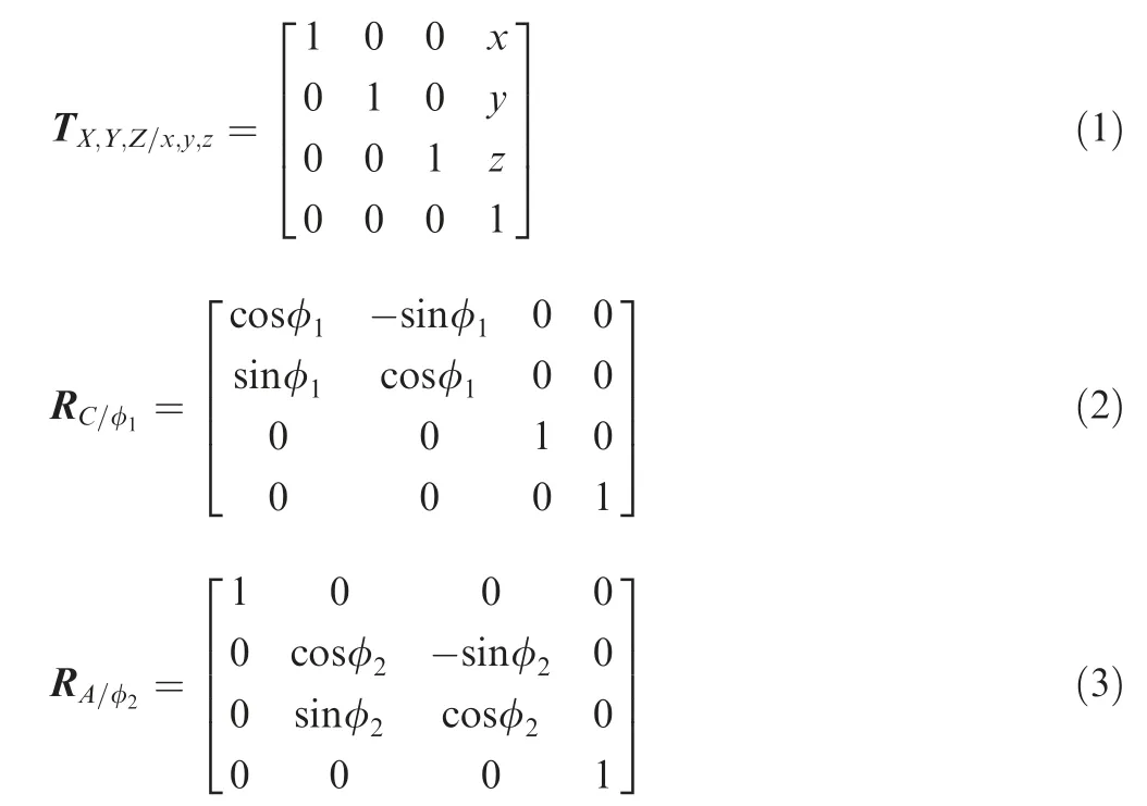
where φrepresents the magnitude of rotation of the electrode on the C axis relative to the previous position after electrode movement, and φrepresents the magnitude of rotation of the blisk on the A axis relative to the previous position.
4.3. Measurement of approximation degree of free-form surface
Since both the electrode and channel have free-form surfaces,the distance between each electrode surface and the outer edge surface of the channel changes continuously due to electrode movement. Traditional interference inspection only provides the determination result of the interference between the electrode and the channel boundary; however, it does not provide the specific approximation degree of each surface of the electrode and each surface of the channel at the interference-free position.Therefore,the traditional method to optimise the size of the electrode body based on interference checks is inconvenient. In an appropriate method, when the electrode moves in any position,real-time measurement of the maximum approximation degree of each electrode surface relative to the channel should be enabled, i.e. the approximation degree of free-form surface (ADFFS) δ.In practical applications, δ is often expressed as the reciprocal of the global minimum distanced, as shown in Eq. (4).
Fig. 9 shows that the global minimum distance dbetween the electrode surface section line pand channel surface section line qcan be obtained according to Eq. (5).
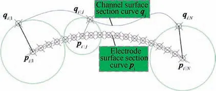
Fig. 9 Calculation of ADFFS.

4.4. Objective evaluation function and constraints
The objective evaluation function is important for trajectory search, and different evaluation functions result in different trajectory distribution intervals. The most widely used objective evaluation functionscan be expressed asfusing Eqs.(6)-(8).
Mean value type:
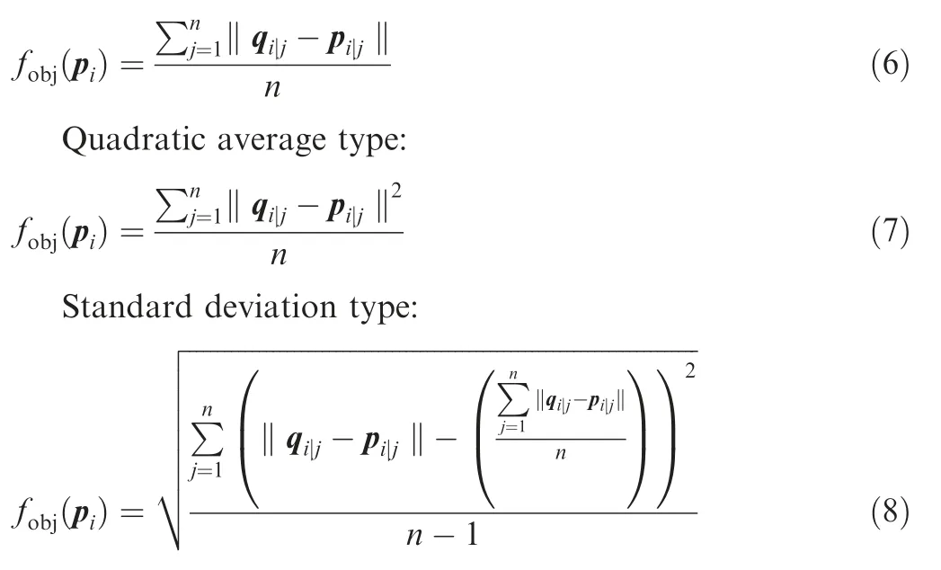
By comparing the single variable test results,the best channel grid interval given by the average and quadratic average types is biased on one side, which makes the electrode move far away from the central area of the channel.On the contrary,the results of the standard deviation type function are always partially located in the central area,which cannot continuously search for multi-layer channel grids. However, the two objective evaluation functions based on the principle of ADFFS,Eqs.(4)and(5),are suitable as evaluation functions of the trajectory because they retain the electrodes inside the channel while ensuring that they are as far away from the edges of the channel as possible.As a hyperbolic function,the gradient descent convergence speed of free-form surface δ is faster than that of a straight line,and it also has a higher search efficiency.Therefore,it is more suitable for calculating a large number of grids (Fig. 7).
The conventional trajectory search is constrained within the whole channel boundary,and the electrode movement is excessive, resulting in low search efficiency. However, the channel gridding reduces the constraint range to a single grid or multiple grids, thereby reducing the search area and increasing the search density and accuracy. As shown in Fig. 10, the minimum element constrained by the channel grid represents a cubic block. To simplify the constraint expression, it should be ensured that at least one edge of the grid is parallel to any coordinate axis, and the final expression is given by Eqs.(9) and (10).
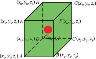
Fig. 10 Channel grid constraints.
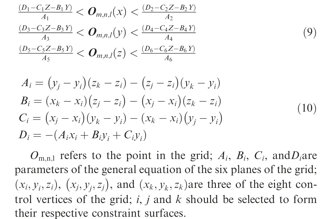
In Eq.(9),the X,Y,and Z components of the interior point of the grid are respectively limited to two planes;therefore,the value range of each component can be determined by the corresponding component value of the two planes. In Eq. (10),because the channel grid is determined by eight vertices, each face of the channel grid can have three corresponding vertices(three vertices determine a plane). Therefore, the four coefficients in the general formula of each plane can be determined by the coordinates of each component of the vertex. Through these constraints, the feasible region of the points inside each channel grid can be determined.
4.5. Heuristic search and hybrid optimisation strategy
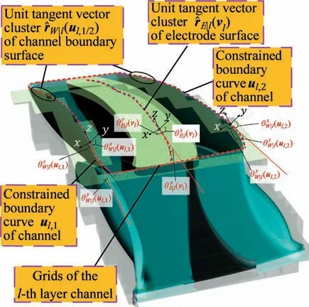
Fig. 11 Schematic diagram of heuristic search principle.
For electrode feed trajectory planning, search and optimisation are carried out on the channel grids. In the search stage,first, the grids having low approximation degrees of freeform surface close to the centre of the channel are selected.Then, based on the 3D tangent tracking methodshown in Fig. 11, heuristic search of grids is performed to capture the grids passing through the tangent plane of each boundary surface for each selected grid layer.
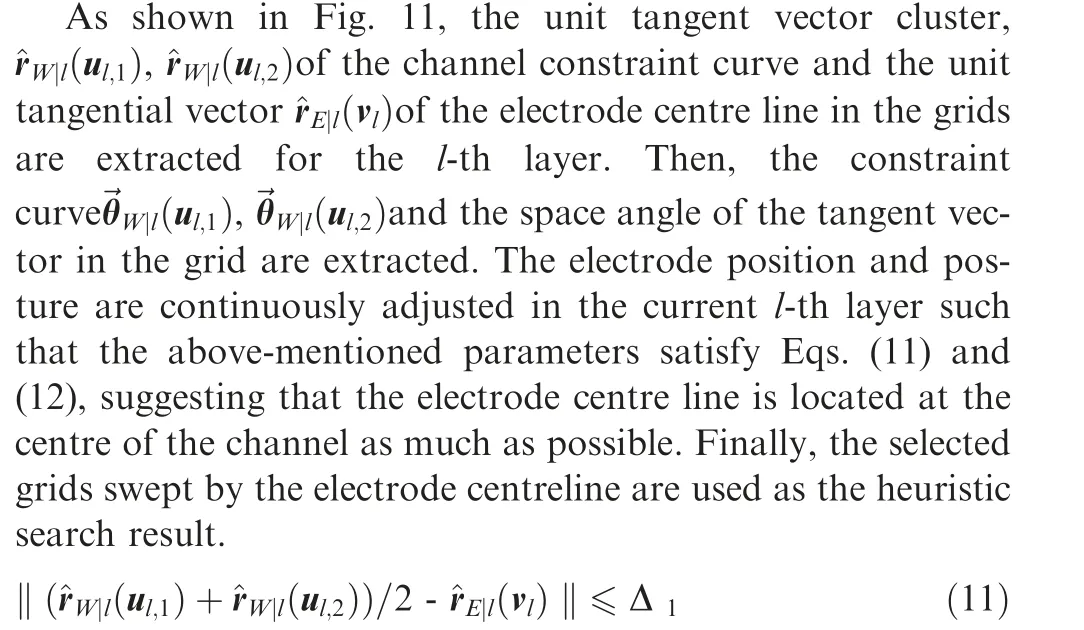
Δis the parameter related to the bending degree of the curved and twisted channel.

Δis the parameter related to the bending degree of the curved and twisted channel
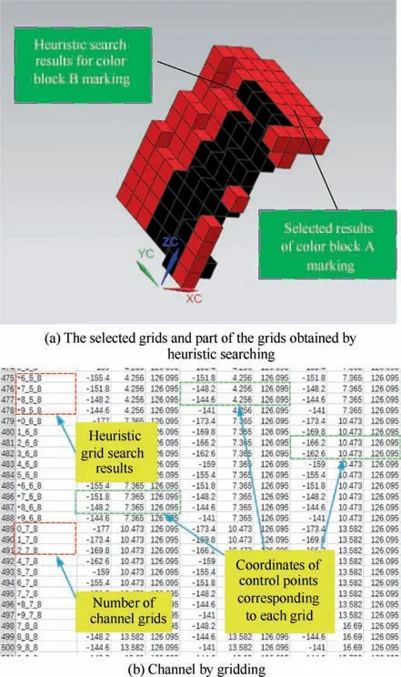
Fig. 12 Colour block number in search phase.
As shown in Fig. 12(a), colour blocks A and B are used to mark and number the selected grids and part of the grids obtained by heuristic searching. It is evident that the heuristic search further reduces the practical feasible region of the electrode trajectory. As shown in Fig. 12(b), all grids are numbered in the database, and the 3D coordinates of its eight control vertices are stored. The selected grid and heuristic search grid are distinguished from other grids using additional markers.
After the preliminary search for the channel grids meets the above-mentioned conditions, each grid is evaluated again using ADFFS. This enables high-quality grids to be screened in each layer and reduced to trajectory points. However, the grid size of the channel reaches the order of magnitude of the electrode discharge gap; therefore, the electrode trajectory needs to be further optimised under the general order of magnitude.
The optimisation of the electrode feed trajectory is essentially a nonlinear programming problem; however, its difficulty is significantly reduced as the constraints are simplified to grids. The optimisation can now be divided into position optimisation and attitude optimisation.
Since attitude optimisation is often not the main optimisation objective, it is used in the search process to validate the interference check. In hybrid optimisation, which is different from the above-mentioned method, the position and attitude are optimised simultaneously. The ALPSO algorithm is used to solve the global optimisation problem.In Fig.13,the traditional PSO algorithm considers the variables to be optimised(i.e. position and attitude of the electrode) as particles that have two attributes of velocity and position. Eqs. (13) and(14)show the velocity and position update formulas of the particles, respectively.

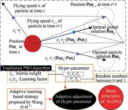
Fig. 13 Particle swarm optimisation algorithm based on adaptive learning strategy (ALPSO).31
Posis used to record the optimal global solution; Posis used to record the optimal particle solution; cis the inertia weight of the velocity of particles; cand care the learning factor of the global optimal solution and individual optimal solution, respectively; rand rare random numbers between 0 and 1.The above-mentioned parameters can guide the particles to move to the region where the optimal solution is most likely to exist.
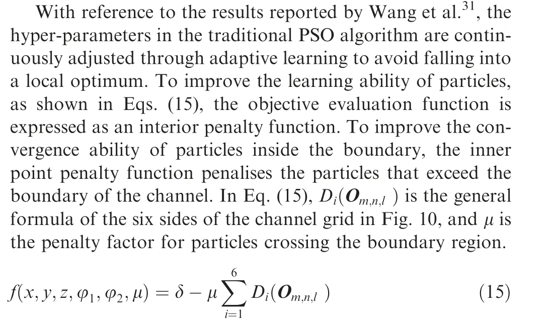
As shown in Fig. 14, in the same channel grid where the electrodes are located at the same initial position, the ALPSO algorithm with the traditional PSO algorithm was compared.Fig. 14(a) and (b) are similar in that the most dense particle aggregation is seen around the diagonal of the channel grid,indicating that there exists an optimal solution in the diagonal region that can make the particle swarm converge collectively.However,in the process of finding the optimal solution for the traditional particle swarm shown in Fig.14(a),a large number of particles attempt to cross the constrained domain of the channel grid, which consumes considerable computing power.Furthermore,in the adaptive learning particle swarm shown in Fig. 14(b), although particles are sporadically distributed around the constrained domain, most particles are only close to the optimal solution, and are constantly attempting to skip the local optimal and search for unsearched areas. The results show that ALPSO is more suitable for the optimisation of the position and attitude of the electrode based on the channel grid.
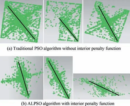
Fig. 14 Comparison of ALPSO algorithm and traditional PSO algorithm.
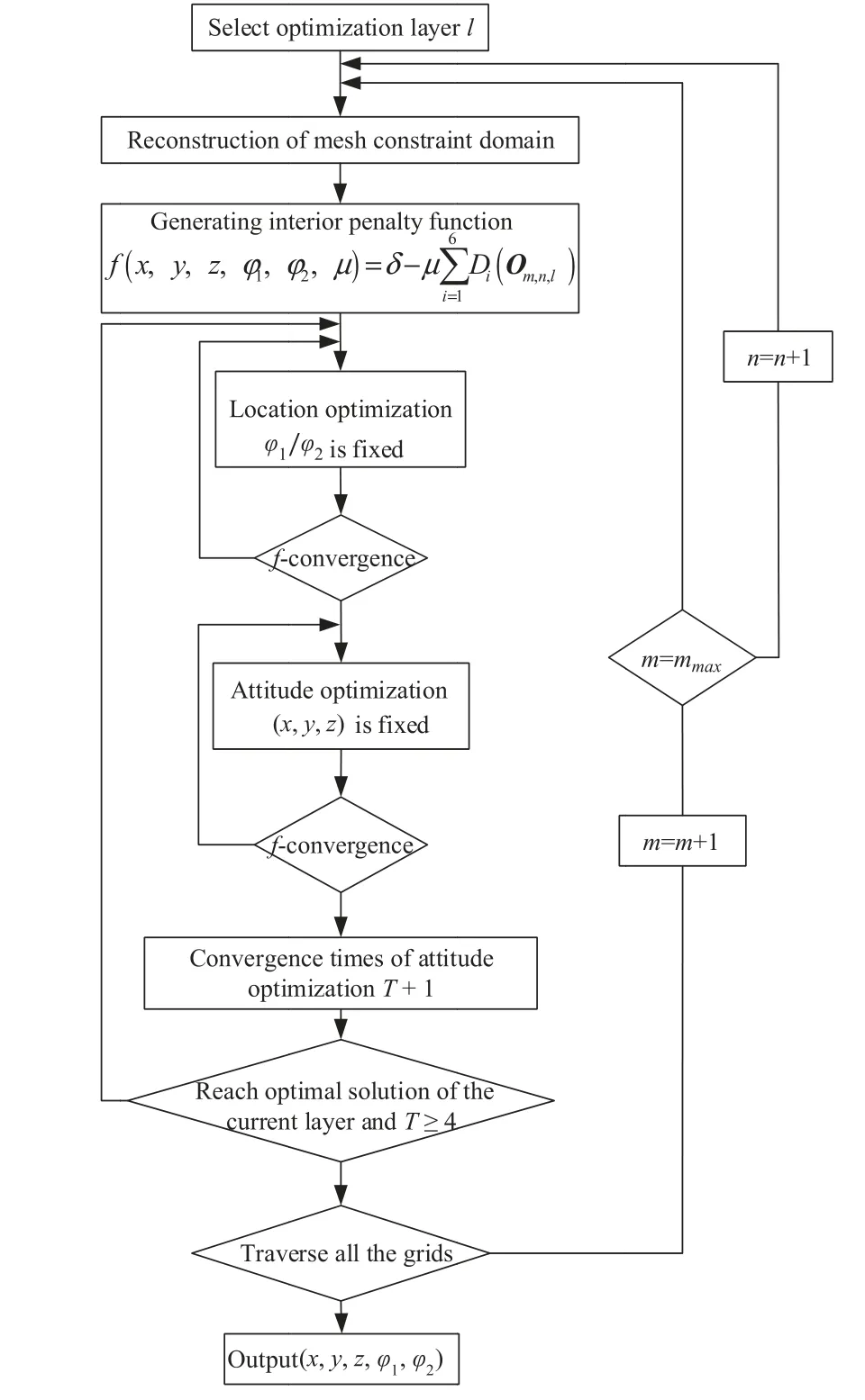
Fig. 15 Trajectory hybrid optimisation process based on ALPSO.
Based on the above-mentioned research, the final hybrid optimisation process is shown as Fig.15.The iterative solution of the objective evaluation function is realised by the nested loop of pose optimisation and traversing all grids to obtain the optimal solution of the current layer. To ensure that ALPSO has sufficient adaptive learning time in a single grid, the iteration period to three times was set,which implies that when T is greater than or equal to four, the loop ends.
To evaluate the heuristic search and hybrid optimisation strategy objectively, it was compared with the 3D-tangent tracking methodand traditional PSO in terms of the time and optimal solution (d). The three optimisation methods are all given the same position and attitude in the same channel layer. As shown in Fig. 16, the heuristic search and hybrid optimisation strategy requires the most time among the three because the other methods do not involve optimisation steps but the search operation alone. The results indicate that the heuristic search and hybrid optimisation strategy is the best;furthermore, the traditional PSO algorithm is the worst, and the 3D-tangent tracking method is slightly better. This is because the traditional PSO can easily fall into a local optimum and its results are full of randomness, whereas the fixed search mechanism of the 3D-tangent tracking method determines that the results cannot be continuously optimised. The above analysis shows that the proposed method has the advantages of continuous optimisation compared with the traditional trajectory design method, and it can avoid the phenomenon of local optimisation compared with the traditional optimisation method. Therefore, it can be applied to the optimisation of trajectory design in the closed curved and twisted channel.Moreover,the optimisation time required by the algorithm is relatively insignificant.
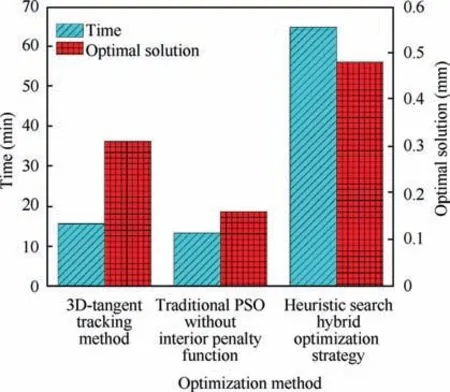
Fig. 16 Comparison of three optimisation methods.
4.6. Analysis of trajectory search optimisation results
By summarising the optimal solutions of each grid layer, the feed trajectory points are generated and spline fitting is performed. This is shown in Fig. 17, where the trajectory is seen to be located in the middle of the channel, and the ‘‘jump”degree is within the acceptable range. The average width of the channel is 12 mm, and the absolute value of the distance between the electrode and flow channel is less than 30% of the width.
The minimum distance dbetween the electrode and the channel is key to evaluating the results of channel meshing optimisation. As shown in Fig. 18, when the electrode enters the channel, the avoidance space between the electrode and channel is sufficient. After the electrode is completely inside the channel, the approximation degree gradually increases and starts fluctuating. When half of the channel is traversed,the approximation degree drops again.After reaching the layer where the processing position is located, the approximation degree reaches its maximum,which is only 0.28 mm away from the channel boundary.
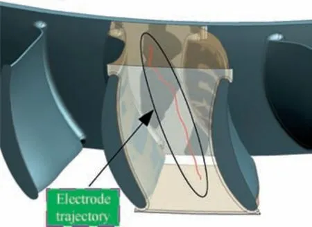
Fig. 17 Schematic of electrode feed trajectory.
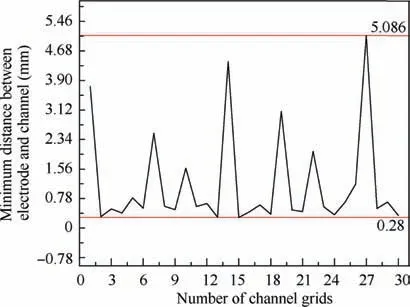
Fig.18 Trajectory index 1(minimum distance between electrode and channel).
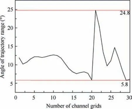
Fig. 19 Trajectory index 2 (attitude angle of electrode trajectory).
5. Processing test
Based on the trajectory shown in Fig. 17, the electrode size reduction is optimised,and the trajectory simulation and inter-ference check of the optimised electrode are also carried out.The machining experiment of the closed blisk is conducted on a five-axis EDM tool. A copper electrode is used, and the working fluid is kerosene. Table 1 shows the EDM specifications of the closed blisk.
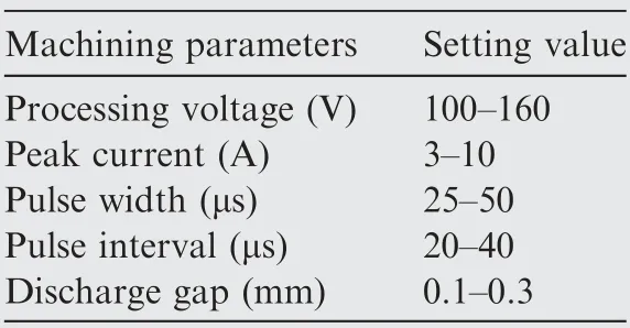
Table 1 Partial discharge specifications of EDM.
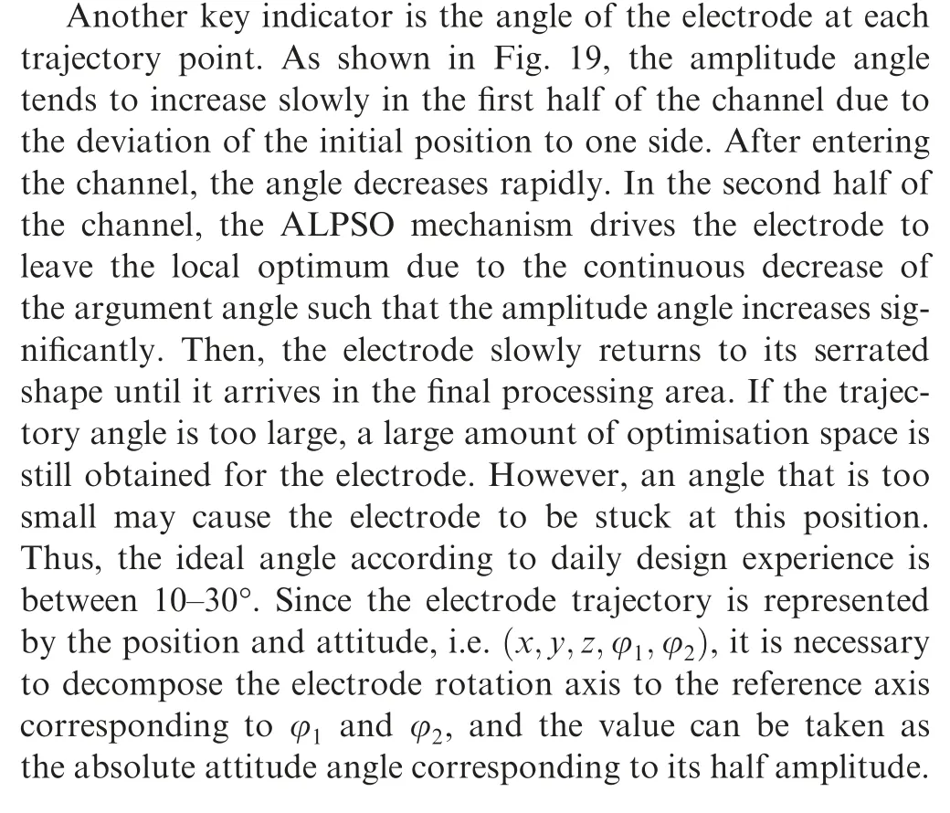
Before EDM,electrochemical machining technology is used to roughen the blank channel for opening the curved and twisted channel, which is conducive to the discharge of corrosion products in the subsequent electrode machining. In the EDM process,a stable electrode discharge,fine uniform spark,and absence of any carbon deposition are observed. After the forming process is completed, orbital machining and abrasive flow machining are used to polish the integral surface of the blade, and the overall processing time is 140 h. Fig. 20 shows the closed integral curved and twisted channel obtained by the orbital machining technology.
As shown in Figs.21,3D coordinate measurement was performed for the basin and back of the blade. In the measurement of the profile error, a 3D probe of diameter 2 mm was selected to measure the data points of the blade profile. The spatial coordinates of the measured points were compensated with 1-mm radius. Finally, the normal deviation between the measured results and the theoretical profile was calculated.In the measurement of torsion error, researchers maintained the probe position unchanged, considered the first blade measuring point as the base point,rotated the blisk after one blade was measured, and measured the offset of each blade measuring point relative to the first measuring point.
The blade profile error of±0.04,torsion error of±0.03°,and surface roughness of R≤1.6 μm were obtained. This experiment verifies the accuracy of the hybrid optimisation strategy based on channel grids and provides a solution to electrode trajectory planning of complex 3D curved and twisted channels.
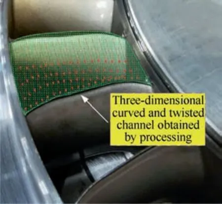
Fig.20 Machining results of closed curved and twisted channel.
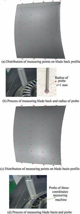
Fig. 21 Measurement of blade profile error.
6. Conclusion
In this study, initial electrode trajectory design search and optimised size reduction methods were explored for a closed blisk with 3D curved and twisted channels. Moreover, the results were verified experimentally. The main findings are as follows:
(1) The concept of channel gridding is proposed for the electrode feed trajectory planning of such a channel. By transferring the trajectory optimisation constraints from the complex free-form surface to numbered grids, the search is found to be more orderly and accurate.
(2) According to the heuristic search and hybrid optimisation strategy, the trajectory optimisation is divided into the mixed optimisation of position and attitude using the 3D-tangent tracking method and the ALPSO algorithm to heuristically search and optimise the selected grids. Finally, a reliable multi-axis electrode trajectory is obtained.
(3) Compared with the 3D-tangent tracking method and the traditional PSO algorithm, the heuristic search and hybrid optimisation strategy can better optimise the electrode feed trajectory. Therefore, the minimum distance between the electrode and the channel boundary is larger, and electrode interference during feeding is reduced.
(4) Based on the two key indicators obtained from the hybrid optimisation strategy of the trajectory heuristic search, an optimised size reduction of the electrode and an EDM test are performed. Results show that the proposed method is useful and that the processing efficiency of the single electrode is improved.Moreover,the method can be used for processing closed integral curved and twisted channels with other similar structures.
(5) The proposed method has some limitations that have not been addressed. The optimisation efficiency of the optimisation algorithm needs to be further improved,and the proposed method should be further combined with EDM orbital machining to improve the forming accuracy. This method will be further optimised in future studies to improve the efficiency of trajectory generation and better adapt to the specific process flow.
The authors declare that they have no known competing financial interests or personal relationships that could have appeared to influence the work reported in this paper.
s
This research was financially supported by Aeronautical Science Foundation of China(No.2011ZE52055)and Fundamental Research Funds for the Central Universities (No.3082018NF2018006).
 Chinese Journal of Aeronautics2022年4期
- Chinese Journal of Aeronautics的其它文章
- An automatic isotropic/anisotropic hybrid grid generation technique for viscous flow simulations based on an artificial neural network
- Optimization design of airfoils under atmospheric icing conditions for UAV
- Pressure distribution feature-oriented sampling for statistical analysis of supercritical airfoil aerodynamics
- Recent progress of machine learning in flow modeling and active flow control
- Design method of optimal control schedule for the adaptive cycle engine steady-state performance
- Using tandem blades to break loading limit of highly loaded axial compressors
