Design method of optimal control schedule for the adaptive cycle engine steady-state performance
Yiho XU, Hilong TANG, Min CHEN,*
a School of Energy and Power Engineering, Beihang University, Beijing 100083, China
b Research Institute of Aero-Engine, Beihang University, Beijing 102206, China
KEYWORDS Adaptive cycle engine;Control schedule design;Hybrid optimization method;Mode transition;Performance optimization
Abstract The alternative working modes and flexible working states are the outstanding features of an adaptive cycle engine,with a proper control schedule design being the only way to exploit the performance of such an engine. However, unreasonable design in the control schedule causes not only performance deterioration but also serious aerodynamic stability problems.Thus,in this work,a hybrid optimization method that automatically chooses the working modes and identifies the optimal and smooth control schedules is proposed, by combining the differential evolution algorithm and the Latin hypercube sampling method. The control schedule architecture does not only optimize the engine steady-state performance under different working modes but also solves the control-schedule discontinuity problem, especially during mode transition. The optimal control schedules are continuous and almost monotonic, and hence are strongly suitable for a control system,and are designed for two different working conditions,i.e.,supersonic and subsonic throttling,which proves that the proposed hybrid method applies to various working conditions. The evaluation demonstrates that the proposed control method optimizes the engine performance, the surge margin of the compression components, and the range of the thrust during throttling.
1. Introduction
The increasing complexity of flight missions drives the technological development of gas turbine engines. The conventional turbojet or turbofan engine cannot complete mixed types of missions, as these engines have specific properties determined by the engine structure. For instance, the turbojet engine is suitable for high Mach number flights but it has a poor fuel consumption in the subsonic conditions.Hence, such properties impose exploiting a turbojet only for simple flight missions. At beginning of the 21st century, American experts predicted that gas turbine engines have a large potential for aviation technology.So, research on this type of engine focused on improving the structure and ultimately developed the intercooled recuperated turbofan engine used in civil aviation,with the hydrogen-powered hypersonic precooled combined cycle engine used for hypersonic aircrafts.Among the various engine structures,the Adaptive Cycle Engine(ACE)is one of the most capable gas turbine engines that can adapt to flight mission changes.
The ACE has a similar working principle to the Variable Cycle Engine (VCE), with the latter possessing the potential of fulfilling both supersonic and subsonic flight missions.Indeed,the VCE is capable of altering many variable geometry components, such as rear variable area bypass injector, and variable area low-pressure turbine stator.Interestingly, some technologies used in the VCE can not only provide performance improvements but also reduce noise.Given that the ACE has more complicated components and uses more advanced technologies, it can be considered as the advanced VCE. The ACE was studied in the Versatile Affordable Advanced Turbine Engines program (VAATE),which focused on the schematic studies and technical identification of the adaptive cycle technology.
The ACE has been a hot research topic with several papers considering various aspects, such as the physical essence of matching relationships among the components,performance optimization,power extraction analysis,structure analysis,and performance uncertainty evaluation.Among these research directions, the control schedule attracts great research interest as it can explore the ACE’s performance potential.In the traditional turbofan engine,the control schedule is easy to be designed because there are only a few controlled variables. However, the control schedule design of the ACE is very complex due to the increased variable geometry components. The theoretical foundation of the control schedule design is to analyze the relationship between the variable geometry components and the engine performance. The authors analyze the effect of each variable geometry component on the engine’s performance and stability.The results reveal that there exist some universal rules that are appropriate for all the working modes, while the same paper provides insights for the control schedule design. The constant airflow throttling is also an important technology that benefits from the control schedule design. The core feature of the constant airflow throttling is that the rotating speed of the lowpressure shaft remains constant when throttling, which can decrease the spillage drag because it retains the inlet airflow of the engine. As the rotating speed of the low-pressure shaft remains constant, the throttling is conducted by adjusting other variable geometry components. Hence, the control schedules must be designed to complete the constant airflow throttling.The ACE has a strong capability in constant airflow throttling,and Lyu et al.designs the ACE control schedules for constant airflow throttling. Optimizing the engine’s performance is also an important research direction, as it can not only gain the optimal control schedules but also enhance the overall engine performance.Such an optimization scheme for the VCE at subsonic cruise conditions is managed through the ‘‘Reverse method” with the results highlighting that the installation performance is improved compared to the fixed-geometry alternatives.Yanginvestigates an ACE control schedule design considering the typical working conditions, i.e., highest-thrust, and lowest-fuel consumption.Zheng et al.proposes a novel concept to optimize the engine working line by improving its thermal efficiency. Besides the steady-state performance, the transient performance during the mode transition is also analyzed. The results indicate that by designing the control schedules during the mode transition,the latter can be safely conducted without violating surge and thrust constraints.Jia et al.analyzes the VCE control schedule design during the acceleration and deceleration of the engine with the results showing that the acceleration and deceleration time is reduced by optimizing the control schedule. The same work designs a new method entitled‘‘Transient-state Reverse Method”, which is a powerful method to design the acceleration and deceleration control schedule of the VCE.
According to current literature,the control schedule design of the VCE or ACE is very complex and involves the basic theory of variable geometry components, steady-state performance, and transient performance. The complexity is caused by the alternative working modes and the flexible control schedules. Throughout the literature related to control schedule design, it is highlighted that the steady-state performance is extremely important because it is the evaluation criterion of the engine performance. Evaluating the ACE’s steadystate performance can lay the foundation of the next research,such as installation performance, and fighter airframe/propulsion integration research.Therefore,in this paper,we focus on the control schedule design of the ACE’s steady-state performance. Despite some research towards this direction has already been done,this is still an open research case,as several problems still need to be solved.Firstly,choosing the working modes during throttling is still an unsolved problem, as the mode transition point is mostly heuristically chosen.However,an incorrect choice on the working modes may impose a performance deterioration, and therefore, further study on how to search for the optimal mode transition points is required.Secondly, optimizing the engine performance is crucial, as it is the key point to design the optimal control schedules.Despite optimization has gained much attention due to enhancing the engine’s performance, the practical aspect of the control schedules is neglected. This is important, as the optimized control schedule may be discontinuous increasing the complexity of the control system. This situation usually happens during mode transition, and therefore, searching the control schedules that are both optimal and smooth has a huge engineering value.
The problems expounded above can be summarized into two questions: how to choose the mode transition point to optimize the engine performance, and how to design the optimal and smooth control schedules.Solving these two questions can drive the research on the ACE from the theoretical studies to the engineering applications.To answer these two questions,we propose a hybrid optimization method that combines the Differential Evolution (DE) algorithm and the Latin hypercube sampling method. Our optimization model relies on the engine performance simulation model, which especially for the ACE, poses non-linear and strong-coupled characteristics.Therefore,traditional optimization methods that have a higher demand for the physical model(continuous, differentiable, etc.) are not suitable. Indeed, most of the optimization methods referring to gas turbine engines consider nontraditional approaches. For example, Liu et al.suggest a genetic algorithm, and Stornand Daset al. adopt a random search method named differential evolution.
During the initial optimization, it is possible to achieve the optimal engine performance for various working modes,which can confirm the mode transition point utilizing a performance comparison. However, the control schedules optimized by the DE algorithm cannot ensure continuity. So, in our work, the control schedules are re-optimized based on the Latin hypercube sampling method to generate continuous control schedules. By employing this dual-optimization strategy, we design the optimal control schedules, which can not only ensure the optimal engine performance but can also be applied to the engineering application, as the control schedules of the variable geometry components are continuous and monotonic.The mode transition process can be completed by only adjusting one component (Mode Switch Valve, MSV). Finally, we successfully apply our method to two important working conditions,i.e.,subsonic and supersonic flight,proving it has high universality.
The remainder of this paper is as follows.Section 2 presents the engine performance simulation model, while Section 3 introduces the optimization strategy for the adaptive cycle engine. Section 4 elaborates on the design of the working modes and optimal control schedules, and finally, Section 5 concludes this work.
2. Establishing engine performance simulation model
2.1. Structure of adaptive cycle engine
Fig. 1 presents the adaptive cycle engine with a rear variable fan, which is the configuration of the research object investigated in this paper. Different from traditional turbofan engines, there are two independent fans on the low-pressure shaft. The front one named ‘‘Front-fan” has a bypass named‘‘3rd bypass”, and does not have variable stator vanes. The second fan termed ‘‘Fan” has a bypass called ‘‘2nd bypass”,and has variable stator vanes to adjust the airflow, pressure ratio, and efficiency of the Fan. The core engine is also different from the traditional turbofan engines, as it incorporates a Core-Driven Fan Stage (CDFS) on the high-pressure shaft.The CDFS has a bypass called ‘‘1st bypass”, with the airflow from the 1st and 2nd bypass being mixed in the Forward Variable Area Bypass Injector (FVABI). Then the mixed airflow will be remixed with the mainstream air in the Rear Variable Area Bypass Injector (RVABI).
The main components of the ACE include the Front-fan,Fan, CDFS, High-Pressure Compressor (HPC), combustor,High-Pressure Turbine (HPT), Low-Pressure Turbine (LPT),FVABI,RVABI,afterburner,main nozzle,and the 3rd bypass nozzle. LPT drives the Front-fan and the Fan on the lowpressure shaft, and HPT drives CDFS and HPC on the highpressure shaft. This engine has three outer bypasses, with the 3rd bypass being behind the Front-fan,the 2nd bypass behind the Fan,and the 1st bypass behind the CDFS.The inlet of the 2nd bypass has a MSV, which conducts the mode transition.The engine has two working modes named the triple and the double bypass mode. The engine has in total eight variable geometry components, namely the Variable Stator Vanes(VSV) for VSV, VSV, VSV, the LPT variable area guider VAGand FVABI, the RVABI, the Main Nozzle Throat (MNT), and the MSV.
The ACE presented in Fig. 1 has two working modes that are mainly controlled by the MSV. The engine has a higher Overall Bypass Ratio (OBR) when the MSV turns on, which is suitable for the demand of low fuel consumption. Accordingly, the engine manages a lower OBR, when the MSV turns off, which is suitable for the demand of high thrust. A schematic of the ACE airflow in two operating modes is presented in Fig. 2. The definition of the outer bypass is:
(1) Split ratio of the 1st bypass

where Band Ware the split ratio and the airflow of the 1st bypass, respectively, and Wis the main mass airflow of the inner duct.
(2) Split ratio of the 2nd bypass

where Band Ware the split ratio and the mass airflow of the 2nd bypass, respectively.
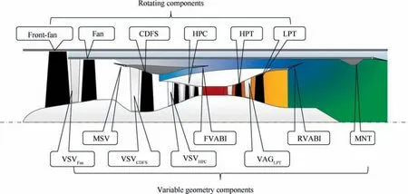
Fig. 1 Structure of adaptive cycle engine with a rear variable fan.
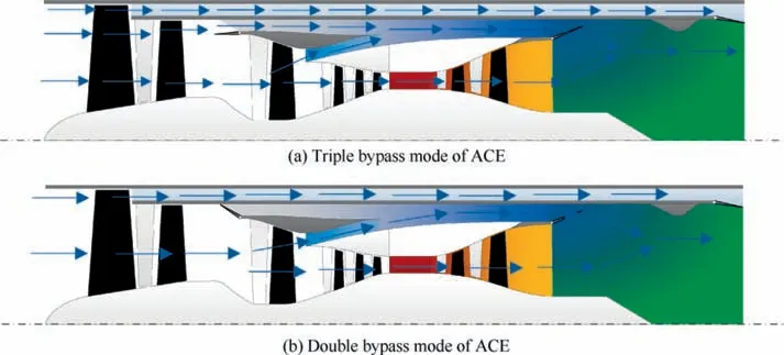
Fig. 2 ACE airflow in two operating modes.
(3) Split ratio of the 3rd bypass

where Band Ware the split ratio and the mass airflow of the 3rd bypass, respectively.
(4) The OBR of the engine is,

where B is the OBR.
2.2. Simulation description of adaptive cycle engine
This section introduces the ACE simulation model named engine performance simulation model, which is established to calculate both the design and the off-design points. The initial step involves confirming the engine’s design point, i.e., the standard operating condition of the engine, as the engine’s working conditions always vary. The engine design point is a very important stage of the component design level, as several component parameters,i.e.,mass flow rate,pressure ratio and efficiency,and geometry sizes must be confirmed.For the analysis that follows we employ the design parameters of Table 1,where TRD is the ratio of the maximum allowable turbine inlet temperature to the turbine inlet temperature in the design point.
Next,we analyze the interplay between the control schedule and the engine performance,with the control schedule param-eters mainly including the variable geometry components.Hence, the multiple angle characteristics describe the angular variations of the compression components,with Fig.3 presenting an example of the multiple angle characteristics of the rear variable fan, showing the relationships between the angle of the stator vanes and the corrected airflow or pressure ratio.As the angle of the stator vane increases, the pressure ratio and the corrected airflow also increase, and accordingly, the efficiency of the rear variable fan varies,as the angle of the stator vane varies. Indeed, the Front-fan, CDFS, and HPC all have their multiple angle characteristics.
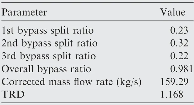
Table 1 Design parameters of ACE.
The correction factors, including the airflow and the efficiency correction factors, describe the angular variations of the LPT variable area guiders.When the variable area guiders turn on, both the airflow and the efficiency of the LPT increase, with an approximately linear relationship(R≥0.99, R is correlation coefficient) between the area and the airflow variations in the LPT (Fig. 4).
Additionally, we also define the area variations in the FVABI, RVABI, and MNT as:

where δAis the relative variation value, Ais the standard area, and Ais the actual area in one certain working point. The area variations of the VABI, including the FVABI and RVABI, are compared against the standard area calculated in the design point:
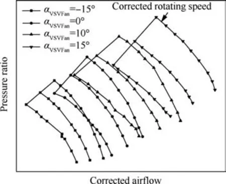
Fig. 3 Multiple variable-fan angle characteristic diagrams.
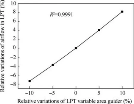
Fig. 4 Relative variations of mass flow vs LPT variable area guider.

where δAis the relative variation value, Ais the standard area, and Ais the actual area in one certain working point.The area variations of the nozzle throat have a similar expression with the VABI.
We also exploit the simulation model to calculate the engine’s off-design points and ultimately assist in solving the non-linear equations. The engine components are affected by mechanical, thermodynamic, and aerodynamic connections,which must obey principles such as power balance on the same shaft, airflow compatibility in the adjacent components, static pressure balance in the mixed stations, and rotating speed equivalence on the same shaft. The balance equations of the ACE can be established by using these principles. Given that the ACE has more components than a traditional turbofan engine, it involves eight balance equations. It is worth noting that the balance equations of the two modes are different.For further details regarding the balance equations,the reader is referred to Ref. 13. Overall, a common engine performance calculation model is 0-Dimensional, which is a mature model that uses the Newton-Raphson algorithm to solve the nonlinear equations.
3. Optimization strategy for adaptive cycle engine
The purpose of optimizing the control schedules is to exploit the performance potential of the engine.Traditional aero engines involve many variable geometry components, and thus it easy to establish an optimization strategy. However, the ACE involves more rotating components and variable geometry components,increasing the optimization variables and ultimately raising the optimization model complexity. Therefore,to design optimal and smooth control schedules,the optimization strategy must be further studied.
3.1. Confirming optimization variables
The purpose of optimization is to find the optimal control schedules of the ACE and establishing the relationship between the control schedules and the engine performance utilizing the engine performance simulation model. Given that the engine performance is mainly affected by the variable geometry components, during the optimization process we exploit the following parameters:

where α, α, and αare the angle of the Fan, CDFS, and HPC’s variable stator vane, respectively.δA,δA,and δAare the relative area of the LPT’s variable area guider,the RVABI,and the main nozzle,respectively,and Nis the relative rotating speed of the low-pressure shaft. The standard values of the area and rotating speed are ones defined from the design point.
3.2. Confirming optimization constraints
The optimization constraints are the boundary conditions,mainly including the optimization variables’ range and some constraints on the parameters that affect the stability and safety of the engine. Table 2 presents the value range of each variable geometry component.The range of α,αand αrefers to the angle of the stator vane, which differs depending on the compression component. Accordingly,δA, δAand δArefer to the range of the relative changing rate compared with the standard area calculated in the design point. Finally, Nis the relative rotating speed of the low-pressure shaft that has a different range depending on the cruise speed due to the total temperature difference at the engine inlet (N= 100% is the relative rotating speed of the design point).
In addition to defining the optimization variable ranges,we also consider the constraints affecting the engine’s stability.Hence, the high-pressure shaft speed Nshould not exceed 105% compared to its design point, and the HPC outlet temperature Tand the turbine inlet temperature Tshould not exceed their maximum allowable values (T, and T),respectively. Finally, the surge margins of the Front-fan,Fan, CDFS, and HPC should be larger than 15% to ensure adequate aerodynamic stability.
3.3. Confirming optimization targets
Different types of aero engines should have different mission demands, as generally, the civil aero-engine should possess a low Specific Fuel Consumption (SFC) to ensure an adequate flight range. Regarding military aero engines, their control schedule design is determined by the flight missions, and thus each mission (in broader terms) should have a different optimized operating schedule. For example, during cruising, the engine should ensure a low SFC while providing enough thrust. Accordingly, during high-power working conditions,e.g., maximum Mach number, take-off, spiral trajectory, etc.,the engine has to provide the largest thrust. Considering the high-power working conditions, the optimization target is given by:where F is the engine thrust, and Y = 10is the zoom factor.During the supersonic and the subsonic cruise, the engine should ensure the lowest SFC, while thrust should also satisfy the aircraft’s demand. Thus, the corresponding optimization target equation is:
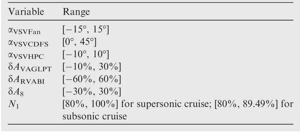
Table 2 Optimization variable ranges.


where Fis the target thrust, Wis the fuel consumption. Eq.(9) is a multi-objective optimization problem, and the typical solution is transforming it into a single-objective optimization problem that can be written as:

where Z is weight coefficient of the engine thrust.
However, in the single-objective problem equation, Z should be carefully chosen to prevent singularity. Therefore,Z is calculated exploiting a normalization method using the upper and lower bounds of the thrust and fuel consumption.As an example, considering T, the calculation steps to normalize the optimization target are:
Step 1. Confirming the optimization variables’ upper and lower bounds.
Both these bounds have been confirmed in Section 3.2,and from these, it is possible to calculate the bounds of the engine thrust and fuel consumption.
Step 2.Confirming the upper and lower bounds of the variables in the objective equation.
Eq.(10)includes two variables,the engine thrust F and the fuel consumption W.This step calculates the upper and lower bounds of the engine thrust and fuel consumption under the constraints of the optimization variables. The optimization model defining the upper bound is:

and the optimization calculating the lower bound is:

where I, I, I, I, I, I, and Iare the feasible ranges of the corresponding optimization variables shown in Table 2,EPCM is the engine performance calculation model, V is the vector of the optimization variables that are shown in Eq.(7), and SM represents the surge margin of the compression components.
Step 3. Normalizing the variables in the objective equation
This step is important to ensure the same weight range.The multi-objective optimization problem is transformed into the single-objective optimization problem by combining the variables in a single equation. The following equation refers to the optimization target that is not normalized and each function f(x) is a separated objective equation that has a relationship only with one of the target variables:

We use the upper and lower bounds of the objective equations to normalize every optimization target:
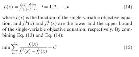
where C is a constant. Hence, the normalized single-objective equation can be written as:

Thus, ultimately the equation to optimize target Tis:

where Fand Fare the maximum and minimum thrust,Wand Ware the maximum and minimum fuel consumption,while α and β are the weight coefficient of the thrust and the fuel consumption, respectively. Given that as Fchanges the optimization targets vary, the complexity of optimizing the targets increases substantially. The weight of the thrust should be larger than that of the fuel consumption because ensuring enough thrust is the primary condition.Thus,it is possible to choose a larger than the normalized engine weight coefficient to reach the aimed thrust without affecting the optimization results. After calculations, we define Z = 2.5, as a universal value for the optimization target T.
3.4. Optimization method selection: A hybrid optimization method
Choosing the suitable optimization methods is crucial for completing the physical model optimization process. Literature affords several methods to solve such an optimization problem, and according to the optimal theory, the optimization process aims to find an extreme point at which the derivative value is zero.Given that the minimum point is one of the minimum values among all the extreme points,if the optimization function is convex, the extreme point is the minimum point.However, the engine performance simulation model is nonlinear and does not have explicit expressions, and therefore,high demanding methods,e.g.,convex,differentiable,etc.,cannot be used. Optimizing the engine performance simulation model is a non-smooth black-box optimization problem,which has a non-differentiable, discontinuous, and black-box objective function.Therefore,we solve this optimization problem utilizing the differential evolution algorithm,which is a random search method suitable for solving non-linear and multi-extremum models. It has a fast convergence speed and an excellent global optimal capability and has been successfully used in solving the optimization problem of the complex intercooled recuperated heat recovery system in the turbofan engine.However,the random search method can only ensure the optimum engine performance. The control schedules must be continuous and monotonic to meet the demand of the control system. In practice, the control schedules are not always continuous during throttling, which can increase the design complexity of the control schedules.This discontinuity appears at the mode transition point because the two working modes have different working states requiring different positions for the variable geometry components. Besides continuity, the variations of the control schedules should be monotonic to decrease the complexity of the control system.
Based on the continuity and monotonicity requirements,some variable geometry components that have already been optimized using the DE algorithm should be redesigned.However, if the optimal control schedules are changed, preserving the engine’s optimal performance cannot be granted. Therefore,the set theory can modify the control schedules,by introducing new control schedules entitled the optimal and smooth control schedules.The basic principle of searching the optimal and smooth control schedules exploiting the Pareto set is shown in Fig.5.The Pareto set is the set of the optimal control schedules that are continuous and monotonic.
The mapping relationship between the variable geometry components and the engine performance is:

where V is the set of the variable geometry components,and P is the set of the engine performance.

where Vand Pare the corresponding optimal sets of V and P, respectively, where the former optimal sets are essentially subsets of the latter utilizing the DE algorithm. Some sets within Vand Pare continuous and monotonic during throttling and the optimization seeks to find the suitable control schedules among the optimal ones. It should be noted that small deviations from the optimal engine performance are allowed, causing through variations on the variable geometry components defined as:

where ΔVis the deviation vector of the variable geometry components,and ΔPis the deviation vector of the engine performance. These new mapping relations expressed in Eq. (20)also belong to the set of the optimal solutions, and the modification in the optimal control schedules is to find the deviations that satisfy the demand of continuity and monotonicity.
To find the above deviations that still afford the control schedules to satisfy the control system demand, we exploit a sampling method named Latin Hypercube Sampling (LHS)that is based on probability statistics. This method is a stratified sampling method,which uses a part of the samples to represent the entire sample set. In this work, we employ this method to find the Pareto set from the set of the optimal control schedules, by following the steps:
Step 1. Generating the discretized samples of the singular points.
The preliminary optimal control schedules are defined using the DE algorithm.However,some of them in several operating points, named the singular points, are not continuous or monotonic.The variable geometry components presenting singular points can be identified using the control schedules figures, and Eqs. (21), (22):

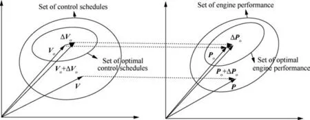
Fig. 5 Principle of searching Pareto set.
where vis one of the variable geometry components, the superscript R represents the rear working point, the superscript F represents the former working point, and ε is a very small value, superscript D represents the double bypass mode, superscript T represents the triple bypass mode.
This process stage generates samples of the singular points,where the discontinuous or non-monotonic variable geometry components should be discretized in the adjustable ranges.Thus, we use the Latin hypercube sampling to generate symmetrical samples,with Fig.6 presenting the sampling distribution of two sampling patterns between 0 and 1. In that figure,one pattern is generating the samples using the Latin hypercube sampling,while the other using the equiprobable distribution sampling. Opposing to the equiprobable distribution, the advantage of the Latin hypercube sampling method is ensuring a uniform distribution in the feasible region when the number of samples is small.Therefore,the Latin hypercube sampling is more suitable for generating the samples of the variable geometry components as it can use fewer samples and decrease the calculation time.
Step 2. Establishing the inference mechanisms
This step establishes the inference mechanisms to search for the generated samples obtained in Step 1 that are continuous and monotonic. The inference mechanisms include two types,the singular points that mainly affect the monotonicity of the control schedules, and the singular points located at the mode transition point, which should consider both continuity and monotonicity of the control schedules. The inference mechanisms are:
(1) Regarding the normal working points, the generated samples from the variable geometry components should satisfy Eq. (21).
(2) Considering the working points at the mode transition point,the generated samples from the variable geometry components should satisfy both Eq. (21) and Eq. (22).
By using the inference mechanisms, the variable geometry components in the singular working points can be modified to obtain smooth control schedules.
Step 3. Finding the Pareto set
The previous step identifies the set of the control schedules that satisfy the continuity and monotonicity requirements.However,to ensure an optimum solution,this step aims to find the Pareto set by filtering the set obtained in Step 2 and eliminating the parameters that do not satisfy the constraints.The latter ones are defined as:
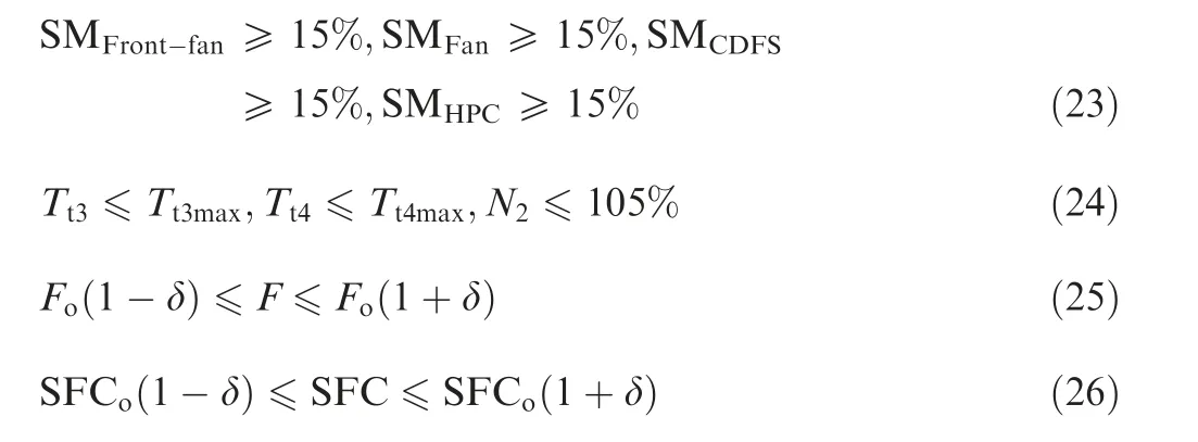
where Fis the optimal thrust gained using the DE algorithm,SFCis the optimal SFC gained by using the DE algorithm,and δ is the allowable value of the deviations. It is worth noting that the constraints on the surge margin of the compression components, temperature, and rotating speed are the same as the optimization constraints. Except from the optimization constraints, variations on the thrust and the SFC of the samples should be allowed in only a small range around the optimal solutions.
These three steps can find the Pareto set of the optimal and smooth control schedules during throttling. By combining the DE algorithm and the Latin hypercube sampling method, the optimal and smooth control schedules do not only satisfy the optimal engine performance but also satisfy the demand of the control system. Fig. 7 shows the optimization process diagram of the control schedules, which establishes the proposed optimization strategy by analyzing and optimizing the variables, constraints, targets, and the optimization method.
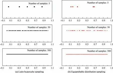
Fig. 6 Sampling distribution comparison between two sampling patterns.
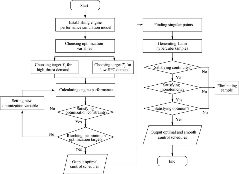
Fig. 7 Optimization process flow of proposed control schedules.
4. Design of working modes and optimal control schedules
Spurred by the appealing performance of the ACE in both supersonic and subsonic working conditions, in this work we focus on optimizing throttling at 11 km flight altitude for flight speeds of Mach number 1.5 for the supersonic cruise and Mach number 0.9 for the subsonic cruise. Given that during a flight the cruising stage is a very important working condition consuming the majority of the fuel,designing the control schedules for the cruise flight conditions is a major priority.
4.1. Optimal performance in supersonic and subsonic throttling
The ACE has two working modes, namely the triple and the double bypass mode. Utilizing the proper working mode during cruising is a very important problem affecting the engine performance. Therefore, we optimize the two working modes based on the engine performance simulation model.
Fig. 8 illustrates the optimal throttling lines of the two working modes during supersonic cruise. Relative thrust and relative SFC represent the relative variations compared with the corresponding maximum parameter values. The figure is divided into three regions that represent the suitable working modes. For 100% to 92.78% throttling, the double bypass mode provides higher thrust compared to the triple bypass mode, and thus the double bypass mode should be chosen.As the throttling increases,the engine performance in the triple bypass mode is better than that in the double bypass,inferring that the mode transition from the double bypass to the triple bypass mode must be timely completed to ensure a lower SFC. Indeed, the 92.78% to 81.59% throttling region, called the mode transition region, poses a minor difference between the two working modes and thus should be exploited to complete the mode transition.From 81.59%to 56.49%throttling,the triple bypass mode affords a higher engine performance and thus it should be chosen as the operating mode.In the latter throttling region, the maximum SFC decrease is approximately 6.26%.
Fig. 9 shows the corresponding optimal throttling lines for the subsonic cruise. Similarly, the figure is divided into three regions highlighting the suitable working modes and the results are similar to those for the supersonic cruise.Thus,the double bypass mode manages a greater performance from 100% to 91.56% throttling, the triple bypass from 84.24% to 51.84%throttling, and the mode transition region is defined from 91.56%to 84.24% throttling.Compared to the double bypass mode,the maximum SFC reduction on the triple bypass mode is about 5.34%.
Overall, the optimal engine performance during the supersonic and subsonic throttling is gained by optimization. Our results show that turning off the MSV can promote the maximum thrust leading to high maneuverability for the aircraft.On the other hand, turning on the MSV can decrease fuel consumption increasing fuel economy. In any case, transition between working modes must be conducted in the mode transition region to gain the optimal engine performance.
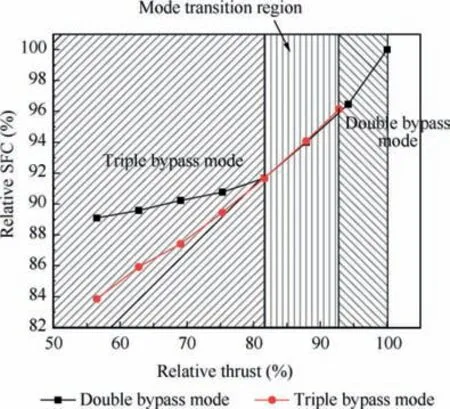
Fig. 8 Optimal performance of two working modes during supersonic throttling.
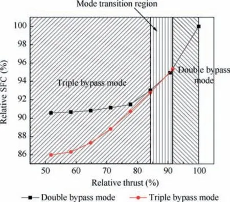
Fig. 9 Optimal performance of two working modes during subsonic throttling.
4.2. Design of optimal and smooth control schedules
We presented the optimal engine performance regions during the supersonic and subsonic throttling, and also the optimum mode transition region. However, great attention should also be paid to the design of the optimal control schedules.Opposing to optimizing the engine performance, optimizing the control schedules should additionally consider whether the optimum setup can be applied to the control system. Therefore, there is a large research interest in the mode transition as switching the working modes may cause large variations on the variable geometry components. To satisfy and simplify the design demand of the control system, we present the following mode transition rules to ensure a smooth transition process.
(1) The thrust should be close in the two working modes to decrease thrust fluctuation
(2) The variations of the variable geometry components should be as small as possible to decrease the complexity of the control system
(3) The airflow of the engine inlet should be the same.
4.2.1. Control schedule design in supersonic throttling
The optimal control schedules are identified using the DE algorithm. However, these are not smooth because their control schedules during throttling are not continuous and monotonic,and therefore,we employ the LHS to design the optimal control schedules. In this section, we show the design process for the supersonic and subsonic throttling.
Fig. 10 shows the optimal control schedules for supersonic throttling,with the mode transition point defining the working mode, i.e., double vs triple bypass, at 87.87% throttling compared to the maximum thrust.This is mainly due to the RVABI’s control schedules,as although adjusting the RVABI’s area has a little effect on the engine performance, it can affect the surge margin of the compression components. The variations of the RVABI’s area should remain similar with the optimal control schedules, which are 100% to 94.15% throttling in the double bypass mode and 92.78% to 87.87% throttling in the triple bypass mode. To ensure the continuity of the RVABI’s area, we set a throttling of 87.87% maximum thrust, as the mode transition point.
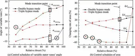
Fig. 10 Optimal control schedules in supersonic throttling.
Once the mode transition point is defined, the unsmooth control schedules can be found out. Fig. 10 highlights these points, with the control schedules in the rectangles needing to be adjusted to satisfy both the continuity and monotonicity,and the control schedules in the circle should be adjusted to satisfy the monotonicity.
The α, αand δAshould be adjusted to confirm the continuity and monotonicity of the control schedules. Therefore, we use the LHS method to generate the sets of the three variables. The monotonicity is confirmed by setting the minimum and maximum values of the optimization variables. Fig. 11 shows the optimal control schedules of the three variable-geometry components, with the relative thrust being the relative variation of the thrust compared with the optimal thrust in the mode transition point.The continuity is confirmed by searching for the lowest variations of the variable geometry components among the feasible sets shown in Fig.11.The variable geometry set affording an optimum transition between the two working modes is defined utilizing the Euler distance of the involved set points. If the distance in the mode transition point is small enough, these variable geometry component values are exploited to complete the mode transition.
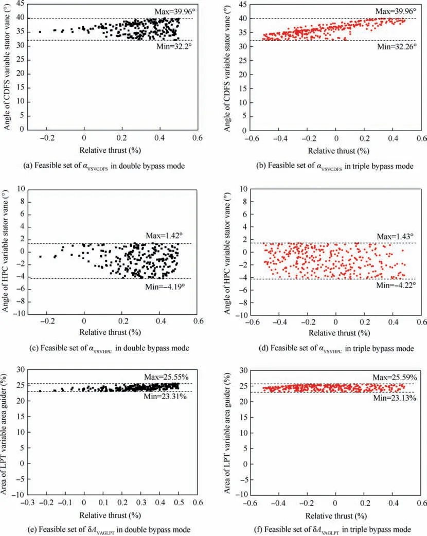
Fig. 11 Feasible sets of optimization variables.
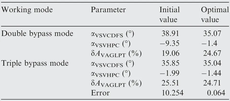
Table 3 Initial and optimal value of variable geometry components in mode transition point during supersonic throttling.
Table 3 shows the value of the variable geometry components at the mode transition point.The initial value represents the control schedules as provided by the DE algorithm, and the optimal value is after using the proposed hybrid method.It should be noted that before using the hybrid optimization method, there is a large Euler distance in the mode transition point, which means that a complex adjustment is necessary when changing the engine mode from the double bypass to triple bypass mode. However, the hybrid optimization method reduces the Euler distance in the mode transition point demonstrating that the control schedules are continuous. Additionally, the continuity of the control schedules at the mode transition point decreases the complexity of the control system.
Besides revising the control schedules at the mode transition point,we also utilize our method to analyze some working points that make the control schedules non-monotonic. As presented in Fig.10,the variations of the αand δAare not monotonic during throttling, and thus these working points should be modified to find the Pareto set. The feasible range of the Ais very small, as it has been determined by the variation tendency of the δA. Therefore, the δAshould be equal to - 60% to ensure monotonicity.The αat the 56.49% throttling should also be revised to ensure monotonicity.
After correcting the points that do not satisfy the demand,the control schedules of every variable geometry component are continuous and monotonic, with Fig. 12 showing the final control schedules in the supersonic throttling case. The thrust fluctuation between the two working modes is about 0.69%,which conforms to the continued demand of the thrust. Compared with the optimal SFC,the deviation of the SFC is about 0.34% in the double bypass mode and 0.09% in the triple bypass mode. The airflow of the engine inlet remains constant as the throttling is applied. The results presented in Fig. 12 show that the control schedules satisfy the requirements of optimality and monotonicity, and the mode transition process can be conducted successfully.In the mode transition point,all variable geometry components remain almost the same when transferring from the double bypass mode to triple bypass mode, which simplifies the design complexity of the control schedules.
Table 4 shows the changing range and direction of the final control schedules in the supersonic throttling case. The α, α, δAhas almost 100% variations and δAand δAabout 65% variations while throttling is applied.The changing rate of the αis smaller than the other variable geometry components.
The variations of every variable geometry component can be explained by using the working principles of the aeroengine presented in Fig. 13. The traditional turbofan engine must decrease the rotating speed to conduct the throttling.Regarding the ACE, the throttling can be altered only by adjusting the variable geometry components except N, which means that the engine inlet’s airflow and rotating speed of lowpressure shaft can remain constant.Increasing Aand decreasing Acan promote the expansion ratio of the LPT(π), thus causing the reduction of the turbine inlet temperature (T), with the latter decreasing both the thrust and the SFC,which are the main factors of performance.The α,α, and αdecrease as the throttling is applied,with variations in these variable geometry components increasing the OBR, which in turn decreases SFC.
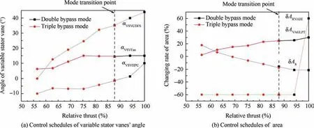
Fig. 12 Optimal and reasonable control schedules in supersonic throttling.

Table 4 Changing range and direction of control schedules in supersonic throttling.
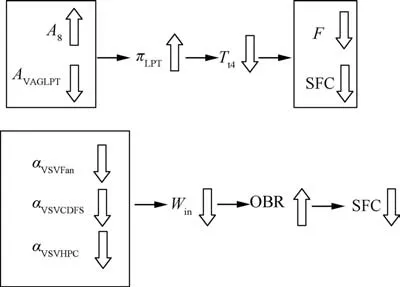
Fig. 13 Variation relationship between variable geometry components and engine performance.
Although adjusting the RVABI has a small effect on the engine performance,it does affect the surge margin of the compression components, especially at the working point of the maximum thrust. As shown in Fig. 14, the surge margin of the Fan will be less than 15% if the δAis less than 59.57%, and the surge margin of the CDFS will be less than 15% if the δAis less than 59.46%. To ensure enough surge margin for the Fan and CDFS, the δAshould be adjusted to 60%. On the other hand, the δAin other working points should be adjusted to - 60%. Therefore, the variations of the A(from 60% to - 60%) are necessary during throttling.
4.2.2. Control schedule design in subsonic throttling
We utilize the same design method for the subsonic throttling control schedules. For this case, the mode transition point is set at 84.24% throttling for the same reason presented in the supersonic throttling case. The optimal control schedules gained after optimization are illustrated in Fig. 15. However,some control schedules do not satisfy the demand of the control system. The mode transition point should consider four optimization variables, i.e., α, α, α, and δA(marked by the rectangles), which are not continuous and monotonic when the engine working mode changes from double bypass to triple bypass mode. Additionally, the control schedules marked by circles do not satisfy monotonicity.
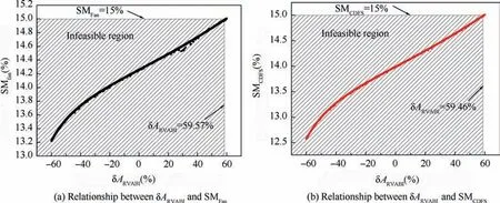
Fig. 14 Variations of SMFan and SMCDFS under various ARVABI values in supersonic working point of maximum thrust.
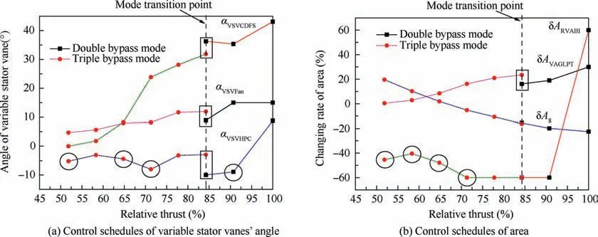
Fig. 15 Optimal control schedules in subsonic throttling.
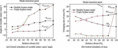
Fig. 16 Optimal and reasonable control schedules in subsonic throttling.

Table 5 Changing range and direction of control schedules in subsonic throttling.
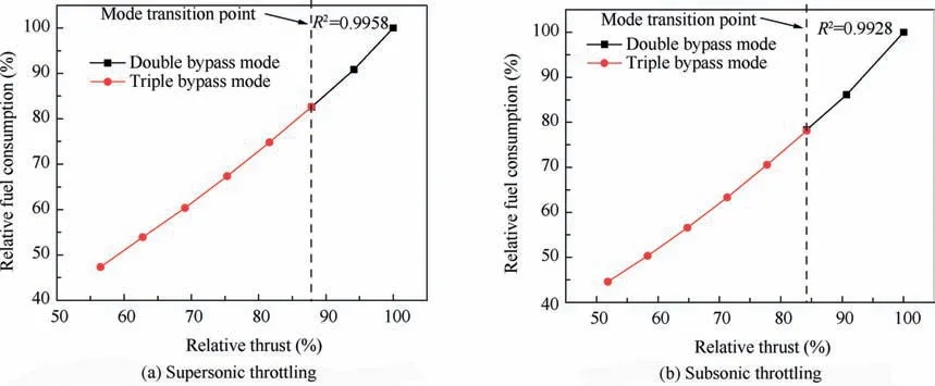
Fig. 17 Relationship between thrust and fuel consumption in supersonic and subsonic throttling.
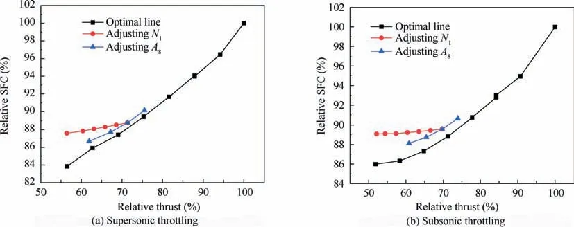
Fig. 18 Performance comparison among different control patterns in supersonic and subsonic throttling.
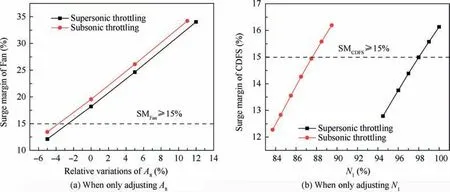
Fig. 19 Variations of surge margin when adjusting A8 or N1.
Fig. 16 shows the final control schedules in the subsonic throttling.During the mode transition process,the thrust fluctuation between the two working modes is about 1.17%, and the airflow of the engine inlet remains almost the same during throttling, proving that the mode transition is conducted successfully. Compared with the optimal SFC the deviation is about 0.70% in the double bypass mode and about 0.21% in the triple bypass mode. These results indicate that the control schedules in the mode transition point satisfy the demand of the continuity and optimality.As presented in Fig.16,all control schedules satisfy the demand of the continuity and monotonicity except from the δA. The variation tendency of the δAis not monotonicity,which is caused by the aerodynamic stability of the Front-fan. Thus, the δAshould be adjusted at -60% to ensure the monotonicity of the A, but in that case, for 64.80% to 51.84% throttling,the surge margin of the Front-fan would be less than 15%.However, the δAvariations are acceptable for the control system as these are relatively small for a throttling range of 64.80% to 51.84%. In the mode transition point, all the variable geometry components remain the same as the engine working mode changes from the double bypass to triple bypass mode. This is important as the design complexity of the control schedules is greatly simplified.
Table 5 shows the changing range and directions of the final control schedules for the subsonic throttling case. Interestingly,the changing directions of the variable geometry components are the same as for the supersonic case,with exception of the δA.The variations of the α,and αare smaller in the subsonic throttling, while the variations of the α, δA, and δAare larger.
4.2.3. Analysis on optimal control schedules
The control schedules involve in total seven variable geometry components, which vary as the thrust changes. Despite thrust is the main controlled variable,it cannot be directly controlled.Therefore, there should be an alternative controlled variable representing the thrust variations, with the fuel consumption being a very suitable option.As shown in Fig.17,there is a linear relation (R≥0.99) between the fuel consumption and thrust, in both supersonic and subsonic throttling. Therefore,the control system can establish the relationship between the fuel consumption and the variable geometry components to design the control schedules.
By using the hybrid method, we obtain the optimal and smooth control schedules in both the supersonic and subsonic throttling. Fig. 18 shows the benefit in engine performance by using the proposed hybrid method.We analyze the performance comparisons employing three control patterns, namely the optimal line using the control schedules shown in Fig.12 and Fig.16,the throttling line by adjusting only the N,and the throttling line by adjusting only the A. Considering the SFC reduction of the supersonic throttling case,the optimal line presents about 4.46%and 0.9% reduction compared with the throttling line that only adjusts Nor A,respectively.Meanwhile,the range of the thrust is extended in the optimal line(43.51%)compared with the other throttling lines (14.94% on adjusting Nand 13.64% on adjusting A), indicating that the potential of the engine performance has been fully exploited.
The analysis on the subsonic throttling manages the same results.The optimal line is reduced about 3.59% in SFC compared with the throttling line by only adjusting N, and about 1.64% compared with the throttling line that only adjusts A.The range of the thrust is extended in the optimal line(48.16%)compared with the other throttling lines(17.59%on adjusting Nand 13.09%on adjusting A).Although the engine performance by only adjusting Ahas a small difference with the optimal engine performance, it cannot complete the throttling because the surge margin of the Fan is not enough (SM-≤15%) for both the supersonic and subsonic throttling. As shown in Fig. 19(a), the surge margin of the Fan is less than 15% as the δAdecreases. Therefore, the changing range of the thrust is very small when we only adjust A, which does not ensure the demand of the engine thrust. Fig. 19(b) shows the relationship between the surge margin of the CDFS and N.Our results show that the surge margin of the CDFS is less than 15% as the Ndecreases, and if the surge margin is constrained rigorously,the range of the thrust will be smaller. So,only adjusting Ncannot complete the entire throttling process.
5. Conclusions
In this paper,we consider the adaptive cycle engine with a rear variable fan, and analyze its working modes and states in the supersonic and subsonic throttling. We design a hybrid optimization method to manage the optimal and smooth control schedules. From our research we conclude the following:
(1) The mode transition can afford a huge performance enhancement in both the supersonic and subsonic throttling. Utilizing a mode transition increases the thrust range about 7.22% in the supersonic throttling and 8.44% in the subsonic cruise, which benefits from the double bypass mode. Accordingly, the triple bypass mode has a lower specific fuel consumption than the double bypass mode, and our hybrid method manages a decrease in the specific fuel consumption of about 6.26%in the supersonic throttling and 5.34%in the subsonic throttling.
(2) The mode transition point should be confirmed by comparing the engine performance between the two working modes.In the mode transition point,the positions of the variable geometry components in the double bypass and triple bypass mode have very small deviations, meaning that the mode transition can be completed by adjusting only the mode switch valve.
(3) The variations of the δAincrease during the supersonic and subsonic throttling,while the variations of the other variable geometry components (α, α,α, δA) decrease. The variations of the δAhave a large effect on the surge margin of the compression components, and thus the δAshould be adjusted to 60% to preserve a large enough surge margin (SM ≥15%) for the Fan and CDFS on the maximum-thrust working conditions. The fuel consumption can be considered as the main controlled variable to control the variable geometry components as it has a linear relationship with the engine thrust.
(4) The performance and stability comparison among the three adjustment patterns prove that the design of the control schedules not only enhances performance but also improves the surge margin of the compression components.If we only adjust A,or N,the surge margin of the Fan and the CDFS, respectively, cannot be ensured in the safe threshold, and the constraints of the surge margin would cause the decrease in the range of the thrust.
The successful application in both supersonic and subsonic throttling has proved that this hybrid method is efficient and universal. The control schedules designed by this method not only manage the optimal engine performance but also are easily applicable to the control system.
The authors declare that they have no known competing financial interests or personal relationships that could have appeared to influence the work reported in this paper.
s
This research is funded by National Nature Science Foundation of China(Nos.51776010 and 91860205).And the research is also supported by the Academic Excellence Foundation of BUAA for PhD Students, China. The authors are thankful for the support from Collaborative Innovation Center of Advanced Aero-Engine, Beijing, China. And the authors would like to express their gratitude to EditSprings (https://www.editsprings.com/) for the expert linguistic services provided.
