Using tandem blades to break loading limit of highly loaded axial compressors
Bojie LIU, Chunhi ZHANG, Gungfeng AN, Du FU, Xinjun YU,*
a Research Institute of Aero-Engine, Beihang University, Beijing 100083, China
b School of Energy and Power Engineering, Beihang University, Beijing 100083, China
c Gree Electric Appliances, Inc. of Zhuhai, Zhuhai 519070, China
KEYWORDS Cascades;Highly loaded axial compressors;Loading limit;Single blades;Tandem blades
Abstract It is confirmed that tandem-blade configurations have potential to enlarge the flow turning in two-dimension (2D) studies. However, the potential of tandem blades to enlarge the design space for highly loaded axial compressors was rarely investigated in open literatures. The present work aims to show the capability of tandem blades to break the loading limit of conventional blades for highly loaded compressors. The 2D models of the maximum static pressure rise derived in previous work were validated by a large amount experimental data,which showed a good agreement. An E parameter was defined to evaluate the stall margin of compressor based on the theoretical models, which indicated that the tandem blade was able to increase the loading limit of axial compressors. A single-blade stage with a loading coefficient of 0.46 (based on the blade tip rotating speed) was designed as the baseline case under the guidance of the E parameter. A tandem-blade stage was then designed by ensuring that the velocity triangles were similar to the single-blade stage. The performances of both stages were investigated experimentally. The results showed that the maximum efficiency of the tandem-blade stage was 92.8%,1%higher than the single;the stall margin increased from 16.9%to 22.3%.Besides,the maximum pressure rise of tandem rotors was beyond the loading limit of 2D single-blade cascades, which confirmed the potential of tandem blades to break the loading limit of axial compressors.
1. Introduction
Lighter weight and higher efficiency have continuously been main aims of modern compressor design. One way to achieve the goals is to increase the stage loading coefficient. Higher loading level means to do more work and larger flow-turning angle for the individual rotor, which may lead to the insufficient stall margin. The stall margin could be evaluated by the maximum pressure rise potential (loading limit) proposed by Koch,which is widely used in compressor preliminary design procedure. It was generally recognized that the main limitation on pressure rise is flow separation of blade suction surface and endwalls. Tandem-blade configurations, with two split blades as shown in Fig.1,have potential to achieve higher loading and increase the maximum pressure rise without large flow separation by forming a new boundary layer on the Rear Blade (RB).
There has been a large amount of numerical and experimental investigations on 2D tandem cascades, showing the lower-loss advantages of the tandem-blade configuration at large flow turning angles. Saha and Roycompared the lowspeed single-blade cascades and tandem-blade cascades experimentally. The results indicated that the tandem cascade had wider range of angle of attack with acceptable loss. Hoegerand Mu¨lleret al. presented the numerical and experimental investigations of supercritical and subcritical tandem cascades in comparison with conventional cascades.The results showed that the tandem blade was superior in loss and turning at high speed, while the superiority of loss disappeared at low speed.Schneider and Kozˇulovic´confirmed the ability of the tandem configuration to extend the operating range and shortcoming at large negative incidence. In cascade studies, the wellknown Diffusion Factor (DF) defined by Lieblein et al.was generally regarded as a quantitative measure of aerodynamic loading limits, which mainly concentrated on the diffusion of suction surface. McGlumphy et al.demonstrated that there was a 20% drop in loss for the tandem cascades at the diffusion factor of 0.62.Hertel et al.investigated the aerodynamic limit of subsonic compressor tandem cascades numerically and experimentally.It was confirmed that that tandem blades were only beneficial at very large loading, for example DF >0.62.
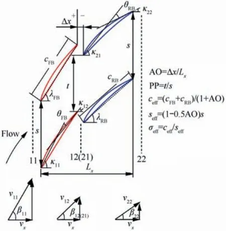
Fig.1 Aerodynamic and geometric parameters of tandem blade.
For the three-dimension (3D) compressor environment,several investigations were conducted to compare the tandem blades with conventional single blades. Brent and Clemmonsstudied the performance of a highly loaded single-blade rotor and two tandem-blade rotors with the design target of loading coefficient of 0.50.The results showed that only the 50/50 split tandem rotor achieved the designed loading coefficient and the target efficiency. Both tandem rotors had a stall margin of 17%, which were approximately the same as the single-blade rotor. Bammert et al.conducted an experiment of a four-stage compressor with two single-blade rotors and three tandem-blade rotors. The optimized tandem-blade stage reduced the loss of 18% with insufficient stall margin. Hasegawa et al.tested a transonic tandem-blade stage.The experimental results indicated that the stages had a work coefficient of 0.51 and a polytropic efficiency of 79.4%, while the stall margin was 10%. McGlumphy et al.numerically compared a tandem rotor in the rear stages of a core compressor with a geometrically similar single-blade rotor. The study showed that the tandem rotor attained a higher work coefficient,polytropic efficiency and numerical stall margin. Eshraghi et al.numerically compared a ultra-highly loaded transonic ultrahighly loaded single-blade stage and a geometrically similar tandem-blade stage. The results indicated that tandem stage mass flow rate and pressure ratio is respectively 48% and 9.3% more than conventional stage, but 3% decrease in isentropic efficiency. Tesch et al.conducted an experimental investigation of a tandem stator flow characteristic in a single stage low-speed compressor, which presented that with the incidence increasing, the loss in the tip region decreased whereas the hub region reveals higher losses in terms of size and quantity.The oil flow pictures showed that the separation zones at the rear blade is reduced at higher loading condition,which is different from single stators. Mohsen et al.undertook a numerical investigation of evaluating the potential of tandem rotors in improving the performance of transonic compressors. The numerical results revealed the tandem rotor had a 17% increase in the total pressure ratio and 2% increase in the rotor adiabatic efficiency, while the stall margin is lower than especially in off-design speed compared to the baseline rotor ‘‘NASA Rotor 37”. Wangand Yueet al. proposed a design and optimization strategy for the tandem arranged cascade and applied it on the stator of Stage 35. Results showed that the tandem configuration is able to significantly decay the separation and thus improve the overall performance in terms of pressure rise and efficiency. Kumar and Pradeepnumerically investigated the performance of a tandem stage compared with a conventional stage.The tandem stage had a higher total pressure rise and efficiency at design point, while the conventional stage behaved better at offdesign point.Other researchersalso investigated the application of tandem rotors and stators for subsonic and transonic compressor environment.
Most of researches have confirmed the efficiency advantages of tandem blades applied in highly loaded compressors.However,due to the lack of systematic comparison and experimental verification, it is still uncertain whether a compressor with tandem blades could increase the stall margin and even break the loading limit of conventional blades while maintaining an acceptable design efficiency.
In the present work, a conventional ultra-highly loaded compressor stage (with the loading coefficient of 0.46 based on rotor tip rotating speed)and a completely comparable compressor with tandem-blade design, which have equivalent preliminary design parameters with the conventional one, were designed and carefully tested in a large-scale low-speed axial compressor test facility. By comparing the performance characteristics of the two compressors, the loading limit of the two compressors could be determined. Moreover, based on the comparison of the measured inter-blade flow fields,the factors which could restrain the further increasing of loading level of the two compressors were discussed. Based on the present work, it hopes to provide some experimental supports for the future application of tandem-blade compressors.
2. Method for evaluating compressor margin
In order to show the potential of tandem blades to break the loading limit of highly loaded conventional compressors, it is necessary to use reasonable parameters to evaluate the compressor margin. As mentioned in above section, Kochcorrelated the maximum pressure rise (C) and geometry parameters (L is the diffusion length and gis the staggered spacing) to evaluate the compressor stall resistance capability,which was widely used in open literatures. The correlation is shown by a dotted line in Fig. 2. This criterion, C, is applied to a single-row blade in this paper as a measure of the loading limit, and an ideal E parameter is defined to evaluate the margin of the pressure rise.
In previous works, the theoretical models of the maximum static pressure rise for subsonic single-blade and tandem-blade cascades were derived using the similar analogical method of Koch,as shown in Fig. 2 by solid line and dashed line, respectively. And the models had been validated by a large amount of numerical cascade results. In this paper,experimental results of several single-blade cascades from open literatures are compared with the analogy model,which are the maximum static pressure rise of the tested cascades,which are plotted in Fig.2.These data represent the maximum loading capacity of controlled diffusion airfoil since the 1980s. It can be seen that most of the experimental results follow rather closely the trend of the limit of single-blade cascades, indicating that the model is suitable for determining the maximum pressure rise.
The comparison between Koch’s correlation and singleblade limit models indicates a significant disparity between the Cof cascades and stages. Several experimental data of different rotors at near stall conditions are plotted in Fig. 2,and main parameters of test cases are shown in Table 1.The experimental data are measured in subsonic compressor and represent the design method without extra flow control methods since the 1980 s. All the experimental data are adjusted to a representative Reynolds number and the ratio of tip clearance (ε)and staggered spacing (g), using the correlation given graphically by Koch.Here, the fitted functions for Reynolds number and ε/g, as shown in Eq. (1) and Eq.(2) are applied.
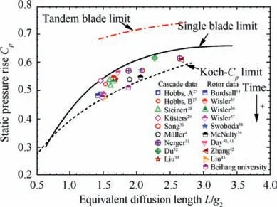
Fig. 2 Maximum static pressure rise of single-blade cascades,tandem-blade cascades and experimental data from open literatures.
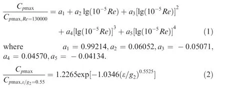
In the present study, the Reynolds number of 130000 is applied as the reference value. Different from the reference ε/gof Koch, the value is set as 0.022, which represents the common value in modern rotors with the medium tip clearance(1.40%of blade height)and low aspect ratio(around 1.20)and medium solidity (around 1.20).
The majority of the experimental data are above the Koch’s correlation, and almost all of them are below the limit of single-blade cascades. It is evident that the maximum static pressure rise of an individual row is able to be closer to the limit of a cascade with more skillful design methods, such as more advanced airfoil, reasonable radial distribution of aerodynamic loading, reasonable reaction and so on.
Besides, the Cof tandem-blade cascades depicted in Fig. 2 indicates that the tandem-blade cascade evidently extends the limit of pressure rise of the single-blade cascade.
Based on the models of the maximum pressure rise,an ideal E parameter is defined to evaluate the margin between the static pressure rise at design point(C)and the maximum static pressure rise calculated by the model,which is expressed in Eq.(3).

The smaller the E parameter is,the larger pressure rise margin a blade has.As shown in Fig.2,the tandem blade is potential to have a smaller E parameter. Hence, the Ewill be helpful to choose parameters in preliminary design.
3. Design of single-blade and tandem-blade stages
In the presented study, the stage loading coefficient (based on the blade tip rotating speed) is set as ψ=0.46(based on the mid-span rotating speed ψ=0.60),which is higher than typical conventionally loaded compressors. In order to balance the efficiency and stall margin, the preliminary design parameters, such as the flow coefficient and the reaction, must be chosen carefully.
3.1. Preliminary design tool
In order to analyze the effect of design parameters on the efficiency and the stall margin of single-blade stages,a preliminary design tool is utilized.In this tool,the repeating axial compressor stages is adopted,where the dimensionless velocity triangles are only dependent on flow coefficient (φ), loading coefficient(ψ) and reaction (R), as shown in Fig. 3. In Fig. 3, the number-type subscripts 1 and 2 mean the inlet and outlet ofthe rotor blade,respectively,and 3 means the outlet of the stator blade.Other nomenclatures are represented as follows:absolute velocity(c),relative velocity(w),absolute flow angle(α),relative flow angle(β),rotating speed(U).Several classical loss models are used in the tool, including blade-profile total pressure loss coefficient(ω)expressed by Koch and Smith,the secondary flow total loss coefficient (ω)proposed by Howell,the end wall total loss coefficient (ω) developed by Aungier and Farokhi,and the tip leakage total loss coefficient(ω)developed by Schweitzer and Garberoglio.For a rotor,the total loss is the sum of ω,ω,ωand ω,and for a stator with sealed hub,ωis not included.

Table 1 Main parameters of test case rotors.
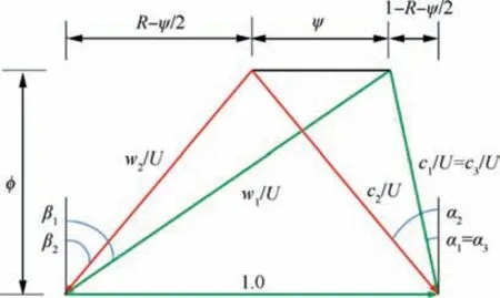
Fig. 3 Dimensionless velocity triangles for repeating axial compressor stages.
Table 2 gives the comparison between the predicted value using the preliminary design tool and experimental data of a conventionally loaded compressor.It can be seen that the tool is accurate enough to be used to determine the preliminary design parameters.
3.2. Choice of preliminary parameters
(1) Flow coefficient.The effect of the design flow coefficient on efficiency η and Eis shown in Fig.4.The optimal reaction and solidity were first determined and used forcalculating efficiencies for both the rotor and stator.Fig. 4 shows that the stage efficiency increases firstly and then decreases as the flow coefficient decreases.The maximum efficiency is about 90%at which the flow coefficient is about 0.50. However, the Eincreases with flow coefficient decreasing, which means smaller pressure rise margin.For a conventionally loading compressor, the average stage Eis generally not greater than 0.82, and Eof rotors is expected to be small if the efficiency is acceptable. To achieve a design efficiency of 90%and a wider working range,the flow coefficient was chosen as 0.55. Meanwhile, Eof rotors and stators are 0.90 and 0.74, and the stage efficiency is 90.1%.

Table 2 Comparison of results of predicted by model and experiment.
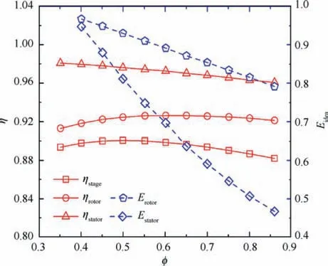
Fig. 4 Isentropic efficiency and E parameter of rotor and stator calculated by preliminary design tool.
(2) Reaction. It is well known that the compressor stage reaction has a vital effect on stage efficiency. Dickens and Dayhad investigated the choice of reaction for highly loaded compressor stages. The results showed that as the stage loading increases, reaction needs to increase to achieve the optimum efficiency. When ψ=0.46, the optimum reaction is approximately 0.73.In this case,the outflow angle of stator is negative.which is uncommon in the rear stage of high-pressure compressors. Hence, in this paper, the outlet flow angle is set as 0, the corresponding reaction of which is approximately 0.70.
(3) Solidity.The effect of the solidity on loss coefficient was also analyzed using the preliminary design tool. Fig. 5 shows the optimum solidity (σ) for different inflow(β), outflow angles (β) and Turning Angle(TA = β- β). In previous section, φ, ψ and R were chosen as 0.55, 0.60 and 0.70, respectively, and the flow angles of both the rotor and stator were calculated by repeating stage equation, as shown in Table 3. Therefore, the optimum average solidity for the rotor is around 1.90, and the optimum solidity for the stator is around 2.15.
Based on the preliminary design parameters, the velocity triangles were determined. Both rotor and stator blades were designed with the Controlled Diffusion Airfoil (CDA). The geometry parameters at different span were optimized by 3D numerical simulation Ansys CFX.And detailed design parameters are shown in Table 4.
3.3. Design strategy of tandem-blade stage
In order to make the tandem-blade and the single-blade designs comparable, two aspects are constrained. Firstly, they have almost the same preliminary design parameters,including the flow coefficient, the loading coefficient and the reaction,and the tandem blade works near the minimum-loss incidence at the design condition. Secondly, the radial distribution of velocity triangles is similar.Besides,the solidity of the tandem rotor is a little larger than the single rotor,which is 2.07,2.01,2.08 at the hub, the middle span and the shroud locations,respectively. The solidity of the tandem stator increases by 10%compared with the single stator at all spanwise locations,as shown in Table 5.
Compared with single blades, tandem blades have its own design parameters, including the Pitchwise Position (PP), the Axial Overlap (AO, as defined in Fig. 1), the loading split and the solidity ratio, which have important effect on the performance.Fig.6 shows the radial distribution of AO and PP of both rotor and stator blades.For rotor blades,PP is nearly 0.8 from the hub to the middle span. Due to the airfoils of different radiuses stacking along the center of gravity, PP decreases with radius increasing,and it is 0.70 at the shroud.The stagger angle from the hub to the shroud increases gradually, which means the axial chord is decreased. Therefore, AO of rotor decreases from around -0.007 to nearly -0.106 (the negative number means there is no axial overlap). For stator blades,PP is in the range of 0.80-0.85 at mainstream locations,which is near the minimum-loss PP for the 2D tandem cascades.However, at the endwall regions, PP decreases to around 0.7 to increase the mass flow through the nozzle formed by Front Blade(FB)and Rear Blade(RB),which is able to control corner separation of RB. AO of stator is around 0 at the entire span.
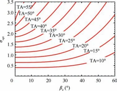
Fig.5 Optimum solidity of different inlet and outlet flow angles.

Table 3 Flow angles of rotor and stator calculated by repeating stage equation.
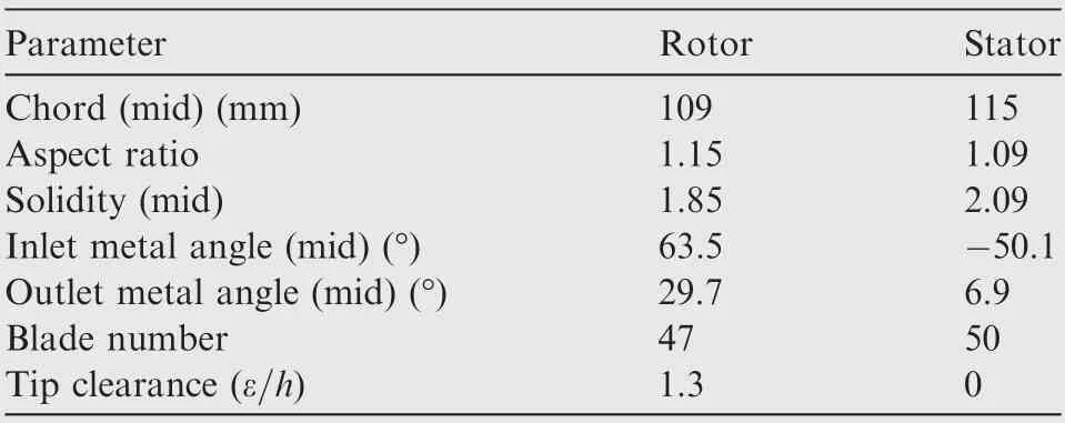
Table 4 Design parameters of single-blade stage.
Fig. 7 shows solidity ratio of FB (σ) and RB (σ). The solidity ratio of the tandem rotor(Σ=σ/σ)is in the range of 1.0-1.18, decreasing with the span increasing and it is almost 1.20 at all spanwise locations for the tandem stator.For the rotor blade, the loading coefficient of FB(ψ/(ψ+ψ)) is around 43.7% of the tandem blade at the design condition. For the stator blade, a circulation factor ξ is defined to describe the loading split(Eq.(4)).At the design condition, ξ is 0.485 for the tandem stator.

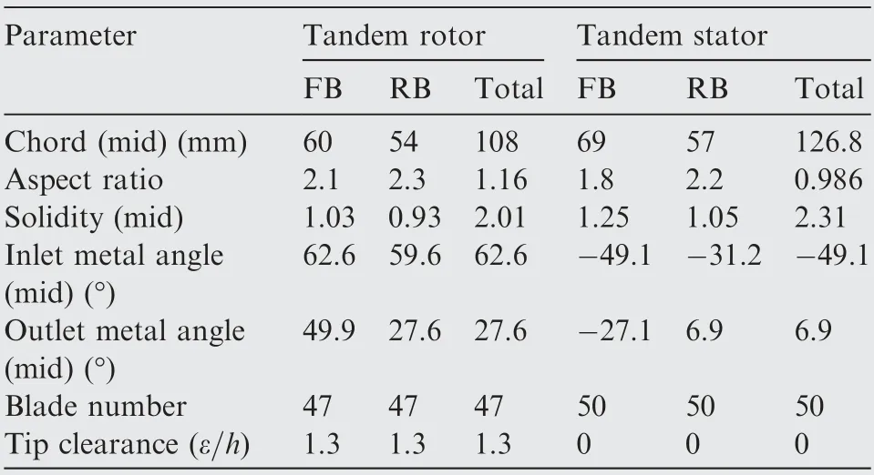
Table 5 Design parameters of tandem-blade stage.
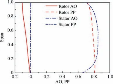
Fig. 6 AO and PP of rotor and stator blades.
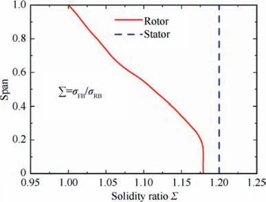
Fig. 7 Solidity ratio of FB and RB.
where the subscripts of 11, 22, 12 represent inlet of tandem blades, outlet of tandem blades and position between FB and RB, respectively. Vis the circumferential velocity and α is the flow angle.
The same as the conventional design,both the tandem rotor and stator blades are designed with the CDA airfoil. Detailed design geometry parameters are shown in Table 5.Fig.8 shows the 3D geometries of these two sages.It should be noticed that in the two stages,the S0 blades are the same as the single-blade stator, S1. Therefore, the inlet flow conditions of the two rotors are the same.
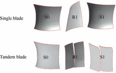
Fig. 8 3D models of single-blade stage and tandem-blade stage.
4. Experimental setup
4.1. Experimental facility
The experiment was conducted on a Low-Speed Large-Scale Axial Compressor (LSLSAC) test facility at Beihang University.The compressor is composed of Inlet Guide Vanes(IGV), stators (S0), tested stage (R1 + S1) and Outlet Guide Vanes(OGV),as shown in Fig.9.IGV and S0 provide the inlet flow condition like the multistage circumstance, and S0 is a copy of S1.OGVs turn the flow to the axial direction.The casing diameter is 1000 mm, and the hub-to-tip ratio is 0.75. All five blades are generated by 3D printing with the nylon material. The rotor is rotated at 1100 r/min, and the tip of all the stationary blades are sealed.Detailed introduction of the compressor tests can be seen in Ref. 49.
4.2. Measurement techniques
In order to obtain the performance and flow field of the compressor, several measurement planes are set up at different axial locations, as shown in Fig. 10. Six static pressure taps,uniformly distributed in the circumferential direction,are used to measure the inlet mass flow at Plane 0.Plane 1 is between S0 and R1,and Plane 2 is between R1 and S1.Plane 3 and Plane 4 are located at 30 mm and 220 mm downstream of S1,respectively.
Eight total pressure rakes are uniformly distributed in the circumferential direction at Plane 4 in order to measure the total pressure of the stage exit.Each total pressure rake covers 100% stator pitch width in the pitchwise direction. The efficiency of the compressor used in this study is based on the power of the motor, which is calculated by the measured torque and rotating speed, as shown in Eq. (5). The coefficient of total pressure rise is based on the dynamic head calculated by the blade rotating speed at the middle span,as shown in Eq.(6).

where the number-type subscripts mean locations of measurement. ηis the efficiency calculated by the specific heat ratio(k), the gas constant (R), the torque (M), the rotating speed(n), inflow total temperature (T), total pressure ratio (π) and mass flow (m) measured at Plane 0. Cis the coefficient of total pressure rise based on dynamic pressure head of midspan rotating speed (U), and it is calculated by the total pressure at Plane 1 (P) and Plane 4(P), density(ρ).
An L-shaped five-hole probe is used to measured pressure and velocity field at Plane 1, Plane 2 and Plane 3. At Plane 2, 33 measurement points from 2.4% span to 97.6% span and 14 measurement points in the pitchwise direction are arranged (covering 100% stator pitch width). The number of measurement points is increased to 19 at Plane 3 to obtain detailed flow fields, and there are more measurement points at the region of the blade wake, as shown in Fig. 11. Besides,considering the large flow angle range when the corner separation occurs, the zone method developed by Liu et al.was used to processed the measured data of the five-hole probe.
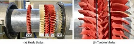
Fig. 9 Low-speed large-scale axial compressor test facility.
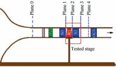
Fig. 10 Measurement planes at different axial locations.
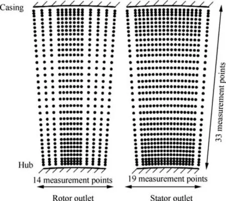
Fig. 11 Measurement points arrangement at rotor and stator outlet.
In the experiment,the pressure was measured with by a series of Rosemount 3051S pressure transducers, the measurement range and the accuracy of which are ±6.22 kPa and 0.025% full scale. And the pressure transducers were calibrated ahead of the experiment each time to guarantee the measurement accuracy. The temperature was measured by a thermocouple sensor located at the inlet of the experiment facility with the accuracy of±0.25 ℃.The measurement range and the accuracy of the torque detector used in the experiment are 500 N·m and 0.2% full scale. The control accuracy of the rotating speed is±0.5 r/min.As for the measurement accuracy of the five-hole probe, it can be seen in Ref. 50.
5. Comparison of performance characteristics
Fig. 12 shows the characteristics of the tandem-blade and single-blade stage, where the loading coefficient (ψ) and the compressor efficiency are plotted versus the flow coefficient.

where π is the total pressure ratio and ˙m is the mass flow.The subscript of "DE" is the design flow condition and and "S" is the stable operating condition closest to stall. For the singleblade stage, experimental loading coefficient is 0.448 at DE condition,2.6%less than the design target 0.46.Experimental compressor efficiency reaches 91.4% at DE condition, while the maximum efficiency is near 91.9%.Eq.(7)is used to assess the compressor Stall Margin (SM). The single-blade stage has an experimental stall margin of 16.9%. In contrast, the conventional loading coefficient stage (Ψ) experimented in this facility shown in Ref. 43 has a stall margin of 25.9% and a maximum efficiency of 91.8%. Hence, the highly loaded compressor is able to reach a maximum efficiency of more than 91% by selecting reasonable primary parameters, but the stall margin is much smaller than the conventionally loaded compressor.
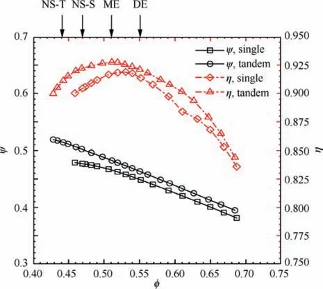
Fig. 12 Comparison of characteristics of single and tandem stages (DE: design point, φ = 0.55; ME: maximum efficiency,φ = 0.51; NS-S: near stall point of single stage, φ = 0.47; NS-T:near stall point of tandem stage, φ = 0.44).
Because the single-blade stage does not achieve the loading target,some compensation of loading is made for the tandemblade stage.For the tandem-blade stage,experimental loading coefficient is 0.463 at design condition, a little higher than the design target.The experimental compressor efficiency obtained by experiment is 92%at DE condition,which is 0.60%higher than the single-blade stage, and the maximum efficiency is 92.8% at about φ = 0.51, 1.0% higher than the single. When φ<0.51,the difference between the single-blade stage and the tandem-blade stage becomes much greater. At the near stall point of the single-blade stage,φ=0.47,the deviation of compressor efficiency is approximative 1.60%. Besides, the tandem-blade stage has an experimental stall margin of 22.3%, 5.4% higher than the single-blade stage. Therefore, it could be concluded that the tandem blade is able to improve the stall margin for highly loaded compressor designing while maintaining an acceptable design efficiency.
In order to further illustrate the advantages of tandem blades, the loading versus the efficiency is plotted in Fig. 13.The efficiency of the tandem blade is less than the single blade at lower loading coefficients (ψ<0.415), and when ψranges from around 0.415 to 0.46, there is little difference.When ψ>0.46, the tandem blade has obvious advantages over single blade. Hence, the loading coefficient of 0.46 could be regarded as the critical point.In addition,the loading coefficient of the tandem blade at the maximum efficiency is approximate 0.48, while the single blade is 0.46. The highest loading coefficient of tandem is up to 0.52,which is 0.04 higher than single blade. If the loading coefficient of maximum efficiency is used as datum, the loading margin of the tandem blade is around 8.3%, nearly twice of the single blade.
6. Effect of tandem-blade compressors on loading limit
6.1. Comparison of pressure rise and E parameter
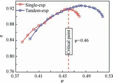
Fig.13 Comparison of efficiency at the same loading coefficient.
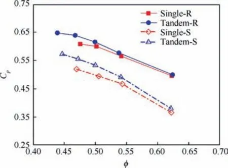
Fig. 14 Experimental Cp of single and tandem blades at typical flow coefficients.
Fig.14 shows the experimental average Cof the single and the tandem blades at typical flow conditions,which were measured by five-hole probe before and after blade rows (in Fig. 14, R represents rotors and S represents stators). At all conditions,Cof the tandem rotor is higher than that of the single rotor,reaching the maximum at Near Stall(NS)condition.The peak static pressure rise of the tandem rotor is around 8.3% higher than that of the single rotor, while the stator is 10.2% higher.
Fig.2 has shown the pressure rise limits of the single-blade and tandem-blade cascade, which is related with aerodynamic and geometric parameters. The experimental static pressure rise coefficients of the single rotor and the tandem rotor at DE and NS conditions are compared with the model as shown in Fig. 15. For the highly loaded single rotor, the peak static pressure rise is close to the limit predicted by the model, and for the tandem rotor, the peak static pressure rise is not only higher than the single rotor, but also exceeds the limit of the single-blade cascade.
The conventionally loaded single rotor of ψ= 0.30is also shown in the graph with actual E parameter of rotor,which is defined as C/C, being 0.81. For the highly loaded designs, the actual E parameter of the single rotor is 0.92 and the actual E parameter of the tandem rotor is 0.86.Although the actual E parameter of the tandem rotor does not reach that of the conventionally loaded rotor, the tandem blade has shown the potential to broaden the margin for highly loaded compressors.
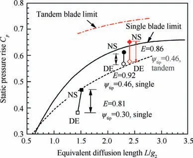
Fig. 15 Experimental Cp and E parameter of single and tandem rotors.
The experimental static pressure rise coefficients of the single stator and the tandem stator at DE and NS conditions are compared with the model as shown in Fig. 16. The graph shows that L/gof the tandem stator is larger than the single stators,mainly caused by the larger solidity.It can be seen that the tandem stator increases the static pressure rise of the single stator by 10%at NS condition.The actual E parameter of the single stator is 0.89, while that of the tandem is 0.85. Besides,Cat NS condition is far away from the limit predicted by the models for both tandem and single stators. Actually, in order to satisfy the stage efficiency and decrease the loss of stators,the matching incidence of both stators is chosen as the larger negative angle, so Cof both stators do not reach the peak value. Moreover, the compressor reaction for highly loaded compressors is generally greater than 0.60, which means more static pressure rise is obtained from rotors. Therefore, the stators do not work at peak pressure rise conditions when the compressor stage stalls.
The experimental Cof the single and tandem blades at 0.25 (near hub), 0.50 (mid-span) and 0.80 (near shroud) span are shown in Fig.17.The static pressure rise decreases for both the single and tandem rotors with the spanwise location increasing. The maximum static pressure rise of the single rotor is at 0.25 spanwise location, and reaches the limit predicted by the model. Considering the different flow features at the hub, midspan and shroud, the pressure rise is hardly possible to reach the maximum at the same conditions. The pressure rise of the tandem rotor is larger than that of the single rotor at all spanwise locations, and the maximum value is close to the limit predicted by the model, too. The relation between the distribution of the single stator and the tandem stator is same with that of the rotor,but the distribution of static pressure rise of the stators is more uniform than the rotors.The distribution indicates that the pressure rise potential of airfoils at the entire span is utilized.
6.2. Factors restraining increase of pressure rise for tandem blades
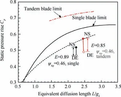
Fig. 16 Experimental Cp and E parameter of single stators and tandem stators.
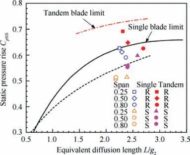
Fig. 17 Experimental CpNS of single and tandem blades at different spans.
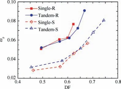
Fig. 18 Variation of experimental loss parameter with diffusion factor of single and tandem blades.
It needs to be noticed that the mass flow-averaged Cof the tandem blade at NS condition is a bit smaller than the tandem-blade limit, especially for the stator. Fig. 18 shows variation of loss parameter(ω)with different diffusion factor of single and tandem blades. As presented by McGlumphy et al.tandem cascades have advantage of loss reduction at high DF. In the presented study, the tandem rotor does show this advantage of loss reduction, but the tandem stator does not. Fig. 19 shows the dimensionless axial velocity measured at the exit of stators at NS conditions (in Fig. 19, Vis axial velocity; PS and SS mean Pressure Surface and Suction Surface, respectively). Compared with the single blade, the secondary flow feature of the tandem blade is more complicated due to the interaction of FB and RB. In hub regions, the FB corner separation moves along the radical direction to the mid-span, causing a large flow blockage and high loss. The complicated flow features at the endwall regions restraint the increase of the static pressure rise at NS conditions.Therefore,it must be paid more attention to endwall flow for the design of tandem stages.
So far, the inconsistency in open literatures has been clarified: the tandem blade could broaden the stall margin for highly loaded compressors and reach a higher maximum efficiency compared with comparable single blades. The peak pressure rise of tandem rotors exceeds the limit of singleblade cascades, indicating the potential of tandem blades to break the loading limit of traditional axial compressors.
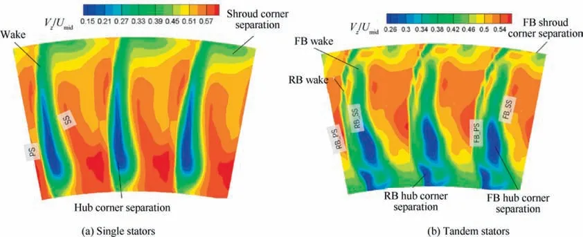
Fig. 19 Contours of dimensionless axial velocity at exit of single and tandem stators at NS conditions.
7. Conclusions
(1) The potential of tandem blades to break the loading limit of subsonic highly loaded axial compressors is investigated experimentally in this paper.The 2D model of the maximum static pressure rise derived in previous work is validated by a large amount of experimental data,and these data are in good agreement with the predicted models. Based on the theoretical models, an E parameter is defined to evaluate the stall margin.
(2) In order to show the potential of tandem blades,a highly loaded single-blade compressor stage (ψ=0.46) is designed to be regarded as the baseline case.The preliminary design parameters are selected carefully under the guidance of the efficiency models and the E parameter.The radical distributions of these parameters are optimized to achieve high efficiency and wide working range.A tandem-blade stage is designed with the similar radical distribution of velocity triangles for each blade.PP,AO,loading split and solidity split are optimized to guarantee the efficiency and the stall margin.
(3) Experimental results indicate that tandem blades have advantages in stall margin and efficiency at small flow coefficient. The maximum efficiency of the tandemblade stage is 1% higher than the single-blade stage and the stall margin is increased from 16.9% to 22.3%. Compared the efficiency at the same loading coefficient, the critical point of the loading coefficient,where the tandem blade begins to show superiority, is around ψ=0.46.
(4) The static pressure rise of tandem rotors at the near stall condition is even beyond the pressure rise limit of conventional 2D cascades. It is proved that tandem blades are able to increase the stall margin for highly loaded compressors and reach a higher maximum efficiency compared with comparable single blades. The experimental results also indicate the potential of tandem blades to break the loading limit of conventional axial compressors, which strongly supports the application of tandem blades in highly loading compressors if required. Besides, the secondary flow in tandem blades,is more complicated,restraining the increase of pressure rise, especially in stators. Therefore, the endwall flow should be paid more attention for tandem blades.
The authors declare that they have no known competing financial interests or personal relationships that could have appeared to influence the work reported in this paper.
The authors would like to acknowledge the support of National Natural Science Foundation of China (Nos.51806004 and 51790511) and National Science and Technology Major Project, China (No. 2017-II-0001-0013).
 Chinese Journal of Aeronautics2022年4期
- Chinese Journal of Aeronautics的其它文章
- Reduced-dimensional MPC controller for direct thrust control
- A multiscale transform denoising method of the bionic polarized light compass for improving the unmanned aerial vehicle navigation accuracy
- Periodic acoustic source tracking using propagation delayed measurements
- Optimal predictive sliding-mode guidance law for intercepting near-space hypersonic maneuvering target
- Sea fog detection based on unsupervised domain adaptation
- Unsteady characteristic research on aerodynamic interaction of slotted wingtip in flapping kinematics
