A multiscale transform denoising method of the bionic polarized light compass for improving the unmanned aerial vehicle navigation accuracy
Donghu ZHAO,Jun TANG,Xindong WU,Jing ZHAO,Chengung WANG,Chong SHEN, Jun LIU,*
a Key Laboratory of Instrumentation Science & Dynamic Measurement, Ministry of Education, School of Instrument and Electronics, North University of China, Taiyuan 030051, PR China
b School of Information and Communication Engineering, North University of China, Taiyuan 030051, PR China
KEYWORDS Denoising;Multi-scale transform;Orientation;Polarized light compass;UAV navigation
Abstract In recent years, the bionic polarized light compass has been widely studied for the unmanned aerial vehicle navigation.However,it is found from the obtained investigation results that a polarized light compass with a sensitive and high dynamic range polarimeter still provides inferior output precision of the heading angle due to the presence of the noise generating from the compass.The noise is existed not only in the angle of the polarization image acquired by polarimeters but also in the output heading data,which leads to a sharp reduction in the accuracy of a polarized light compass. Herein, we present noise analysis and a novel multiscale transform denoising method of a polarized light compass used for the unmanned aerial vehicle navigation. Specifically, a multiscale principle component analysis utilizing one-dimensional image entropy as classification criterion is directly implemented to suppress the noise in the acquired polarization image.Subsequently,a multiscale time-frequency peak filtering method using the sample entropy as classification criterion is applied for the output heading data so as to further increase the heading measurement accuracy from the denoised image above. These two approaches are combined to significantly reduce the heading error affected by different types of noises.Our experimental results indicate the proposed multiscale transform denoising method exhibits high performance in suppressing the noise of a polarized light compass used for the unmanned aerial vehicle navigation compared to existing prior arts.
1. Introduction
Bionic polarization navigation imitating the guided behavior of animals in nature, particularly arthropods such as desert ants,migrating birds,insects,and so on,which specifically utilizes the polarization pattern of the skylight, is widely researched in the Unmanned Aerial Vehicle(UAV)navigation recently.The Angle of Polarization(AoP)distribution in the polarized sky light possessing strong anti-interference and robustness can provide firm and crucial information for UAV navigation due to less affecting by anthropic factors.This line of investigation has been applied to the real-time calculation of the heading angle in terms of the relative angle between the forward direction of a carrier and the reference datum based on the symmetry axis of atmospheric polarization pattern.Compared with the commonly used navigation methods such as the Global Position System(GPS)or Inertial Navigation System(INS),the bioinspired polarized light compass,whose information source is natural,can output heading information autonomously and stably for unmanned platforms,such as UAVs and unmanned vehicles.
Although polarization sensitivity and high dynamic range have been involved in various imagers, a polarized light compass integrated with polarimeters still provides inferior output precision of the heading angle due to the presence of nonpolarization-related components such as noise.The noise existing in the compass is distinct,which is generated not only from AoP images acquired by current up-to-date polarimeters but also from the output data of heading angles. In view of image noise, current state-of-the-art denoising strategies are realized for grayscale and monochromatic images and a Principal Component Analysis (PCA)-based denoising method is proposed for color filtered images and Division of Focal Plane polarimeter (DoFP) images.Results of signal-to-noise analysis, theoretical estimation, and measurements based on Stokes parameters in DoFP have been achieved.In addition,to minimize Poisson shot noise for Stokes polarimeters, the optimal method combining the polarimeters optimization for additive noise together with architecture equalization in variable noise has been addressed.Other newly alternative learning methods based on the residual dense network for polarimetric images(PDRDN),a Block-Matching and 3-D(BM3D)filtering algorithm,K-times Singular Value Decomposition(K-SVD)and a hybrid denoising algorithm based on BM3D and KSVD are used for Gasssian noise in DoFP polarization images (BM3D- KSVD),in which facilitate image processing and content expressing by all the different polarization channels simultaneously. It can be concluded that the hybrid method based on multi-scale decomposition has superiority image denoising effect. In addition, compared to SVD algorithm, the PCA algorithm has the advantage of lower computation load, which can facilitate the operation of image denoising. Accordingly, the improved PCA image denoising method based on multi-scale decomposition is studied in our work.
Apart from a great quantity of noise resulted from the AoP image,it is necessary for heading data denoising for the bioinspired polarized light compass applied for UAV navigation due to the superimposed noise from the hardware acquisition system of a compass, which causes a sharp decline in the navigation precision. The wavelet threshold and Empirical Mode Decomposition (EMD)signal denoising methods based on nonlinear and nonstationary data analysis have been studied recently, which decompose a complicated data set into a finite number of Intrinsic Mode Functions (IMFs) and then the high-frequency noise can be eliminated.Time-Frequency Peak Filtering(TFPF)can distinguish the valid signal components and encode them as an Instantaneous Frequency (IF),thus serving as an effective technique for noise reduction and signal enhancement.In addition, since the TFPF algorithm shows the superiority in data denoising, some improved TFPF-based algorithms have been proposed, such as TFPFEWT algorithm.Although the improved TFPF-based denoising algorithms have excellent denoising effects, the adaptive determination method of TFPF parameters still need to be studied. Besides, the denoising method application in a polarized light compass has not been reported. Consequently,the improved TFPF-based denoising method and its application in a polarized light compass are studied furtherly in this work.
In this paper, to improve the heading performance of a polarized light compass for UAV navigation,a comprehensive denoising method is proposed. Image denoising and data denoising are performed simultaneously to obtain the best denoising effect. With the objective of realizing significant improvement of the heading accuracy on UAV navigation process, our main contributions in this paper are as follows:
(1)A novel Multiscale Transform(MST)denoising method for a bioinspired polarized light compass used for UAV navigation is presented, where a multiscale principle component analysis (MS-PCA) is directly implemented to suppress the noise in AoP images. First, two-dimensional empirical mode decomposition (BEMD) is employed to decompose the original noisy AoP image into multiple image IMFs, and then a PCA based on a principle component contribution rate is introduced to denoise each scale IMF including solar meridian information utilizing one-dimensional image entropy (1D-IE)as classification criterion,which achieves an effective denoising result of AoP images.
(2)We exploit a Multiscale Time-Frequency Peak Filtering method (MS-TFPF) for removing the noise in the heading data output from a polarized light compass, in which the output data is decomposed into distinct IMFs by Ensemble Empirical Mode Decomposition (EEMD). The decomposed IMFs are classified into different scales using the Sample Entropy (SE) as classification criterion, and the noisy IMFs are filtered by TFPF in subdivision scale, which can reduce the noise influence on the whole output heading data significantly.
(3) The static, rotation, and UAV flight experiments are designed and carried out to verify the effectiveness of the proposed MST denoising method. Compared with various prior arts, the experimental results demonstrate the proposed MST denoising method can more effectively suppress the noise of a bionic polarized light compass for improving UAV navigation accuracy.
The remainder of this paper is organized as follows. The noise analysis of a polarized light compass is presented in Section 2. Section 3 presents the proposed MST-based denoising algorithm. Experiments and comparison are described in Section 4. Finally, the conclusion of the paper is presented in Section 5.
2. Noise analysis
A comprehensive analysis of the polarized light compass noise components is useful for optimizing AoP images acquired by polarimeters and the essential data associated with heading so that significant accuracy improvements of the output heading information are ultimately achieved in UAV navigation.Currently, the existing approaches to calculate the heading angle are over-simplified by assuming either zero noise or an insufficient number of noise sources,which will lead to a rapid decline in the heading measurement accuracy.To address these issues, it is necessary to investigate comprehensive noise analysis and contributions for the polarized light compass before introducing a novel de-noising architecture.
In a polarized light compass, the main contributions to noise incorporate compass photon and electronic fluctuations along with conversion from analog-to-digital. Due to the intrinsic quantum nature of light, the noise yielded by the uncertainty in the count of rich incident photons is known as photon shot noise.Similarly, an asynchronous response to all pixel dimension shrink as the trend toward a state-of-theart color polarization sensor will still result in the noise called photo-response non-uniformity.Related to the exposure time and temporal invariant elements, dark current nonuniformity is generated by different pixels, which is termed as dark current shot noise.The first three types of the noise described above result from the modulation of the channel conductance.Consequently,they exist in AoP images acquired from the polarized light compass.
Furthermore,the noises generated from the compass circuit design notably increase including the readout electronics thermal noise, low-frequency flicker noise—which is referred to as 1/f noise,random telegraph signal noise,and row and column noise.The analog-to-digital signal conversion in the compass system results in remarkably high quantization noise. These types of noises exist in the heading data output from a polarized light compass. Row noise emerging in a polarized light compass, which is composed of temporal and fixed offsets,originates from all given pixel rows released from reset. The fixed components can be eliminated by follow-up color reconfiguration, whereas the temporal components appear in the compass. Column noise is produced by the resetting of sample-hold capacitors and mismatch between column amplifiers and the vertical lines of a polarized light compass.Conclusively,an integrated noise model of the polarized light compass is shown as Fig. 1, and the noise components are summarized in Table 1.
3. Proposed MST denoising scheme
In spite of existing various image and data denoising approaches addressed above, we focus specifically on a novel MST denoising scheme because of its capacity of more effectively suppressing the highly complex noise of a polarized light compass. In particular, an MS-PCA image denoising method based on BEMD is directly implemented on suppressing the noise in AoP images since it is able to decompose a noisy image into different IMFs and eliminate noise corresponding to the different IMF scales. Furthermore, to continuously increase the accuracy of heading angles calculated from the denoised images, an MS-TFPF approach is employed for the heading angle data output from a polarized light compass,where the EEMD method is adopted to divide the noisy data into different IMFs and a corresponding TFPF method is used to eliminate the noise in subdivision IMFs.

Fig. 1 Noise model of the polarized light compass.

Table 1 Noise components of polarized light compass.
3.1. MS-PCA method
AoP images acquired with polarization cameras are severely affected by the various types of noises described in Section 2,which leads to not only degrading the AoP image quality but also reconstructing false polarization information. Consequently, how to eliminate the noise in AoP images is a crucial issue having to be coped with. In this study, an MS-PCA method based on BEMD is proposed and directly implemented on AoP images to reduce noise. BEMD decomposes the noisy AoP image into a series of IMFs with different frequencies from high to low, which are then classified by onedimensional image entropy (1D-IE). The high-frequency IMF is valuable because it comprises abundant solar meridian information. A principle component contribution rate-based PCA denoising algorithmis employed for each IMF containing solar meridian information, and other IMFs are discarded directly. Finally, a denoised AoP image is achieved by reconstructing. The steps of the MS-PCA method are described as follows.
Step 1.Decomposition.BEMD is applied to decompose the noisy AoP image into IMFs IMF(x,y)and a residual component r(x,y)so as to achieve an adaptive multi-resolution analysis of each mode. Accordingly, the original AoP image is expressed as

where x and y indicate the two dimensions of the noisy AoP image f(x,y),respectively,and L implies the number of IMFs.r(x,y) is the residual component.
Step 2. Classification. To extract valuable solar meridian information and decrease computational load in denoising each IMF, 1D-IE is introduced to separate the series of IMFs into two components,namely Solar meridian-dominated IMFs(S-IMFs) and Non-Solar meridian-dominated IMFs (NSIMFs). The classification method is based on the interval similar values of 1D-IE, i.e., the values of 1D-IE with continuous similarity characteristics from low to high frequency can be regarded as the NS-IMFs since the value of 1D-IE would be varied sharply when the solar meridian information appears in the IMF.
Image entropy is a statistical form of features, which reflects the average amount of information in an image. The 1D-IE represents the amount of information involved in the aggregation feature of the grayscale distribution in images and is given by

where Pdenotes the proportion of pixels with gray value in images. The greater entropy H indicates the more abundant contour information; conversely, the lower H implies the less useful signal.

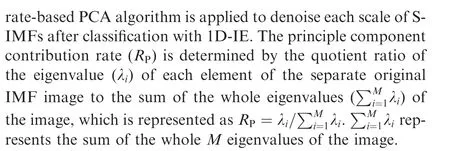
Step 4.Denoising.The corresponding PCA is employed for each IMF scale of the S-IMFs,and other IMFs are discarded.
Step 5. Reconstruction. The denoised AoP image is achieved by reconstructing the processed S-IMFs.
The algorithmic flow of the proposed MS-PCA image denoising is shown below, and the overall AoP image denoising procedure is shown in Table 2.
The heading angle data calculated by the denoised AoP images need to be output from a polarized light compass,therefore, the noisy data will be produced and handled with MS-TFPF algorithm subsequently.
3.2. MS-TFPF method
In this section,we introduce MS-TFPF algorithm to eliminate the noise in heading angle data output from a polarized light compass. MS-TFPF offers an adaptable time-varying characteristic that is highly available to key data denoising techniques implemented for the heading angle data, where TFPF briefly combined with ensemble empirical mode decomposition is exploited for the classified data by the sample entropy.The proposed MS-TFPF algorithm involves the following steps.Step 1. Noise Addition. The heading angle data S(t) with white noise is achieved by adding a random white noise series n(t) with normal distribution to the output heading angle data S(t),which can be modeled by

Step 2. Decomposition. S(t) is decomposed into L unseen IMFs I(t) and residual signals r(t) by EEMD, which can sift the optimum IMFs by the average of the ensembles of EMD and avoid mode aliasing in conventional EMD. Therefore, S(t) is represented by
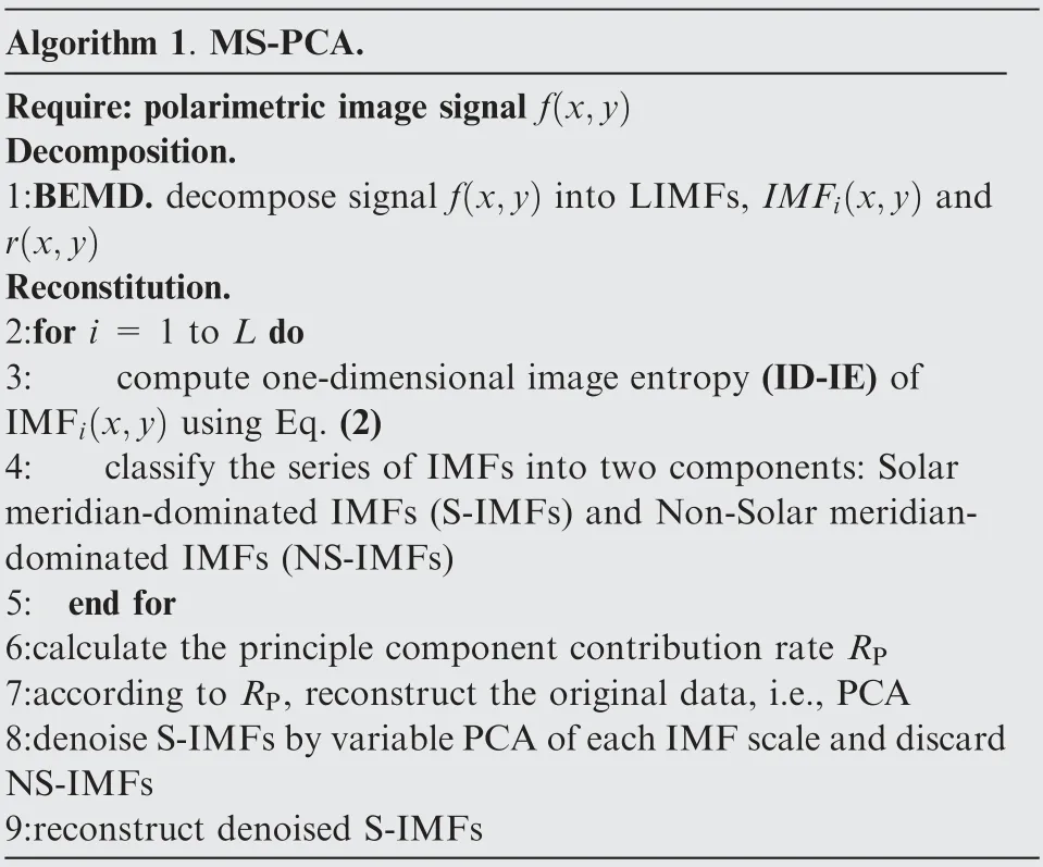
Table 2 Flow of the proposed MS-PCA algorithm.

Step 3. Classification. The Sample Entropy (SE) which is capable of examining time series for similar epochs is calculated for separate mean IMFs. For this purpose, the SE(m,r)of each mean IMF is calculated as follows, where r is the tolerance window and m is the run length. A and B denote two finite point sets.

Hence,numerous mean IMFs can be classified on the basis of the similar value of SE into Low-Frequency True signal Components (LFT-C), Hybrid Components (H-C), and High-Frequency Noisy Components (HFN-C).
Step 4. Judgment. It is extremely critical to adopt suitable TFPF for each mean IMF of LFT-C and H-C to suppress noise effectively. There is a contradiction before using the TFPF denoising method; that is, using TFPF for all the decomposed IMFs may result in more computation load but effective noise reduction, whereas using TFPF for several selected IMFs may result in limited noise attenuation but less computation load. To achieve a good tradeoff between preserving valid components to a great extent and reducing noise effectively, another important issue to be settled is how to adaptively apply corresponding TFPF for each different IMF of LFT-C and H-C after BEMD.
Here,a novel adaptive TFPF threshold selection method is proposed to judge and select the corresponding TFPF with different threshold parameters. The Reference Threshold (RT) is used as a determination criterion and can be obtained by comparing the difference between the data before and after denoising LFT-C.If the difference is bigger than the pre-set threshold θ,the value of RT is adjusted until θ is reached.The threshold θ is defined as Eq.(6)by experience,where u is LFT-C and q is the length of u.

The threshold Tof H-C is determined by the ratio of the SE of LFT-C and H-C together with RT. The TFPF adaptive threshold selection method is manifested using the flowchart shown in Fig. 2.
Step 5.Denoising.Based on Fig.2,we make full use of the flexible characteristics of the corresponding TFPF; that is,short-window TFPF is used for LFT-C to hold the valid data as much as possible, and long-window TFPF is used for H-C so as to decrease the noise as much as possible, and finally the HFN-C is eliminated directly.
Step 6. Reconstruction. The denoised heading angle data are obtained after reconstructing the denoised LFT-C and H-C.
The algorithmic flow is shown as follows and Table 3 shows the flow-process diagram of the proposed MS-TFPF algorithm.
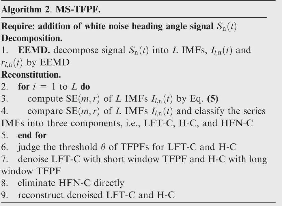
Table 3 Flow of the proposed MS-TFPF algorithm.
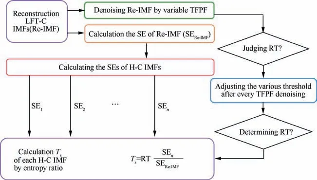
Fig. 2 Flowchart of adaptive TFPF threshold selection method.
4. Experimental results and analysis
4.1. Experimental setup
Static, rotation, and UAV experiments were conducted to achieve true AoP images and heading angle data using a selfproduced polarized light compass that incorporates an IMX250MZR polarization camera with a Nvidia Jetson TX2 embedded processing unit set up on a TBR100 three-axis turntable for static and rotation output acquisition(Fig.3(a)).The UAV flight test device shown in Fig. 3(b) comprises the reference system with Fiber Optic Gyro INS, GNSS receiver, a polarized light compass, and a UAV. True AoP images were captured with the polarization camera straightforward and the heading angle data were gathered with the polarized light compass not only by turntable rotation setup but also by the UAV experiment equipment. The whole experimental equipment of heading measurement and its characteristics are shown as Table 4.
4.2. AoP image denoising results and analysis based on heading angle experiment
To verify the effectiveness of the proposed MS-PCA image denoising scheme,BEMD was first used to decompose original noisy AoP images acquired from the compass into ten IMFs(i.e., IMF1, IMF2, IMF3, ..., IMF10) and a residual component. The key parameter of BEMD is the number of IMF,which is set as 11 and the whole decomposed result is shown as Fig. 4. Clearly, the solar meridian information in IMF1 is abundant and more than in IMF2. The detailed information progressively decreases from IMF3 to the residual component.
For using One-Dimensional Image Entropy (1D-IE) effectively to divide the decomposed IMFs and a residual component into valuable S-IMFs and NS-IMFs, first, the values of 1D-IE of every decomposed IMFs and a residual component were calculated and shown as Table 5. Subsequently, the similar values of 1D-IE of IMFs were determined by the interval similarity. According to this changed law, the series of IMFs were sorted into S-IMFs from IMF1 to IMF5 and NS-IMFs from IMF6 to the residual component. At last, the PCAbased denoising method was applied for each scale IMF of S-IMFs and the NS-IMFs are discarded.The complete parameter settings of the MS-PCA denoising method are listed in Table 6 and the denoised result of the AoP image is shown in Fig. 5.
The Mean Gradient(MG)and Standard Deviation(SD)of AoP images before and after denoising by the static test with various algorithms are compared in Table 7.A larger MG suggests a clearer image, while a smaller SD implies the existence of a small difference between the average value and the corresponding AoP images. Table 7 reveals that the proposed MSPCA denoising algorithm shows optimum performance in eliminating the heading angle noise comparing to existing prior arts, such as BM3D, PDRDN, and BM3D- KSVD. In particular, the classic criterion, i.e., Signal-to-Noise Ratio (SNR),needs to compare the original signal and the signal before and after denoising. Since the images and data in this study are real images and data by measurements, it is impossible to use SNR index to estimate the performance of the proposed MST method.Consequently,MG and SD are used to estimate the performance of the image denoising method.
Furthermore,Fig.6 shows the experimental results of heading angle measurements obtained by the proposed MS-PCA and other AoP image denoising approaches in the static test.It can be clearly seen that the heading error has been decreased effectively by the proposed MS-PCA image denoising method since the noisy components of AoP images can be extracted effectively after BEMD process and then reduced by the principle component contribution rate-based PCA denoising method.
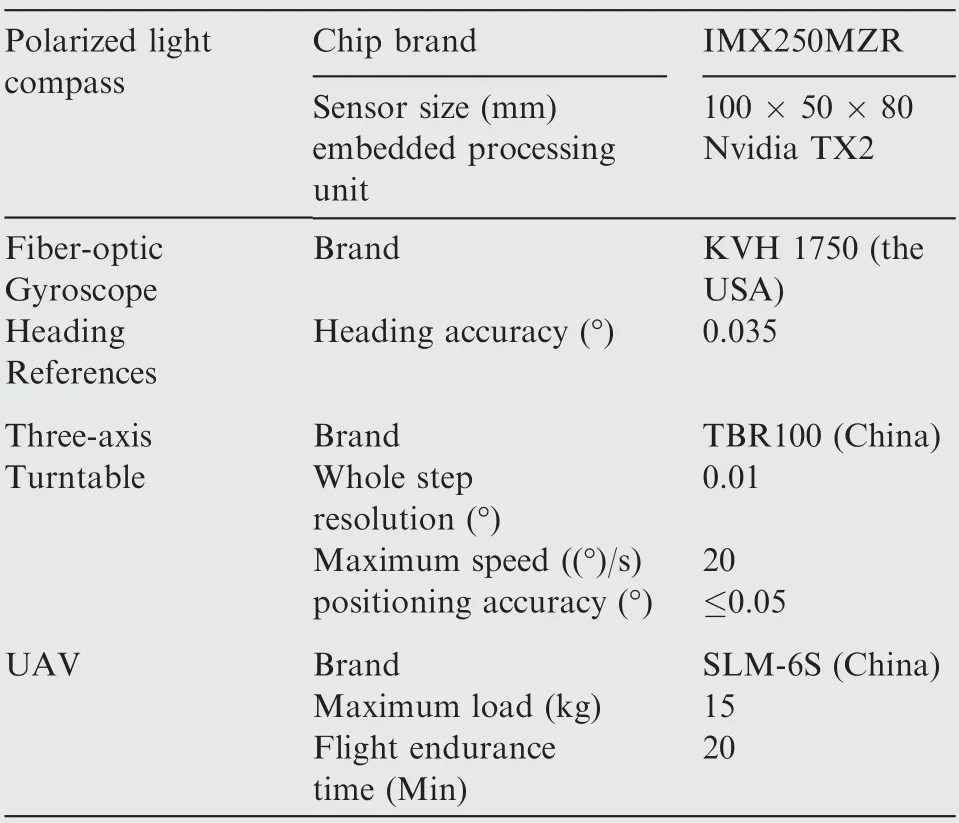
Table 4 Characteristics of the experimental equipment.

Fig. 3 Experimental setup for rotation, static, and UAV flight tests.
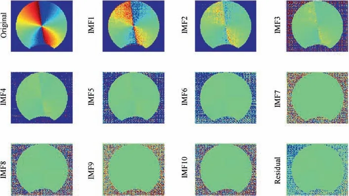
Fig. 4 Original and IMFs of AoP image.

Table 5 Values of 1D-IE of every decomposed IMFs and a residual component.

Table 6 Complete parameter settings of MS-PCA.
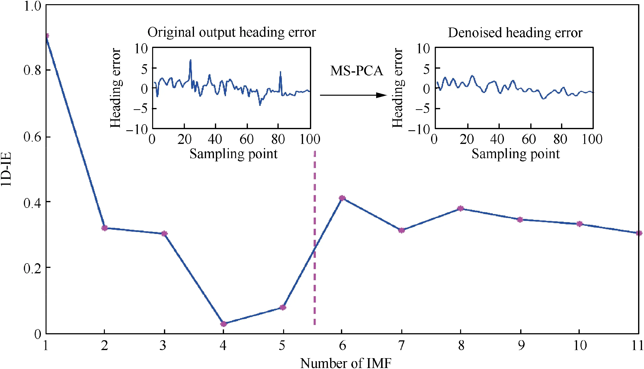
Fig. 5 Classified IMFs and denoising procedure of MS-PCA for S-IMFs.
The mean,SD,and root mean square error(RMSE)of the heading angle of static signals obtained after various image denoising algorithms are compared in Table 8. The BM3D method can attenuate some of the AoP image noise, but the SD and RMSE of the denoised results are still relatively high,suggesting that the BM3D has limited denoising ability for images. The PDRDN and BM3D-KSVD methods performed better than the BM3D. From Table 8, the Mean, SD, andRMSE of the heading angle error of the proposed MS-PCA are 0.0242, 0.3470, and 0.3453 lower than those of the BM3D, PDRDN, and BM3D-KSVD, respectively, which implies that the MS-PCA reduces the noise in AoP images significantly while retaining useful solar meridian information for heading measurements of the polarized light compass.
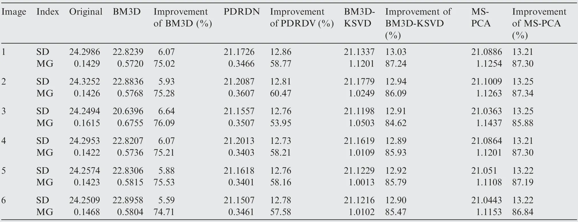
Table 7 MG and SD of AoP image static test with various denoising algorithms.
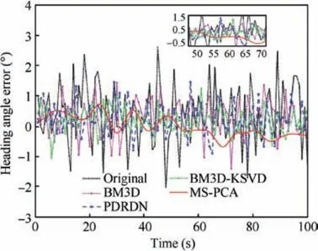
Fig. 6 Heading angle error comparison results of static test by using various image denoising algorithms.
4.3. Data denoising results and analysis based on heading angle experiment
As described in Section 4.2, we suppress the noise in AoP images. To achieve more gains on the heading accuracy for UAV navigation, various experiments were conducted to verify the effectiveness of the proposed MS-TFPF denoising scheme.
4.3.1. Rotation experimental and comparison
In this section, various experimental comparison and analysis are applied to the heading angle data with respect to different data denoising algorithms together with original data. The outdoor rotation experiment was conducted in the campus of North University of China (NUC) in Taiyuan City Shanxi Province on May 7, 2020, at sunset (from 15:30 to 17:00).The three-axis turntable was placed on the playground of the NUC campus.
Fig.7 depicts the rotation experimental results,from which it can be found that the true heading angle signal is completely submerged into the noise of the polarized light compass analyzed in Section 2. Consequently, it is tremendously necessary to suppress the noise to enhance the true signal.
EEMD is first used to decompose the output heading angle data into seven mean IMFs and a residual component. The whole decomposed result is shown as Fig. 8. The complete parameter settings of EEMD are mean square error of added Gaussian white noise and total average times, which are 0.3 and 300, respectively. Processing each decomposed IMF by a traditional approach with seven filters would lead to high computation load.To improve the computation efficiency without affecting the following procedure,the SE of each mean IMF is calculated by Eq. (5) and shown as Table 9. The IMFs based on the similar SE value are classified into LFT-C, H-C, and HFN-C,as shown in Fig.9.Subsequently,long-window TFPF according to an adaptive TFPF threshold selection methodintroduced in Section 3.2 is adopted to denoise the H-C so as to reduce noise effectively and short-window TFPF is used for LFT-C to reserve the valid signals while directly eliminating HFN-C. Finally, the denoised H-C and LFT-C are reconstructed to obtain the final denoised heading angle signal.The complete parameter settings of the MS-TFPF denoising method are listed in Table 10 and the denoised data result is shown in Fig. 9.

Table 8 Mean, SD, and RMSE of denoised heading angle error of static signal.
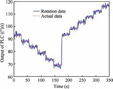
Fig. 7 Rotation experiment results of an ensemble polarized light compass.
Fig.10(a)and(b)elucidate the denoised heading angle and error results obtained by the proposed MS-TFPF and other data denoising approaches in the rotation test, such as TFPF,RLowess,and TFPF-EWT.Due to the denoised heading angle data is decomposed by EEMD into LFT-C,H-C,and HFN-C,the long-window TFPF according to an adaptive TFPF threshold is adopted to denoise the H-C and the shortwindow TFPF is used for LFT-C while directly eliminating HFN-C. In this way, the heading data noise can be attenuated purposefully. In addition, the spike noise of the heading angle appears inevitably during the turntable rotation, as shown in Fig. 10(a) and (b), which can also be suppressed effectively by the proposed MS-TFPF algorithm due to the spike noise can be extracted by EEMD processing and then eliminated by the adaptive TFPF algorithm. Consequently,the heading error has been decreased significantly with the proposed MS-TFPF by suppressing the noise in the output data from a polarized light compass.
The mean,SD,and RMSE of the heading angle of the rotation signal of various denoising algorithms after image denoising are compared in Table 11. The Mean, SD and RMSE of the MS-TFPF algorithm are the smallest of 0.0900, 1.2383 and 1.2365.This suggests the superiority of the proposed algorithm over existing denoising methods with respect to the heading angle accuracy improvement.
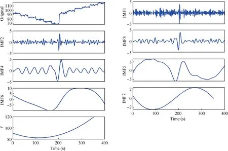
Fig. 8 Mean IMFs gained after the rotation signal decomposition by EEMD.

Table 9 Values of SE of every mean IMFs.
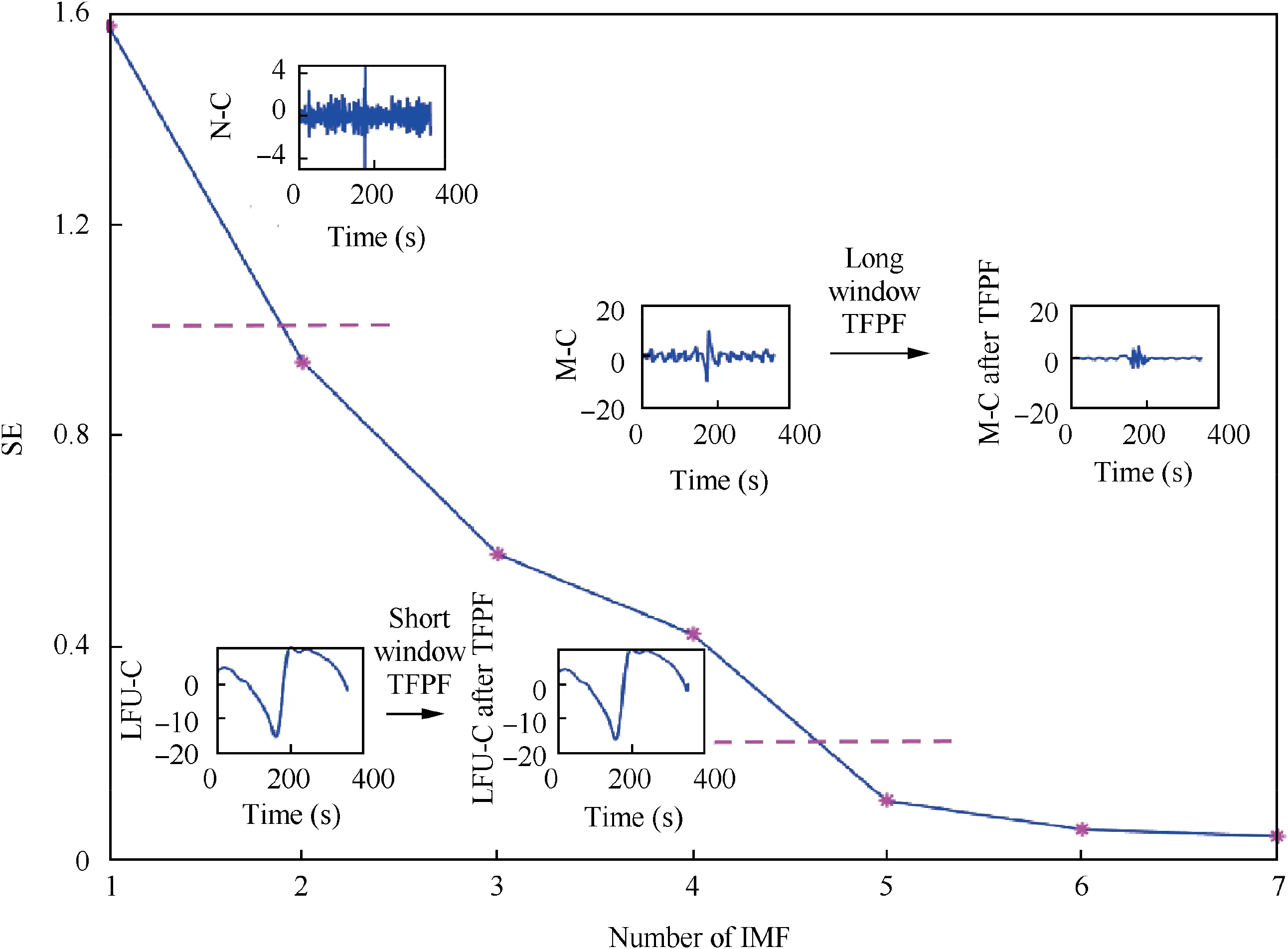
Fig. 9 Classified IMFs and denoising procedure of MS-TFPF for obtaining rotational signal.

Table 10 Complete parameter settings of MS-TFPF.
4.3.2. Static experimental and comparison
To verify the effectiveness of the proposed MS-TFPF furtherly, another set of heading angle and error signal were obtained by a static experiment as the polarized light compass installed on the three-axis turntable was maintained stationary so as to guarantee that the output signal of the polarized light compass was not affected by any movement. The MS-TFPF denoised results of the heading angle together with heading error results and the comparison with other data denoising methods are shown in Fig. 11(a) and (b). It can be observed that there is an outstanding heading error decreasing trend by the long-window TFPF used for the H-C and shortwindow TFPF for LFT-C.
In addition,Table 12 lists the mean,SD,and RMSE of the static signal of each data denoising algorithm. Both the SD and RMSE of the proposed MS-TFPF algorithm are the minimum at 0.1222, which further manifests that the MS-TFPF algorithm performs best among current denoising methods in terms of decreasing heading angle error.
4.3.3. UAV flight experiment results and comparison
The final experiment conducted to verify the effectiveness of the proposed MS-TFPF was UAV flight test around the Engineering Training Center building in NUC, in which the heading angle and heading error data were collected with the polarized light compass (as described in Section 4.1) equipped on UAV. The UAV flied at a height of 300 m to the ground and the flight trajectory was shown in Fig. 12.
The UAV heading angle experimental results and the comparison between the MS-TFPF and other different data denoising methods are displayed in Fig.13(a)and(b).Clearly,the heading error is reduced sharply by the proposed MSTFPF data denoising method although several spikes in Fig. 13(a) and (b) are caused by turning and shaking during flight, indicating that the proposed algorithm has an excellent performance on improving the accuracy of UAV navigation by the adaptive TFPF threshold selection method introduced in Section 3.2 after decomposing the output heading angle data into seven mean IMFs.It can also be clearly seen that the spike noise occurred in direction changed process is also first distinguished by EEMD and then reduced effectively by the TFPF algorithm.
Table 13 elucidates the mean,SD,and RMSE of each data denoising algorithm by UAV flight test after image denoising.The SD and RMSE of the proposed MS-TFPF algorithm are the minimum values of 0.3118 and 0.3116, suggesting that the MS-TFPF performs better than common denoising methods in reducing heading error.
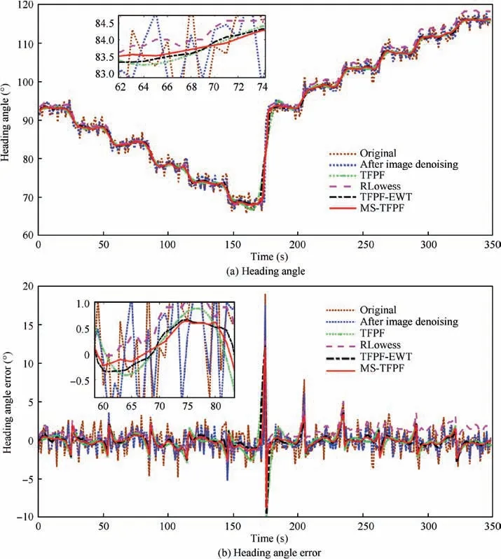
Fig. 10 Heading angle and heading angle error contrast results of rotation signal by using various denoising algorithms.

Table 11 Mean, SD, and RMSE of denoised error of rotation signal.
Consequently, the different experiments verify that the heading accuracy of a polarized light compass for UAV can be improved effectively by the proposed MS-PCA image denoising algorithm and MS-TFPF data denoising algorithm.Moreover, it can be seen the dynamic properties of the MTSbased denoising approach also perform the best superiority compared to other denoising methods from the rotational experiment result in Fig. 10 and real UAV flight test result in Fig. 13. Mean, SD, and RMSE of the heading error of the proposed approach,especially in turntable and UAV turning process,are the smallest from Tables 11 and 13,which further prove the excellent dynamic properties of the MTS-based denoising approach.
4.4. Computation time and complexity analysis of MST-based denoising methods
In order to verify the performance of the proposed MTS-based denoising method more effectively, the computation time and complexity analysis of the proposed methods are given for both MS-PCA image denoising algorithm and MS-TFPF data denoising algorithm.
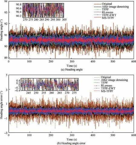
Fig. 11 Heading angle and heading angle error contrast results of static signal by using various denoising algorithms.
4.4.1. Computation time and complexity analysis of MS-PCA
To provide a comprehensive assessment of the proposed MSPCA, the algorithm is subjected to an analysis of computation time and space complexity. To simplify the analysis,we assume the time spent for all operators is the same and the computation complexity concerns only performance and running hardware. In regard to the complexity calculation,the operators involved all require estimating. Hence, we set up addition (ADD), subtraction (SUB), multiplication(MUL), definition (DEF), comparison (CMP) and division(DIV).

Table 12 Mean, SD, and RMSE of denoised error of static signal.
We define S as the length of the input signal. K stands for the number of components decomposed and N stands for the maximum of loops and iterations. In the proposed MS-PCA algorithm, it is developed based on envelope analysis and a sifting process. From the detailed computation, the time and space complexity corresponding to every procedure are listed in Table 14. The MS-PCA time and space complexity are of polynomial order O(N) and linear order O(N), respectively.

Fig. 12 Flight trajectory of UAV.
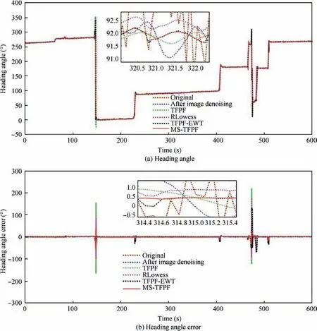
Fig. 13 Heading angle and heading angle errorcontrast results of UAV signal by using various denoising algorithms.

4.4.2. Computation time and complexity analysis of MS-TFPF Similar to Section 4.4.1,the computation time and complexity analysis of MS-TFPF is given as follows. The analysis resultsin Table 15 demonstrate that the proposed MS-TFPF algorithm is also a valid algorithm with solvable in polynomial time for data denoising.

Table 13 Mean, SD, and RMSE of denoised error of UAV signal.

Table 14 Evaluating time and space complexity for MS-PCA image denoising algorithm.

Table 15 Evaluating time and space complexity for MS-TFPF data denoising algorithm.
5. Conclusions
In this study, to improve the accuracy of the unmanned aerial vehicle navigation and reduce the heading error for a polarized light compass, a novel multiscale transform denoising approach is proposed for the first time, which is interested in not only a multiscale principle component analysis denoising algorithm that is directly applied to eliminate the noise in angle of the polarization images but also a multiscale time-frequency peak filtering data denoising algorithm of heading angle data computed from the denoised angle of the polarization images.Moreover, a comprehensive analysis of the polarized light compass noise components is investigated. Static, rotation,and unmanned aerial vehicle flight experiments were conducted to verify the effectiveness of the proposed multiscale transform-based comprehensive denoising method.The experimental results indicate that the multiscale transform denoising method can effectively improve the accuracy of unmanned aerial vehicle navigation by suppressing image and data noise of the polarized light compass compared to existing prior arts.Consequently, the proposed multiscale transform denoising method can be used in real application when the proposed angle of the polarization image denoising algorithm and data denoising algorithm are transplanted into the polarized light compass with the development of hardware technology in future.
The authors declare that they have no known competing financial interests or personal relationships that could have appeared to influence the work reported in this paper.
s
This study was co-supported by the National Natural Science Foundation of China (No. 61973281), and The Innovative Research Group Project of National Natural Science Foundation of China(No.51821003),the Aeronautical Science Foundation of China(No.2018ZCU0002),the Program for the Top Young Academic Leaders of Higher Learning Institutions of Shanxi, Shanxi Postgraduate Innovation Project, China (No.2020BY102), the Young Academic Leaders Foundation in North University of China, the Fund for Shanxi ‘‘1331 Project” Key Subjects Construction.
