Unsteady characteristic research on aerodynamic interaction of slotted wingtip in flapping kinematics
Dn LIU, Bifeng SONG,b,*, Wenqing YANG,c, Dong XUE,b, Xinyu LANG
a School of Aeronautics, Northwestern Polytechnical University, Xi’an 710072, China
b Yangtze River Delta Research Institute, Northwestern Polytechnical University, Taicang 215400, China
c Research & Development Institute of Northwestern Polytechnical University in Shenzhen, Shenzhen 518057, China
KEYWORDS Aerodynamic interaction;Aerodynamic mechanism;Flapping;Unsteady behavior;Wingtip slots
Abstract The slotted wingtip structure of birds is considered to be the product of improving flight efficiency in the process of evolution. It can change the vortex structure of wingtip and improve aerodynamic efficiency. This paper reports a numerical investigation of slotted wing configuration undergoing bio-inspired flapping kinematics (consisting of plunging and in-line movement)extracted from a free-flying bald eagle wing. The aim is to eluci-date the collective mechanism of the flow generated by slotted tips and the lift contribution of each tip. Specifi-cally, the objective of the study is to determine how changes in the wing spacing affect the resulting aerodynamic interaction between the slotted tips and how that affects the force generation and efficiency.Changes in the phase angle between the flapping motions of slotted tips, as well as the spacings among them,can affect the resulting vortex inter-actions. The rear tips often operates in the wake of the frontal tips and,meanwhile,the vortex generated by the movement of the rear tips promote the frontal tips.The interaction of vortices in time and space leads to wing-wing interference and the flow around slotted tips becomes complicated and unstable. The innovative study of wingtip slot in unsteady state leads us to find that the aerodynamic interaction among slotted tips makes the overall lift characteristic better than that of the unslotted wings.The slotted wing configuration can efficiently convert more energy into lift.As the flapping frequency increases,the collective feature of slotted wing with constantly changing gaps can be more advantageous to enhance lift-generation performance.©2021 Chinese Society of Aeronautics and Astronautics.Production and hosting by Elsevier Ltd.This is an open access article under the CC BY-NC-ND license(http://creativecommons.org/licenses/by-nc-nd/4.0/).
1. Introduction
In a long-term natural evolution, birds have gradually formed wing shape and bone structure suitable for efficient flight,they can appropriately change wing shape and flapping pattern in a variety of complex ways to achieve mission adaptability during flight.While some of these capabilities are still not available for current Micro Air Vehicles (MAVs), flying in gusty and turbulent conditions is difficult for them, most of which can only fly in sunny weather.Mohamed et al.evaluated various factors that prevent MAVs from obtaining stable flight characteristics, including low mass, power limitations, low-speed flight, and low Reynolds number conditions. Low Reynolds number may be the most significant obstacle to overcome.At low Reynolds number, wing performance decreases: lift coefficient decreases and drag coefficient increases. In terms of comparing aerodynamic efficiency of traditional wings with bird wings, Withersproved that their performance is similar at low Reynolds number, however, the maneuverability of birds is better than that of MAVs, especially at high angles of attack.That’s to say,we can get inspiration from bird wings to improve MAVs’ behavior instead of airfoil optimization.
In the 1970s,biologists began to study the wing structure of birds. Most birds have prominent and separated feathers at wingtips called wingtip slots, as depicted in Fig. 1.Slotted wingtips are considered as the product of improving flight performance during the evolution of birds.
The purpose and function of the slotted wingtips are an issue of continuous interest. They are considered as a means to yield various improvements, like a drag reduction, lift increase, stall prevention, or increased aeroelastic properties.8Among them, Withersproposed that wingtips had evolved due to improving biomechanical limitations to the bending strength and reducing the propensity for wingtip stall.Tukerexperimented on a Harris hawk glided freely inside a wind tunnel with clipped and unclipped wingtips.It was found that the bird with slotted (unclipped) wingtips had a drag reduction of about 70%-90% in contrast to the clipped one.Saiteja and Sureshinvestigated the aerodynamic performance of two wings:one with wingtip slots and the other without. The results demonstrated that there was a decrease in lift coefficient and an increase in the lift-to-drag ratio for the slotted wing as to compare with a base wing. Kleinherenbrink et al.utilized Particle Image Velocimetry (PIV) to measures the airflow and wake around wingtips of a jackdaw flying unconstrained in a wind tunnel.They proposed the hypothesis that slotted wings originally evolved to enhance the performance of powered flight.
Some scholars also paid attention to the parametric study of wingtip slots, Hossain et al.confirmed that increasing dihedral of slotted winglets can obtain lift raise and drag reduction. Sachs and Moelyadianalyzed the application of swept wingtip in the slotted wing. They demonstrated that wingtip slots with sweep yield a stabilizing yawing moment of significant magnitude and substantially increasing with the lift coefficient. Smith et al.found that slotted wing with appropriate dihedral and twist angle can enhance wing lift and lift-to-drag ratio. Fluck and Crawfordcreated an extended lifting line model to calculate the lift distribution and drag of wings varying with dihedral, tip twist angle, and number of wingtip slots.It followed that wing stall can be alleviated by increasing the twist angle of slotted wingtips. Siddiqui et al.evaluated how dihedral and flexibility impact slotted wings’ behavior. The results revealed that a rigid wing with curved tip had optimum aerodynamic characteristics,and flexibility has a positive impact on drag reduction and stall delay. Lynch et alconducted wind tunnel experiments on wings with plenty of wingtip arrangements.For a planar wing with slot width of 20%, the mean coefficient of lift in the prestall region was increased by 7.25%, and the maximum coefficient of the lift was increased by 5.6%compared to a configuration without tip slots.
The above-mentioned studies provide strong evidence that slotted wingtips or spread feathers improve the efficiency both for bird wings and aircraft.However,the research on the influence of wingtip slots under unsteady conditions is basically blank. Birds are able to produce outstanding agility and maneuverability by generating lift and propulsive force through the unsteady flapping of their wings.Remarkably,the relative positions of multiple winglets formed by the existence of wingtip slots are changing throughout the stroke cycle, forming dynamically varying gaps. Whether the unsteady effect of wingtip slots with flapping has any influence on the improvement of wings’ aerodynamic performance remains unclear.
Motivated by the varying wingtip configuration due to constantly changing gaps among multiple feathers in avian flight,this study numerically investigates the aerodynamic interaction of multiple airfoils arranged like individual feathers.We adopt unsteady kinematics to analyze the flow structure and its correlation with force generation for a collection of airfoils. The core issue is to identify how lift-generation is affected by aerodynamic interaction among the airfoils and why wingtip slots benefit flapping flight of birds, in contrast to single airfoil regarded as the unslotted wing.
2. Models and methods
2.1. Avian winglets kinematics

Fig. 1 Wingtip slots of birds.8
From videos of a level-flying bald eagle taken by a camera viewing the eagle broadside,we are able to recover approximately a time sequence of the slotted wingtip in a whole flapping period.The emphasis should be pressed on the kinematics of the separated primary feathers at the distal end of the wing.The individual feathers in the slotted tips resemble the winglets used on the wingtips of some aircraft. Fig. 2shows a typical image of a flapping eagle viewed from the side and a coordinate system used to describe the kinematics. The leading edge point of the root for the flapping wing is selected as the reference point. Primary feathers that form wingtip slots in images are five points tagged in different colors. The motion of the wrist joint point is also tagged to obtain the kinematic of the unslotted wings. The kinematics of the winglets of a flapping wing can be reasonably described by a first-order Fourier series as a function of the nondimensional time ωt(where ω is the circular frequency of flapping):

where F(t)represents the instantaneous displacements in the x direction(x(t))and the y direction(y(t))at time t,respectively.A, a and b are the corresponding coefficients given by the Fourier series. f is the stroke frequency and T is the period.Therefore, the displacements of the feathers are timedependent functions in a flapping cycle. The maximum value of y is achieved roughly at the moment when a flapping wing is at the onset of the downstroke. Then we assume that ωt=0 corresponds to the position of a wing at the beginning of the downstroke (or the end of the upstroke). Fig. 2 shows the wing position at ωt=0. A time sequence of images of a flying bald eagle taken by a camera from the side view (acquired from hellorf.com) is processed. The displacements of primary feathers in seven consecutive flapping cycles are obtained by manually tracing the corresponding points in digitized images obtained by VoTT software.VoTT is an annotation tool for image target detection released by Microsoft.It is developed based on JavaScript and supports reading annotations from images and videos. Eq. (1) is used to fit data of the successive cycles. After processing and normalizing the data according to the true size of the birds’ wing, the fitting time courses of typical horizontal and vertical wingtip movements are shown in Fig. 3. The left column, from top to bottom, represents the transverse motion of Tip 1, Tip 2, Tip 3,Tip 4, and Tip 5, also known as in-line motion; the right column is their longitudinal movement trajectory (plunging motion).
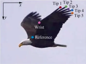
Fig. 2 Level-flying bird (bald eagle) viewed by camera broadside, concerned points are marked with different colors.20
For the flapping eagle wing, the coefficients in Eq. (1) for each slotted tip are listed in Table 1. The fitting error is expressed by R-square (multiple determination coefficient),and its value is between 0 and 1. The closer R-square is to 1,it indicates that the fitted equation variables are closer to the marked points. The results in Table 1 show that for all horizontal displacements x, the values of R-square are around 0.97, and for all vertical displacements y, the values of Rsquare are around 0.99. The flapping frequency is 0.57 Hz,and the period is 1.7453 s. These results will be used to reconstruct the wing kinematics of slotted wingtip. All coefficients for Aare used to determine the initial horizontal and vertical spacings of slotted wing layout at the initial instant ωt=0.The specific values are also listed in Table 2,which will be used to build geometric meshes for our numerical simulation. A schematic drawing of the present slotted wing layout for several varying instants is displayed in Fig. 4. Five slotted tips are subjected to their own flapping motion that consists of plunging and in-line components in a parallel free stream. In the slotted wing configuration, the relative position between tip feathers is constantly changing over time, generally reaching the closest position at the offset of downstroke (or the onset of the upstroke). The images from avaliable video are used because high-speed images of large birds flying in a controllable environment such as a wind tunnel are not available.Thus, it is assumed that the birds observed in nature were in cruising flight in which the cruising speed (V=8 m/s) can be estimated based on the scaling laws in terms of the weight.
2.2. Performance parameters
In this study, two-dimensional simulations are considered to replace three-dimensional simulations because they are verified to provide valuable insight into the unsteady fluid physics related to the flapping kinematics for the slotted wing.The aerodynamic behavior can be measured in terms of aerodynamic force generation and corresponding energy expenditure.These properties are assessed through dimensionless coefficients. The dimensionless lift and drag coefficients can be defined as:

where L and D are the aerodynamic lift and drag forces,respectively. Uis the free stream flow speed, c is the chord length of the airfoil, ρ denotes the density of the fluid.
The aerodynamic power (P) consumed by the wing, which means the energy required to drive the airfoil movement, is calculated as:

Dimensionless power coefficient can be written as:
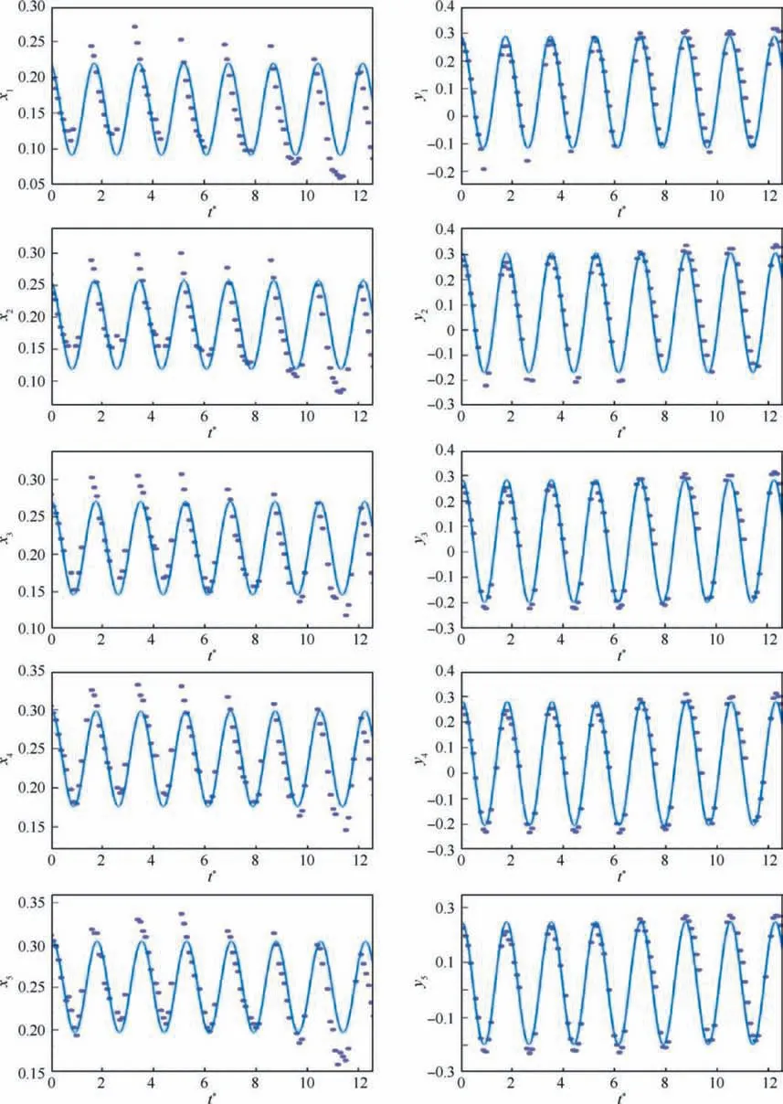
Fig. 3 Normalized time course of horizontal and vertical displacement for slotted tips as function of time.

Then, time-averaged coefficient over one flapping period can be expressed as:


Table 1 Coefficients of kinematic function for slotted tips.

Table 2 Initial horizontal and vertical spacings of slotted wing layout.

Fig. 4 Schematic drawing showing the present slotted wing problem.
where T is the flapping period.
We now examine the time-averaged lift characteristic of the collection of airfoils for slotted wing. The total lift coefficient Cof the slotted wing is defined by:

where Land cdenote the lift force and chord length of the ith tip feather, respectively. Because all airfoils have the same chord length c, Cis simply equal to:

The efficiency of lift can be written as:

The reduced frequency k is the non-dimensional flapping frequency and is defined as:

2.3. Mesh generation and simulations
We now proceed to present our numerical simulation set-up.Using the moving grid approach, four cases were calculated to evaluate the aerodynamic performance of slotted wing, single wing,unslotted base wing,and unslotted flat plate(The single wing with the same chord length (c=0.024 m) is used to compare the aerodynamic effect of the wing-wing interaction among slotted tips; the unslotted base wing and flat plate(c=0.12 m) are used to discuss the aerodynamic characteristic of the slotted wing as a whole).The effects of different flapping frequencies are also studied. Namely, twelve cases in total.The inner O-type computational domain of slotted wing configuration is illustrated in Fig.5(a),each tip has a curvilinear grid within a background Cartesian grid. Parts of the two tip-grids overlap when the two tips move close to each other.The tip grids, as shown in Fig. 5(b), capture features such as boundary layers, separated vortices and vortex/airfoil interactions,etc.The background grid surrounds the airfoil grids and carries the solution to the far field(Fig.5(c)).Mesh systems of these cases are similar. The turbulence model and numerical algorithm are the same as those used in the solver validation,which will be described in detail in Section 2.4. All cases were calculated for 6 cycles and the results of the last cycles are analyzed.
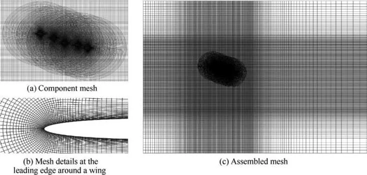
Fig. 5 Overset mesh system in slotted tips simulation.
2.4. Numerical method
Computational simulations are performed by ANSYS FLUENT software, which solves the 2D unsteady, incompressible Navier-Stokes equations based on a finite volume method, to examine the aerodynamic features of slotted wings and to visualize the flow distribution over wings. The accuracy of this package has been extensively validated against several experimental and numerical studies in flapping wing aerodynamics.The flapping motion of wings leads to a moving boundary problem. A moving grid approach is needed to dynamically update the computational grid to accommodate the wing motion, and thus an overlapping moving grid method is adopted. This method enables the use of boundary conforming structured grids to achieve high-quality representation of the boundaries associated with the airfoil surface while still allowing the use of Cartesian grids to represent the flow field so that the efficiency inherent to such grids can be exploited. In the overlapping grid method, interpolation points are located in the overlapping region between different grids and are used to couple the solutions. As the body moves, the grid associated with the body moves with it, meaning that only the interpolation points between overlapping grids should be recalculated as opposed to the need to regenerate the whole mesh. The overset mesh, consisting of background mesh and component mesh, is considered to be suitable for the large-scale motion simulation. During the dynamic movement, the background mesh stays stationary, while the entire component mesh moves as a rigid body with the airfoil controlled by a User Defined Function (UDF). Consequently, the component mesh can keep high mesh quality during its movement.
The k-ω SST turbulence model was chosen for this Computational Fluid Dynamics (CFD) study and implemented to capture turbulent flow around wingtips. The k-ω SST model can be used as a low-Reynolds flow application without extra damping functions. SST stands for Shear Stress Transport,which helps overcome the common problem with the k-ω model that it is too sensitive to free stream turbulence conditions at the inlet. The k-ω SST model also accounts for its good behavior in adverse pressure gradients and separated flow.Several important solver settings are highlighted as follows.Momentum,turbulent kinematic energy,and specific dissipation rate are discretized with a second-order upwind scheme.Second-order accuracy is applied to calculate the pressure. The coupled algorithm is employed for the pressure-velocity coupling, and temporal discretization was performed using a first-order implicit formulation. Temporal subiterations with multigrid are employed to reduce the linearization and factorization errors.
For the simulations, a rectangular fluid domain of [-34c,61c]×[-38c, 32c] is constructed (Fig. 6(a)), where x and y are the streamwise and cross-flow coordinates. The origin of the fluid domain is located at the center of the third airfoil(Tip 3). Symmetrical airfoil NACA0006 (chord length c=0.024 m) is selected for our study object. The inner zone is a circle with a radius of 6c.Fig.6(b)illustrates the schematic diagram of the inner computational domain for the slotted wing, which is further sub-divided into five smaller ‘‘dynamic zone”. The specific values of transverse and longitudinal gaps for the initial slotted wing layout have been given in Table 2.Because the aspect ratio of a typical feather of a bird is large and ranges between 5 and 10, the two-dimensional model is appropriate to find the salient features of multi-feather interactions first before proceeding to a more complex threedimensional model. From left to right in Fig. 6(b), the airfoils are termed Tip 1, Tip 2,Tip 3, Tip 4,and Tip 5;the collective airfoils for all together.The unslotted base wing and flat plate case are also considered for comparison:in these cases,a single airfoil or flat plate with five times chord length (5c=0.12 m)of one feather is placed alone in the fluid domain (Additionally, the flat plate for control is the same thickness as one feather.). Five tips, together with the horizontal and vertical gaps among them, are scaled according to their actual size,as introduced in Section 2.1. The far-field inlet of the domain has a velocity-inlet boundary condition with the magnitude of the velocity component in x-direction prescribed. The far-field outlet is a pressure-outlet with zero gauge pressure. Furthermore, the airfoil has a no-slip wall boundary condition.
2.5. Validation and verification
To validate our computational set-up,we compare the numerical results against experimentaland numerical datain references. The experimental was conducted by Lee and Gerontakoson NACA0012 airfoil with pure pitching motion around c/4 at Re=1.35×10. The angle of attack of this pitching airfoil is a sinusoidal function described as follows:

In this case, the pitch-bias angle is set to 10 degrees. The pitching amplitude is set to 15 degrees, which means the angle of attack ranges from-5 to 25 degrees.The free stream velocity is 14 m/s, and the reduced frequency in this case k is 0.1.Detailed descriptions are documented in Lee and Gerontakos.
The topology of the mesh and computational domain we constructed for validation is similar to the previous one introduced in Section 2.3. The total number of the cells for the assembled mesh is around 1.3×10. Four kinds of time steps were used for time step refinement, which was 1000, 2000,3000, 4000 per cycle. All cases were calculated for 6 cycles and the results of the last cycles are analyzed.
Fig.7 shows the comparison between the present numerical results and the experimental results of Leeand the numerical results of Li et al.It can be found that when the time step is less than T/3000, the overall trends of them are consistent,except for some differences in detail.The discrepancy between present simulations with the experimental results mainly appears in the downstroke phase, particularly when the angle of attack is greater than about 20 degrees. During the deepstall phase,the formation and shedding of leading and trailing edge vortex appear alternately, leading to an obvious fluctuation and inaccurate calculation in the lift coefficient, and this phenomenon is common in the calculation results from different studies. There is deep flow separation accompanied by complex vortices at the post-stall stage, which may lead to inaccurate calculation. The numerical simulation may also be affected by many factors like grid quality and turbulent model,which have been discussed in previous numerical studies.Besides, in the wind tunnel experiment, measuring the surface pressure is also difficult because of complex flow structures in the deep stall case, which may lead to inaccuracies for experimental data.Therefore, the difference between the present calculation and experimental results is reasonable.
Overall, the present results show good agreement in trend with the experimental data when the time step is less than T/3000. Thus, considering the calculation accuracy and time cost, the current time step T/3000 will be adopted for subsequent simulations.
A grid sensitivity analysis was performed to determine the grid resolution necessary to provide accurate force data as well as to resolve the flow field around the airfoils. The same kinematics are used for the sensitivity analysis as were presented in Section 2.1. In view of the complicated and special grid topology of the slotted tips utilized in this paper, its grid independence is firstly verified. The geometric topology of the internal dynamic zone is depicted schematically in Fig. 6(b).In the study,we systematically tested the effect of domain size and grid resolution of each individual overlapping grid, but here we only report the results from different airfoil grid resolutions. Coarse,medium, and fine airfoil grid resolutions were tested respectively with 79920, 160089, and 3236865 grid amount, detail information is listed in Table 3.
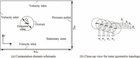
Fig. 6 Computation domain schematic and close-up view for inner geometric topology of overset mesh (initial horizontal and vertical spacings of slotted wing layout at ωt=0 are termed as h1, h2, h3, h4 and w1, w2, w3, w4).
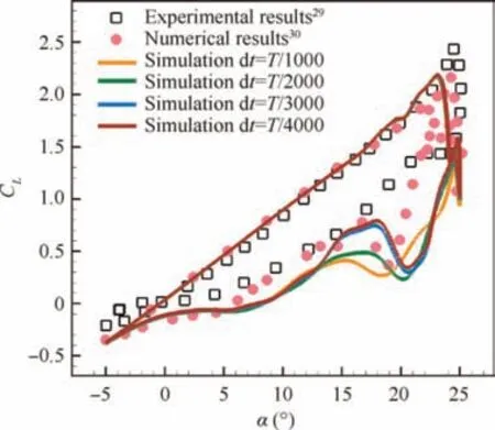
Fig.7 Comparison of present numerical results with experimental results from Lee29 and other numerical results from Li.30
Fig.8 shows the lift and drag coefficients over a single flapping cycle for different grid resolutions.For the slotted wing as a whole,changing the grid resolution did not have a significant effect on the force data, with a small deviation between drag extreme values for coarse and medium grids.More specifically,the lift curves in the three cases coincide throughout the flapping cycle; the drag curves of the medium grid and fine grid are nearly identical. Since there was very little difference in the force data between the results from the medium grid and the fine grid. For the consideration of calculation accuracy and time cost, it was decided to adopt the medium grid type for slotted wing analysis. Based on the above Validation and verification, we have ensured that the current computational set-up is reliable.

Table 3 Grid resolution used in grid sensitivity analysis.
3. Results and discussion
In this section,the aerodynamic influence of wingtip slots for a flapping wing is analyzed in detail. In the flapping motion of avian flight,the unsteady transient effect is of great importance in understanding the overall lift generation.For our model,we limit our interest to the lift characteristic and its potential aerodynamic mechanism. For the slotted wing, each tip moves independently, and their kinematic equations are described in Section 2.1. To explain why slotted wing configuration can enhance lift, the lift histories during one cycle, vorticity, pressure, wake interaction, effective angle of attack, and effective velocity for the slotted wing, single wing, unslotted base wing,and unslotted flat plate are evaluated.After that,the impact of flapping frequency on aerodynamic performance for these situations was also studied.
3.1. Transient force
The forces generated in the sixth stroke are demonstrated in Fig.9.For slotted tip feathers work as single winglets,we first compare the lift performance of these wings with that of a single wing with the same chord length solely placed in a uniform flow (Fig. 9(a)). Interestingly, the peak lift of the slotted tip feathers is enhanced as compared with that of the single wing case,as a result of the interaction of the slotted tips.The wake of the tips interferes with each other,and the vortex formed at the last moment will continue to affect the flow field before it leaves. At the start of the downstroke, there are some differences in the lift produced by these tips. Note that these differences nearly vanish at the onset of upstroke for each flapping cycle, since by the start of the upstroke, the dynamics of the wake have reached a limit cycle. The results show that the lift peak values of the five tips differ and gradually reduced from Tip 1 to Tip 5 in the downstroke.This aerodynamic interaction promotes the first three tips, their lift peak values are larger than that of the single wing. The lift histories of the five tips in the upstroke are less differentiating at some level except for Tip 5. The legend in the upper right corner summarizes time-averaged lift coefficients over a single flapping period for each tip, together with a single wing configuration. Due to the larger negative lift value produced on Tip 4 during the course of the upstroke, its time-averaged lift coefficients are negative. In general, the slotted tips produce more lift than the single wing.
The time histories of lift during flapping for the base wing,flat plate, and slotted wing regarded as a whole wing are depicted in Fig.9(b).The combined force coefficient represents the total force experienced by a flyer with a slotted wingtip. It can be seen that the lift force has a notable increase when the slotted wing is combined together.The lift courses of unslotted base wing and flat plate almost coincide, and there is a phase difference in the peak lift compared to the slotted wing. The slotted wing can generate larger lift than unslotted wings during nearly 80% of the downstroke, and the time-averaged lift coefficients is substantially greater than unslotted wings. The computational results, hence, evidence that the aerodynamic interaction between the tip feathers has a beneficial effect on the lift performance.
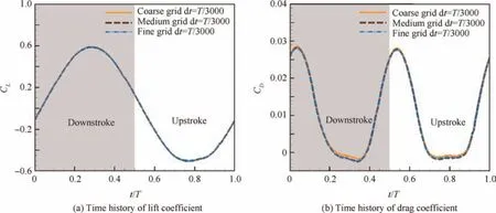
Fig. 8 Time histories of lift coefficient and drag coefficient for slotted wing with different grid resolution.
The time-averaged lift and power coefficients together with lift efficiencies of all flapping models are compared in Table 4.Both of the base wing and flat plate configurations have an exceptionally lower lift efficiency. The slotted wing configuration can produce the largest lift efficiency,which indicates that the input energy is converted into lift more efficiently.In other words,the slotted wing in flapping kinematics is quite economical motion,which could explain the saving energy behavior of birds’ flight to a certain extent.
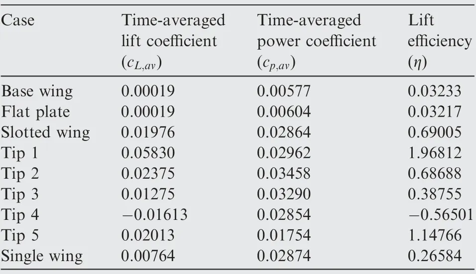
Table 4 Time-averaged lift, power coefficient and lift efficiency for different cases.
3.2. Vorticity contours and streamlines
In order to provide a detailed insight into the wing-wing interaction and explore the aerodynamic mechanism of how wingtip slots can promote lift performance, the instantaneous vorticity contours and streamlines for all flapping configurations are plotted in Figs. 10-12 (where red contours represent positive (counterclockwise) vorticity and blue contours represent negative (clockwise) vorticity). Dimensionless vorticity is scaled by U/c. Several certain moment (t/T=0.21, 0.29,0.50, 0.72, 0.80, 0.92, marked by pink lines in Fig. 9) are selected to provide a quantitative comparison of flow dynamics.
Similar flow topology can be observed in the flapping modes of unslotted base wing and flat plate. The flow around unslotted wings is relatively smooth. However, the boundary layer flow of them varies slightly due to the different thickness.As revealed in Fig. 10, NACA0006 is a thicker airfoil with a rounder nose, but the flat plate has a sharper leading edge.Under the same flapping motion, the rolling up of Leading Edge Vortices(LEV) can be observed in the upstroke and downstroke process of the flat plate, but the base wing does not.
However,in the case of the slotted wing,the formation and shedding of the vortices in a different way. The leading edge vortices can be visibly observed on the first three tips during the upstroke and downstroke. As the slotted tips move downward, the shear layer formed at the leading edge rapidly rolls up into the leading edge vortex on the upper side of the airfoil.With the feeding of the shear layer,the LEV grows in both size and strength and continues to travel downstream. Obviously,LEVs are formed on the upper surface during the downstroke,while they formed on the lower surface during the upstroke.The LEVs formed from slotted tips roll up slower and the strength is weaker along the free stream direction, namely,from Tip 1 to Tip 5.
The interaction with neighboring tips causes each of the tips to encounter a diverted incoming free stream, and so the local effective angle of attack is different from the actual angle of attack for each tip with respect to the free stream. Although the angle of attack the free stream is 0 degrees, the flapping mode with dynamically changing transverse and longitudinal spacings between slotted tips makes the surrounding airflow produce a non-zero relative angle of attack greater than that of unslotted wings. The diversion of the free stream is mainly the result of tips partially blocking the flow between them.When fluid flows around the slotted tips, boundary layers develop on the upper and lower surfaces of each slotted tip.The boundary layers partially block the free stream and change its direction.This diversion of the free stream is clearly demonstrated by the locally enlarged view of the slotted wing in Fig.10(d),Fig.11(d)and Fig.12(d).As a consequence,the effective angle of attack for each tip becomes higher than the actual angle of attack, and thus, greater lift acts on them.
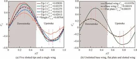
Fig.9 Time histories of lift during one complete stroke cycle(the dimensionless instant marked by the small pink lines will be analyzed in detail subsequently).
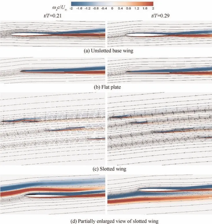
Fig. 10 Instantaneous streamlines and z-vorticity contours for t/T=0.21 and t/T=0.29.
As for the collective behavior of the slotted wing, it is of interest to note that the timing that the LEV separates from the upper surface is different, leading to a discrepancy of the moment that the peak lift force appears both for slotted wing and unslotted wings, just as Fig. 9(b)shows. Figs.10-12 illustrates how dynamically changes in the tip spacings affect the timing of the wing-wing interactions. As the gaps between the slotted tips gradually become larger or smaller with time,the airflow passing through the gap between two adjacent tips is expanded or compressed.The shear layer shedding from the frontal tip continues to develop downstream passing through the rear tips sequentially and form a wake region, which will interact with the shear layer of the rear tips. The direction and magnitude of wake streams generated by slotted tips are different, as depicted in Figs. 10-12. The vortices generated by the plunging and in-line motion of slotted wing at the last moment will also disturb the flow at the later time,which contributes to the vortices in the frontal tips as well,until they flow out of the flow field or dissipate. In other words, the interaction of vortices in time and space leads to wing-wing interference and the flow around slotted tips becomes complicated and unstable. This constructive interaction translates into a much stronger LEV on the frontal tips(Tip 1 and Tip 2).The timing of the vortex interaction has large implications on the LEV generation of the rear tips. Therefore, the performance of the rear tips (Tip 4 and Tip 5) are significantly affected by the shedding vortex of the frontal tips and gradually decrease due to wider wake region, which is clearly observed as amplitude discrepancies in the transient lift data depicted in Fig. 9(a). It can be seen from Fig. 11(c) and Fig.12(c) that the relative position of Tip 5 in the vertical direction is higher in the upstroke. In this scenario, Tip 5 is scarcely affected by the wake from frontal tips, which is revealed in its lower negative lift in Fig. 9(a).
3.3. Pressure contours and pressure coefficients
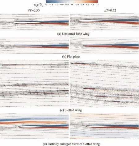
Fig. 11 Instantaneous streamlines and z-vorticity contours for t/T=0.50 and t/T=0.72.

Different vortex structures at these moment (t/T=0.21,0.29,0.50,0.72,0.80,0.92,marked by pink lines in Fig.9)contribute to the discrepancy of lift.The effect of the vortex interaction on the pressure distribution around the wings is depicted in Fig. 14. The chordwise pressure coefficient distributions over base wing, flat plate, and different slotted tips are plotted along a normalized chordwise axis in Fig. 14.(Due to the different positions of each tip in space at that moment, for the convenience of comparison, the leading edge points are merged into the same x coordinate.Hence the x axis in Fig. 14 is omitted.) The y-axis is reversed so that the top of the curve corresponds to the upper surface (negative pressure)and vice versa. During the downstroke (Fig. 14(a) Fig. 14(b)),the pressure difference and lift sequentially declined for the five tips along the streamwise direction.Compared with the unslotted base wing and flat plate, the first four tips have wider region and lower suction force and then a higher lift force.Additionally,the lower pressure difference and smaller vortices on Tip 5 make its lift performance unsatisfactory.The pressure coefficient distribution of unslotted wings is relatively close to that of Tip 5 in numerical value, but the distribution trend is slightly different. At the offset of downstroke (or the onset of the upstroke,Fig.14(c).t/T=0.50),there is little difference in pressure distribution among the five slotted tips, which is shown in Fig.9(a)by a close lift value at this moment.During the upstroke (Fig. 14(d), Fig. 14(e), and Fig. 14(f)), as illustrated in the right column of Fig. 13, Tip 1 is far away from other tips at these moments,so the impact of wing-wing interaction between slotted tips on it becomes weaker,and its pressure distribution area becomes narrow.The overall behavior of pressure confirms our earlier analysis on the flow structure,that is,the aerodynamic interaction between slotted tips is critical to lift generation. Another important conclusion that can be drawn from Fig.14 is that although the pressure difference and vortices of the last two tips in slotted wing configuration are relatively smaller, the interaction between slotted tips makes the overall lift performance better than that of the unslotted wings.
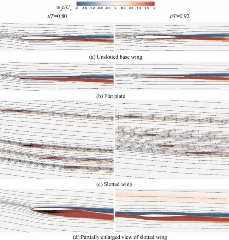
Fig. 12 Instantaneous streamlines and z-vorticity contours for t/T=0.80 and t/T=0.92.
3.4. Velocity contours
The velocity magnitude contours u/Uand v/Uat the instant t/T=0.29(corresponding to the maximum lift of slotted wing) are shown in Fig. 15. The angle of attack as well as the velocity of the incoming free stream is influenced by the aerodynamic interaction of multiple winglets and deviates from that of the single wing; the deviated velocity is termed as effective velocity.This diversion of the free stream is clearly demonstrated by x-directional and y-directional velocity contours in Fig. 15. For the slotted wing, the incoming velocity of each tip reduces between the first and fifth tips due to the partial blocking by the boundary layers. The velocity difference between the upper and lower surfaces at the leading edge lessens in turn,and the wake structures at the trailing edge also have discrepancies, significantly different from the horizontal wake behind the unslotted base wing and flat plate. In Fig.15,the LEV around the first tip is stronger than other tips in the configuration,and the vortex shedding process is clearly observed for Tip 1. This is mainly because of the higher effective angle of attack and effective velocity around Tip 1.Although each tip has a different effective angle of attack and effective velocity,the flow structures of each plate are synchronized with each other, and the tips have the same frequency of vortex shedding and lift fluctuation, albeit with a slight phase difference (seen in Fig. 9(b)).
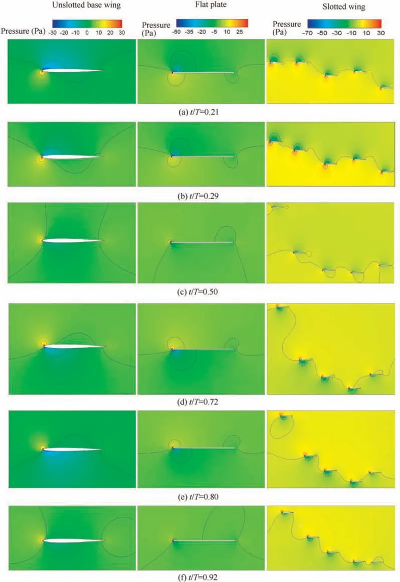
Fig. 13 Instantaneous pressure contours of unslotted base wing, flat plate and slotted wing at some typical instants (marked by pink lines in Fig. 9).
3.5. Effect of flapping frequency
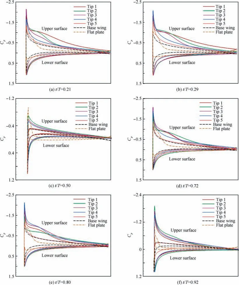
Fig.14 Pressure coefficient distributions of five slotted tips,base wing and flat plate at some typical instants(The leading edge points are merged into the same x coordinate after normalization, so x axis is not shown here).
The flapping frequency as a further critical parameter in flapping motion is considered in the present section.Fig.16 shows the transient lift coefficients in a whole flapping cycle under flapping frequencies f=0.57 Hz, f=1.14 Hz, f=1.71 Hz,and f=2.28 Hz,focusing on the comparison of lift characteristic between the slotted wing and unslotted wings. As observed in Fig. 16, the lift of every mode increases substantially when increasing flapping frequency. Fig. 16(a)-16(c)show similar trends in the lift courses of the unslotted base wing and flat plate, where some slight differences also exist.The slotted wing can obtain higher lift in most of the time of the upstroke and maintain higher lift in a long platform period. Meanwhile, the negative lift valley value slotted wing is close to that of unslotted wings. As a result, the timeaveraged lift coefficient over one flapping period of slotted wing is three orders of magnitude larger than base wing in the cases of f=1.71 Hz and f=2.28 Hz. Note that the maximum achievable lift for unslotted flat plate is comparably equal to slotted wing as demonstrated in Fig. 16(c) and Fig.16(d).However,in terms of slotted wing,the extended lift platform period and smaller negative lift valley value make it still can acquire a considerable advantage in the timeaveraged lift characteristic. As flapping frequency increases excessively (Fig. 16(d)), the interaction among slotted tips exacerbate,and thus,the lift curve fluctuates dramatically during the whole flapping cycle for slotted tips.
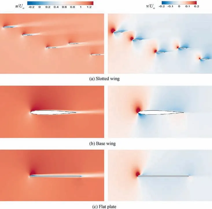
Fig. 15 Instantaneous x-directional and y-directional velocity contours around slotted wing (from left to right are Tip 1, Tip 2, Tip 3,Tip 4,and Tip 5,respectively),base wing,and flat plate at the instant of t/T=0.29(corresponding to the instant when achieving the peak value of lift).
The behavior observed in the lift courses can be explained by analyzing the vorticity contours for each case. Specifically,examining how changes in the flapping frequency change vortex interactions. An increase in flapping frequency allows the flow around slotted tips to interact with each other more active instead of detouring around the tips.More momentum is contained in the interwing flow. From Fig. 17 and Fig. 18, they follow that how flapping frequency or reduced frequency influence the incoming flow passing through the slotted wing and unslotted base wing (as observed in Section 3.2, the vortices around flat plate are similar to that of base wing, so they are not given here). The vorticity contours and streamlines of the slotted wing and base wing for three reduced frequencies at t/T=0.14, 0.40, 0.66, 0.92 (marked by pink lines in Fig.16)are plotted to get an intuitive impression.At the leading edge points of slotted tips, it can be clearly seen that the airflow forms an angle with the chord line of tips. The whole wake formed by slotted tips deflect upward during the downstroke and downward during the upstroke. From left to right in Fig. 17, with the flapping frequency adding, these phenomena become more pronounced. The blocking effect and interference between airflows intensify with flapping frequency,the local effective angle of attack of slotted tips continues to grow with flapping frequency as well.
LEV is often correlated with the angle of attack, and the presence of the frontal tips can alter the incoming flow experienced by the rear tips. For downstroke, the shear layer from the frontal tips induces an upwash on its upstream side,which the rear tips experience after the interaction. As a result, the incoming flow for rear tips seems to be deflected upward compared to the uniform parallel free stream for the unslotted base wing(Fig. 18). This understandably leads to a higher effective angle of attack of the slotted tips and thus a stronger LEV.Conversely, a similar wake interaction occurs during the upstroke, resulting in a larger local negative angle of attack for slotted tips and a downward deflection of the overall airflow. For these specific instants, the rear tip pass through the vortex shed from the frontal tip at nearly the same time,resulting in similar LEV generation on the rear tip. Specifically, the timing of LEV generation and shedding are approximately the same despite the difference in gaps and phase differences.This corresponds to the similar lift courses for the five tips during the flapping cycle. There are slight differences in the size of the LEV,which results in the differences in the peak lift among the slotted tips.
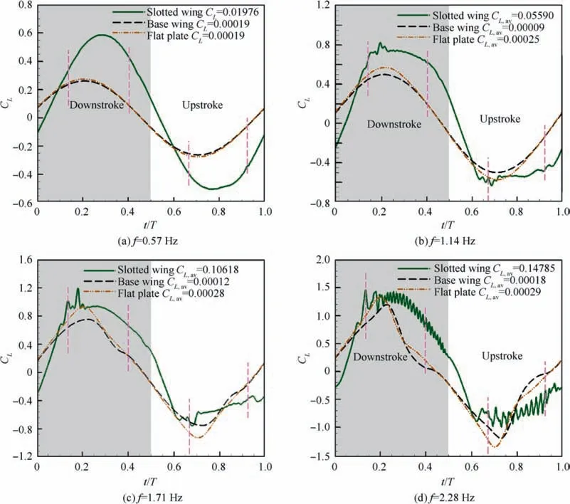
Fig. 16 Time histories of lift during one complete stroke cycle for flapping frequency, the dimensionless instants marked by the small pink lines will be analyzed in detail subsequently.
The enhancement of flapping frequency makes our previous conclusions more conspicuous.Namely,the interaction of vortices in time and space leads to wing-wing interference and the flow around slotted tips becomes complicated and unstable.At closer spacings, the vortex interaction is stronger because the vortex shed from the frontal tip has less time to dissipate before interacting with the rear tip. As the reduced frequency increases, the size and strength of LEVs become larger, then moves to the trailing edge and gradually enclosing the entire layers, finally meeting the trailing edge vortex at the trailing edge and entering the wake together. Affected by the continuous influence of wing interaction,a new round of leading edge vortices begin to roll up from the leading edge (which can be clearly observed on the third tip of Fig. 17(b)). Furthermore,by contrary, the vortices around the unslotted base wing have little variation (Fig. 18). The right column of Fig. 17 and Fig. 18 shows the vorticity contours when the flapping frequency is 2.28 Hz.Vortex cores are also revealed near the surface of the base wing(Fig.18(a)and Fig.18(c)),and the airflow no longer flows smoothly through the wing.In terms of slotted wing,LEVs form and roll up rapidly.Before they gradually dissipate in the flow direction, new LEVs continue to generate.These vortices merge and accumulate. Successive positive and negative vortex pairs can be observed in the wake region of these tips. These wake has a severe and negative impact on the rear tips, which leads to the deterioration of the overall aerodynamic characteristics of the slotted wing.The fluctuation in the transient lift data can be found in Fig.16(d).
Fig. 19 illustrates the y-direction velocity contours of slotted wing and base wing at the instant of t/T=0.66 (marked by pink lines in Fig. 16) under varying flapping frequency,respectively. These velocity contours are typical for slotted wing configuration, there are negative low velocity regions near the leading edge of the lower surface for each tip, and high velocity regions encircle these boundary layers.The highest velocity variance of the incoming flow encountered near Tip 1.As reduced frequency becomes larger,the velocity magnitude of the flow surrounding five tips grows remarkably and the area of high-speed flow expands.The wake gradually deviates from the free stream direction and has a greater impact on the rear tips, which implies that the effective velocity remarkably rises and the direction deviates from the free stream direction.At f=2.28 Hz,low velocity region can be observed near the trailing edge of upper surfaces for Tip 1 and Tip 2.In contrast, for the last three tip (Tip 3 - Tip 5), the combination of the anterior wake causes the vortices around them to become chaotic,and broaden regions suffer high vertical velocity,even the whole surface of Tip 5 is completely surrounded in a highspeed zone.Therefore,the collective lift property of the slotted wing demonstrated in Fig. 16(d) fluctuates and becomes unstable.
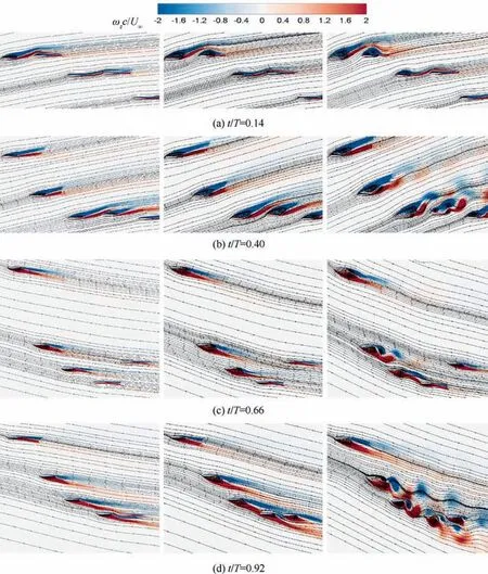
Fig.17 Instantaneous streamlines and z-vorticity contours of slotted wing at the instant for flapping frequency f=1.14 Hz,f=1.71 Hz and f=2.28 Hz (from left to right).
4. Conclusions
Inspired by the dynamically changing gap flow between primary feathers in avian flight,we have investigated the aerodynamic interaction of multiple airfoils arranged like individual feathers of slotted wingtip undergoing bio-inspired motion.We focused on the issue that whether the unsteady effect and wing-wing interaction of wingtip slots have any contribution on the improvement of wings’ aerodynamic characteristics. A numerical investigation had been conducted to clarify the aerodynamics of a flapping slotted wing configuration at a Reynolds number of 66000. The gaps between slotted tips are dynamically varying during the whole flapping period.Detailed comparisons were made with three flapping wings(base wing, flat plate, and slotted wing) in terms of the lift and power coefficients, lift efficiencies, and vorticity, pressure,and velocity contours. Several mechanisms were disclosed for the explanation of the lift enhancement by the wing-wing interaction. The following observations were made:
(1) The slotted wing can generate larger lift than unslotted wings during nearly 80% of the downstroke, and the time-averaged lift coefficients is substantially greater than unslotted wings.The kinematics of the slotted wing is quite economical flapping motion, which could explain the saving energy behavior of birds’ flight to a certain extent.
(2) As the gaps between the slotted tips gradually become larger or smaller with time, the airflow passing through the gap between two adjacent tips is expanded or compressed. The shear layer shedding from the frontal tip continues to develop downstream and interact with the shear layer of the rear tips.The vortices generated at the last moment will also disturb the flow at the later time,which contributes to the vortices in the frontal tips as well.
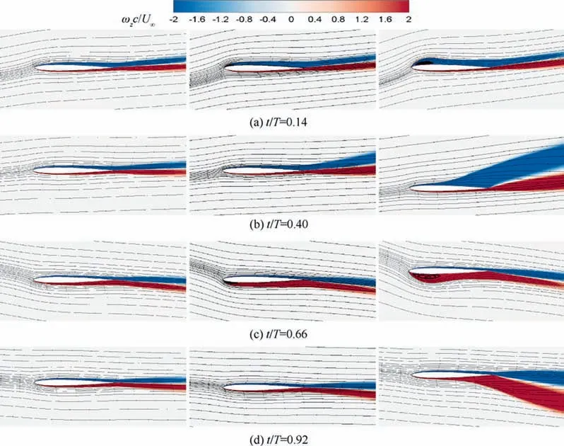
Fig. 18 Instantaneous streamlines and z-vorticity contours of unslotted base wing at the instant for flapping frequency f=1.14 Hz,f=1.71 Hz and f=2.28 Hz(from left to right).

Fig. 19 Instantaneous y-directional velocity contours at the instant of t/T=0.66 (corresponding to the instant when achieving the valley value of lift) for flapping frequency f=1.14 Hz, f=1.71 Hz and f=2.28 Hz (from left to right).
(3) The interaction with neighboring tips causes each of the tips to encounter a diverted incoming free stream,and so the local effective angle of attack is different from the actual angle of attack for each tip with respect to the free stream. Due to partial blocking of the boundary layers,the pressure difference and effective velocity sequentially declined for the five tips along streamwise direction.The velocity of the incoming flow is influenced by the aerodynamic interaction of multiple winglets and deviates from that of the single wing layouts.
(4) An obvious phenomenon is that higher frequency will increase the lift force. The time-averaged lift of the slotted wing and base wing are 0.10618 and 0.00012 at the flapping frequency f=1.71 Hz. The slotted wing demonstrated a substantial lift improvement despite its simple flapping kinematics (no pitching motion introduced). At some point, however, the frequency is too high, the flow will be unstable and the lift curve will fluctuate continuously. In other words, an excessive increase in frequency will also bring some negative impact.
As a first step to unravel the principles of aerodynamics for multiple lift-generating bodies, we have analyzed the flow structure and its correlation with force generation for a collection of slotted tips in two-dimension. The aerodynamic mechanisms of mutual interaction for slotted tips suggested in this study are not based on the two-dimension of the flow and the unique property of low Reynolds number.Thus,we believe that the main findings of this study can be applied to the higher Reynolds number case of a three-dimensional model to some extent although their relative importance may differ and new mechanisms may emerge.
The authors declare that they have no known competing financial interests or personal relationships that could have appeared to influence the work reported in this paper.
s
The authors would like to express their thanks for the support from the National Natural Science Foundation of China(Nos.11872314 and U1613227) and the Key R&D Program in Shaanxi Province of China (No. 2020GY-154).
