Reduced-dimensional MPC controller for direct thrust control
Shuwei PANG, Soheil JAFARI, Theoklis NIKOLAIDIS, Qiuhong LI
a Jiangsu Province Key Laboratory of Aerospace Power System, Nanjing University of Aeronautics and Astronautics,Nanjing 210016, China
b Propulsion Engineering Center,School of Aerospace,Transport and Manufacturing,Cranfield University,Bedford MK43 0AL,UK
KEYWORDS Computation time;Direct thrust control;Gas turbine engine;Model predictive control;Thrust optimization
Abstract With the development of the aircraft gas turbine engine,a control system should be able to achieve effective thrust control to gain better operability.The main contribution of this paper is to develop a novel direct thrust control approach based on an improved model predictive control method through a strategy that reduces the dimension of control sequence.It can not only achieve normal direct thrust control tasks but also maximize the thrust level within the safe operation boundaries. Only the action of switching the objective functions is required to achieve the switch of these two thrust control modes while there is no modification to the control structure. Besides,a shorter control sequence is defined for multivariable control by updating only one control variable at every simulation time instant.Therefore,the time requirement for the solving process of the optimal control sequence is reduced. The proposed controller is implemented to a twin-spool engine.Simulations are conducted in the wide flight envelope, and results show that the average timeconsumption can be reduced up to 65%in comparison with the standard model predictive control,and the thrust can be increased significantly when maximum thrust mode is implemented by using engine limit margins.
1. Introduction
With the development of next generation aircraft gas turbine engines, a more advanced control system is urged to address various control requirements.Normally, the control system for a gas turbine engine is implemented to drive the engine to complete a certain mission, such as providing thrust at a certain level, and to keep the engine operates safely at the same time. Besides, the control system is expected to be more intelligent than what it is at the current stage, which means that it should not only have the capability to complete the normal flight mission but also provides the ability to address the specific demand in some cases, such as to optimize the performance.
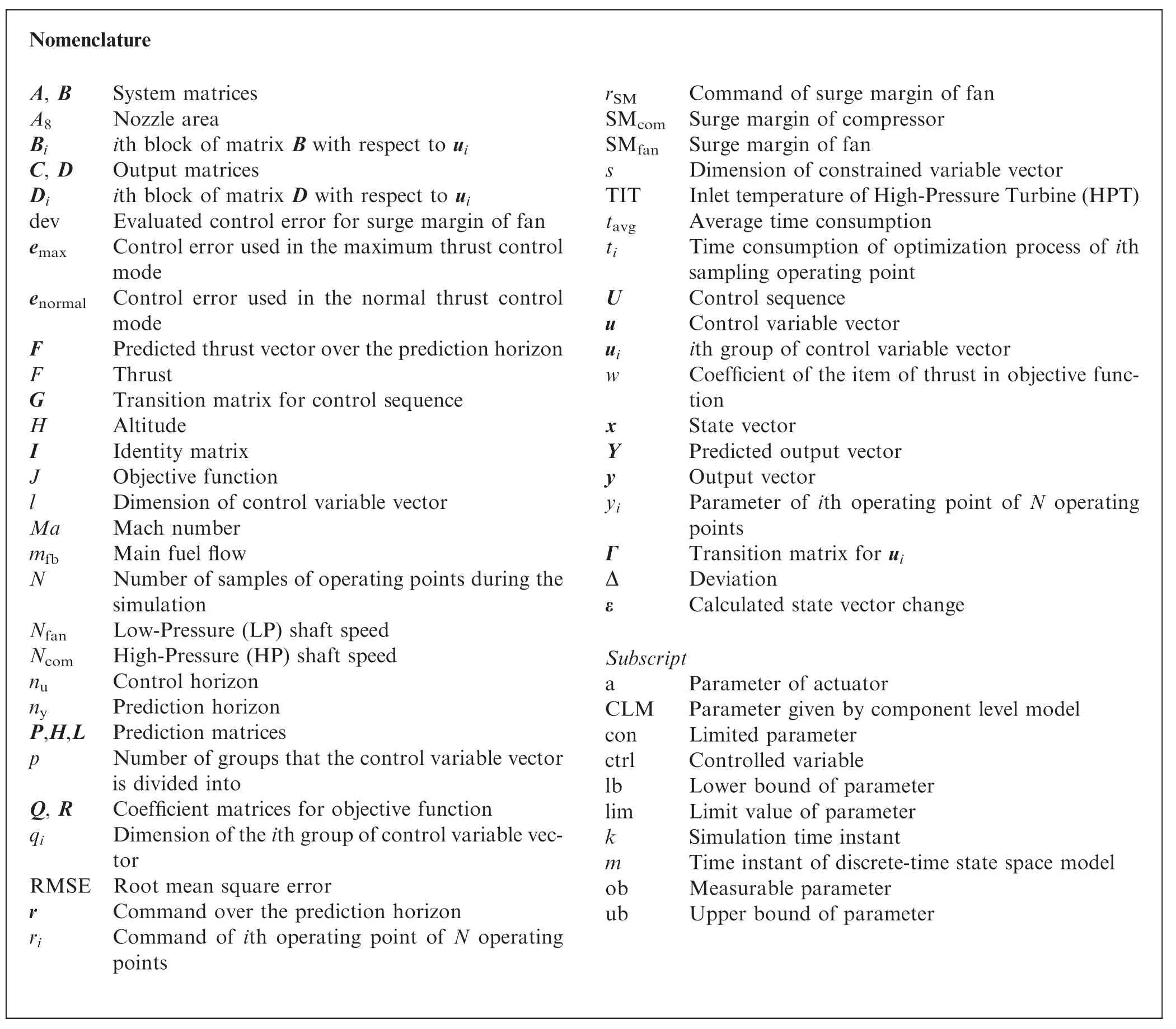
Nomenclature A, B System matrices A8 Nozzle area Bi ith block of matrix B with respect to ui C, D Output matrices Di ith block of matrix D with respect to ui dev Evaluated control error for surge margin of fan emax Control error used in the maximum thrust control mode enormal Control error used in the normal thrust control mode F Predicted thrust vector over the prediction horizon F Thrust G Transition matrix for control sequence H Altitude I Identity matrix J Objective function l Dimension of control variable vector Ma Mach number mfb Main fuel flow N Number of samples of operating points during the simulation Nfan Low-Pressure (LP) shaft speed Ncom High-Pressure (HP) shaft speed nu Control horizon ny Prediction horizon P,H,L Prediction matrices p Number of groups that the control variable vector is divided into Q, R Coefficient matrices for objective function qi Dimension of the ith group of control variable vector RMSE Root mean square error r Command over the prediction horizon ri Command of ith operating point of N operating points rSM Command of surge margin of fan SMcom Surge margin of compressor SMfan Surge margin of fan s Dimension of constrained variable vector TIT Inlet temperature of High-Pressure Turbine(HPT)tavg Average time consumption ti Time consumption of optimization process of ith sampling operating point U Control sequence u Control variable vector ui ith group of control variable vector w Coefficient of the item of thrust in objective function x State vector Y Predicted output vector y Output vector yi Parameter of ith operating point of N operating points Γ Transition matrix for ui Δ Deviation ε Calculated state vector change Subscript a Parameter of actuator CLM Parameter given by component level model con Limited parameter ctrl Controlled variable lb Lower bound of parameter lim Limit value of parameter k Simulation time instant m Time instant of discrete-time state space model ob Measurable parameter ub Upper bound of parameter
As thrust is the most important performance parameter for a gas turbine engine, the concept of direct thrust control is attractive.For conventional control systems,sensor data,such as low-pressure shaft speed, gas exit temperature, and so on,are fed into the control system to achieve the indirect control of thrust since thrust is unmeasurable and these measurable parameters are related to the thrust level.However, these parameters cannot reflect thrust precisely,because there are complicated nonlinear relations between these measurable parameters and thrust.Additionally,the calibration of the relationship between these measurable parameters (e.g. Low-Pressure (LP) shaft speed) and thrust is usually made for the manufactured engine before its entry into service.Unfortunately, this calibration becomes inaccurate when the engine operates and degradations occur. As a result, thrust cannot be controlled to the desired level following the control schedule that is based on the initial calibration.In addition to this, some parameters’ margins must be kept to ensure that the engine can operate safely in the most extreme conditions or when some faults happen unexpectedly, so conservatism is inevitable in the traditional control structure.Thus, more complex controller design methods and control structures are anticipated.Besides that, it is necessary to consider some inevitable factors like random packet loss,dynamic quantization and randomly occurring uncertainties in this sensor-based structure if the control system is networked.Also,the single control loop usually can complete only a control task. Therefore, many control loops for different control tasks should be designed and fine-tuned, and the control loop switch logic needs to be well designed to integrate these control loops to achieve the main control objective and the limit protection function, which raises a series of design challenges of switched systems. This whole process makes the control structure complex.
Therefore,the novel model-based control is attractive at the current stage, which aims at replacing the sensor data with model outputs and feeding these outputs to the control system to control unmeasurable critical parameters directly, such as thrust,the inlet temperature of high-pressure turbine and surge margin.The model predictive control technique is one of the model-based control methods.It has attracted attention because of its capability to handle the main control objective and manage constraints simultaneously in a single controller,which is quite applicable to address control tasks of gas turbine engines.Thus, when a Model Predictive Control(MPC) controller is used, there is no need to design multiple control loops like the traditional structure because functions of different control loops can be integrated into this controller.
In a typical MPC controller, a constrained optimization problem is constructed and solved to get the optimal control sequence at every simulation time instant. However, the solving process of the optimization problem usually raises a high demand for computation recourses. In the currently existing gas turbine engine MPC controllers, the control sequence is defined over the control horizon in the optimization process,but only the elements for current simulation time instant are applied.To the authors’best knowledge,the research attention is mainly paid to the capability of constraint management,model developments, and optimization algorithms rather than the reduction of the computation burden.But the computation burden should be considered because of the limited computational resources of the aero gas turbine engine control system.Thus,it is worthwhile to investigate the reduction of the MPC computation burden when an MPC controller is implemented in a gas turbine engine.A concept called multiplexed method is investigated in Refs. 40,41, but rare further studies are conducted based on these researches for gas turbine engine.
Besides, these researches mainly focus on normal control tasks, namely controlling engine parameters to track control commands generated by a pre-designed control schedule and ensuring that the engine operates within a safe operation boundary. However, an advanced control system should have the capability to complete some specific control tasks.For example, for the take-off period and some emergencies(e.g. one engine inoperative), a larger thrust level may be in demand to ensure the safety of flight and passengers. Thus, a quick increase of thrust exceeding the set-point level is anticipated to provide additional power while the engine operates safely as much as possible. This is normally achieved by increasing the set-point command, constraint relaxation, and control logic switch in a traditional control architecture although these will increase the risk of violating the original limits, which may result in shortening the engine’s life.For this aspect, the MPC controller’s potential has not been investigated in detail, which motivates our work. An MPC controller can optimize some selected parameters during the engine operation because it contains an optimization solver.It means that the controller is able to maximize or minimize some parameters even if there are no explicit commands defining relative operating points,because the optimization process embedded in the MPC controller would find these operating points automatically when a specific objective function is well defined. Thus, it is valuable and practical to develop an MPC based controller that can achieve normal control tasks and specific tasks such as thrust optimization together.
Therefore, an MPC controller for direct thrust control is presented in this article. The main contribution and advantages can be summarized as follow. (A) Compared with existing standard MPC controller applied in aero gas turbine engines,a novel strategy of reducing the dimension of the optimized control sequence is developed.As a result,a much lower computation burden than the standard/conventional MPC algorithm is achieved while no modification of the control structure is required. (B) Based on the feature of MPC controllers, a new objective function is developed to maximize the engine thrust. Thus, the MPC controller’s function is well extended from completing normal direct thrust control tasks to achieving online thrust optimization tasks. Another benefit brought is that both normal direct thrust control and online thrust optimization can be achieved in a single controller by switching the control objective functions without any additional modification of controller structure.
The paper is organized as follows. Section 1 presents the introduction while Section 2 details the proposed control method about direct thrust control.Section 3 discusses the different control modes for direct thrust control and Section 4 analyzes and discusses simulation results. In Section 5, the research conclusions are presented.
2. Control algorithm
2.1. Reduced-dimensional MPC controller description
The proposed MPC controller consists of a predictive model linearized from a nonlinear adaptive model and an optimization solver (as shown in Fig.1), in which the predictive model is used to construct the optimization problem to be solved.
In the proposed method,the controller inputs consist of the commands of controlled variables,the limits of limited parameters, and the limits of actuators. The predictive model is a state-space model that is updated continuously by a nonlinear adaptive model detailed in Refs. 46,47, and then this statespace model is implemented to construct a quadratic optimization problem according to designed objective functions and various constraints. Moreover, because this predictive model is updated every simulation time instant, it provides an approach to reduce the dimension of the control sequence in the proposed method.Besides,two objective functions are presented in the proposed MPC controller to realize different thrust control tasks.Based on the predictive model, the objective functions, and constraints, a constrained quadratic problem can be constructed and solved by the optimization algorithm.
2.2. Predictive model
The predictive model plays an important role in the MPC algorithm,which is used to predict parameter changes over the prediction horizon, and different types of models always determine the computation complexity of an MPC algorithm.For example,a linear model can lead to a quadratic optimization problem when a quadratic performance index is selected,while a nonlinear model always can result in a higher-order nonlinear optimization problem. There is no doubt that it is much easier to solve the former problem than the latter one.
In this paper, a state-space model is used as the predictive model, and this model is linearized from an adaptive Component Level Model (CLM) according to the engine operating state of last simulation time instant k - 1. Thus, this statespace model can be written as follow,and the details about linearization and update for this state-space model can be referred to Refs. 46,47.


Fig. 1 Layout of proposed MPC controller.
Note that the point (x,u) denotes the engine operating point where the state-space model is linearized.
Taking a twin-spool turbofan as an example, the state vector is always comprised of two shaft speeds, namely Low-Pressure (LP) shaft speed Nand High-Pressure (HP) shaft speed N, and the control variables are main fuel flow mand nozzle area Ain this example in this paper.
Because the outputs are divided into controlled variables and constrained variables, the Eq. (1) can be rewritten as

where
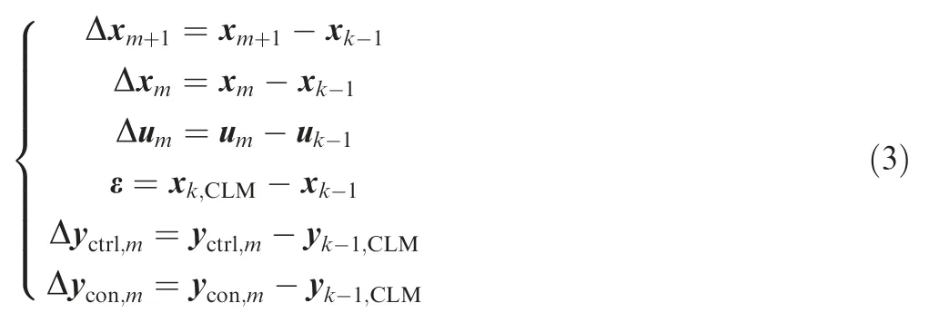
Note that there is a nonlinear item ε that makes the predictive model different from normal state space models. As defined in Eq.(3),it is the change from the state vector of simulation time instant k-1 to the state vector calculated by the component level model for simulation time instant k.This item actually represents the influence of shaft dynamics on the engine operation. When the engine is at steady state, the shaft speeds are unchanged, so ε = x- x= 0. However,when the engine is during the transient operation, the item ε is a non-zero item, which can be considered as the additional increase of shaft speeds caused by the linearization during the transient operation. Thus, the model shown in Eq. (2) is a nonlinear model in fact.
2.3. Reduced-dimensional MPC algorithm
In the standard MPC controller, the control sequence to be optimized is defined as

It can be seen that all the control variables are optimized for every future sampling period over the control horizon.However, only the first vector, namely uis implemented to control the engine. The computation scale of a constrained optimization problem increases as the dimension of the solution increases,so an interesting idea is to reduce the dimension of the control sequence to lower the demand of computation power. Thus, a reduced-dimensional control sequence is defined and optimized in the proposed method.Assuming that the dimension of the control variable vector is l,and the vector is divided into p groups with the dimension of the group q,i = 1,2,...,p. Then, the control sequence can be defined as

It can be seen that the dimension of control sequence defined by Eq. (5) is reduced in comparison with that of control sequence shown in Eq. (4), because every component of the control sequence in Eq. (5) is the ith group of Δu, which means that only a q-dimension input vector is considered over the control horizon every simulation time instant while an ldimension input vector is considered over the control horizon every simulation time instant in Eq. (4). Thus, the dimension of the control sequence in Eq.(5)is nqwhile that of the control sequence is nl in Eq. (4), which is larger than nq. Based on this reduced-dimensional control sequence, a constrained optimization problem with smaller scale can be constructed in comparison with the problem scale that the control sequence in Eq.(4)leads to,which results in a reduction in computation demands.
Another difference is that the elements of Eq. (4) is unchanged except their subscripts of time instant when a new optimization problem is constructed at a new simulation time instant.However,the elements of Eq.(5)are changeable.For example, at simulation time instant k, only the ith group of control variables is implemented over the control horizon in Eq.(5),then it would be only the(i+1)th group of control variables over the control horizon in Eq.(5)at simulation time instant k + 1. What’s more, if the pth group of control variables is considered at time instant k, then the first group of control variables would be implemented in the control sequence at time instant k + 1, and so on. Moreover, there is no need to divide the control vector evenly; instead, some control variables with a strong coupling characteristic can be put in a group.
In another perspective,this control sequence represents that all the control variables hold their value of previous simulation time instant except a certain group of control variables u.Thus,these groups equal to zero,namely Δu=0,j ≠i because the predictive model is generated at the operating point of the last simulation time instant. As a result, it can be considered that Eq.(5)is obtained by removing all the zero elements from the Eq. (4), and only a group of control variables are valid in the predictive model,namely the predictive model is reduced to a q-dimension-input model from the l-dimension-input model.
Then,the predictions based on the predictive model shown in Eq. (2) can be conducted as follow. Firstly, the state vector should be predicted for predicting output vector of future time instants.
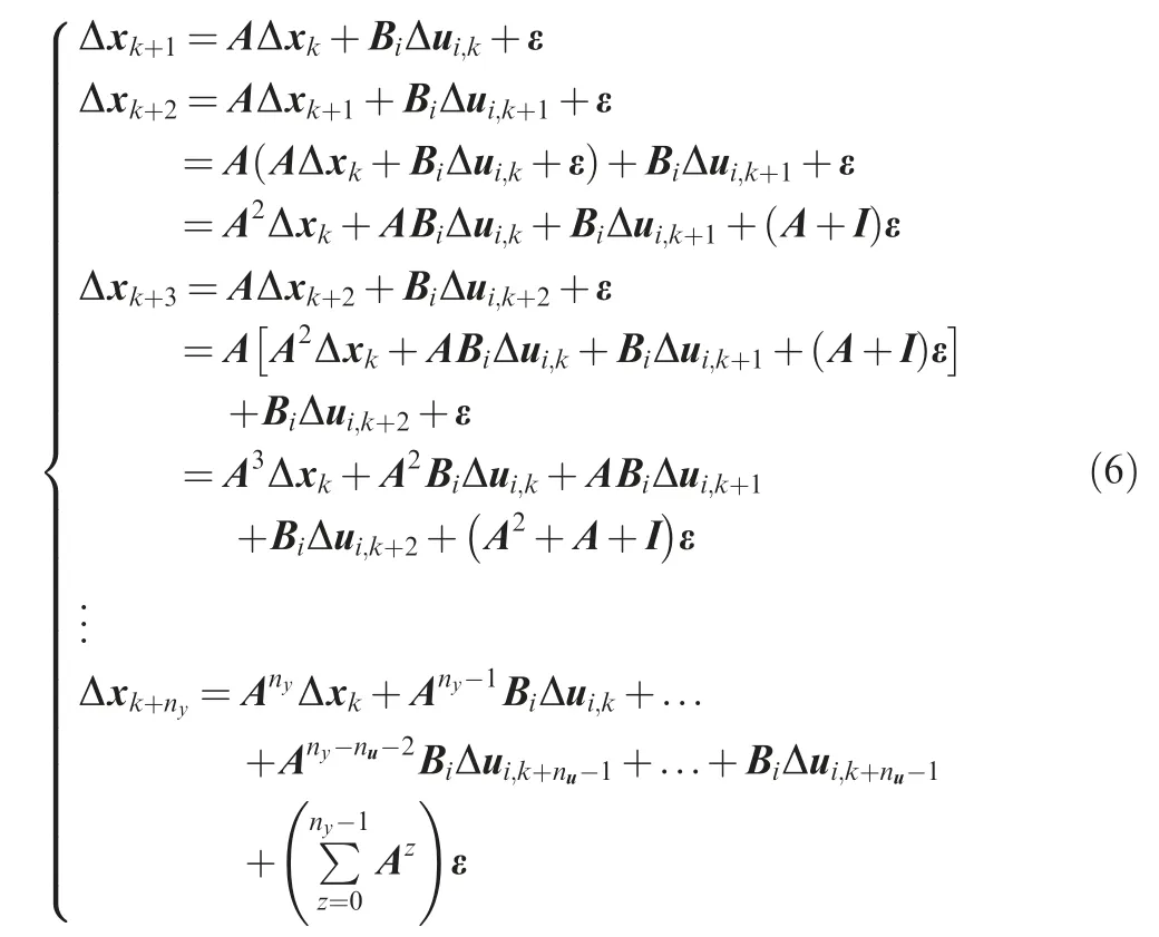
where Bis the corresponding block of B with the input uB = [B,B,...,B,...,B].
In Eq. (6), the state vectors are predicted by the input vector uand the corresponding input matrix B,and the state vector of next future time instant is based on the prediction of the state vector of last future time instant, for example, Δxdepends on Δxpartly,but finally all the predicted state vectors can track back to Δx.
Base on the state vector predictions, the output vector predictions can be given by using the output equation in a similar way.
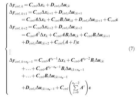
where D= [D,D,..., D,...,D].
As a result, the prediction of controlled variables and constrained variables can be given as

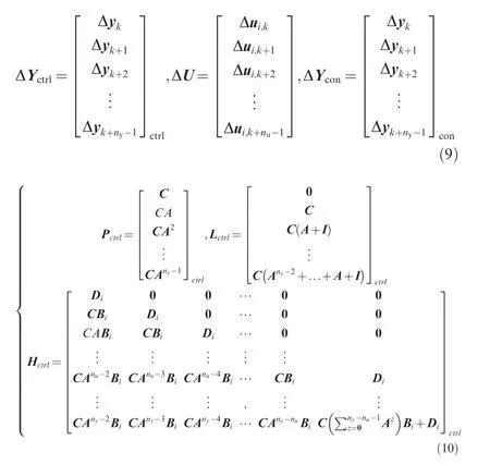
The P, Land Hcan be given in a similar form to P, Land Hshown in Eq. (10). Normally, thrust F is the most important parameter for an aero gas turbine engine,thus thrust is selected as a controlled variable to achieve the direct thrust control. Besides, the fan surge margin SMalways witnesses a larger change than the compressor surge margin SM, and it is also a critical parameter to indicate whether the engine is operating in an extreme condition.Thus,SMis also selected as a controlled variable to be controlled together with thrust F.

Besides that, the dimension of the state vector is two, and the dimension of the constrained parameter vector is s, so the dimensions of prediction matrices are For the constrained parameters,their limits cannot be broken during the engine operation. Thus, these parameters cannot go beyond their upper limits and lower limits.

Besides that,there are upper limits and lower limits for control signals as well as the actuators.

where G and Γ are the transition matrices as

It should be noted that U, U, Uand Uare dynamic because the control variable considered in the control sequence is different for every simulation time instant.
3. Objective function for different thrust control mode
3.1. Normal thrust control
For the normal control issue, the controller should drive the engine to produce the desired thrust according to set-point commands, thus the thrust control error should be considered for this task.
Because an optimization process is conducted in an MPC controller, the control error can be considered in the objective function. Normally a quadratic performance index that contains control errors and the energy consumption is selected.

where eis the control error defined as

where ris the command vector over the prediction horizon,and

The optimization task in the controller is to minimize this objective function, which means that the control objective is to drive the engine to operate at the point defined by the command with minimum energy consumption. In this objective function, control error and the control energy are balanced by two coefficient matrices. In other words,larger matrices Q imposes stricter control error requirements, while larger matrix R denotes less energy consumption. Usually, these elements can be fine-tuned after trialand-error. Consequently, the normal control issue can be addressed when this objective function is implemented in the MPC controller.
3.2. Maximum thrust mode
In most cases, thrust should be controlled to track its command.However,in extreme operating conditions(e.g.aborted landing),thrust should be increased as much as possible to satisfy special demands in comparison with that of the normal operating state. Thus, it is necessary to develop a method to maximize the thrust during the flight mission. Given that a specific control objective can be achieved in a MPC controller by the selected objective function,modification of the objective function is a feasible approach.
Thus, a new objective function is defined as following to maximize the thrust during the engine operation.

It should be mentioned that the control error eof Eq.(18) is almost the same as ein Eq. (16) except that the control error of thrust is not included, so the thrust command is not considered in this objective function. As a result, the thrust command is not a necessary item in this control mode.Instead, an item representing the maximum thrust is added to replace the control error of thrust. There is no doubt that the objective function tends to a smaller value when the item related to thrust is increased.Thus,the minimum of this function can be reached when the thrust reaches the maximum and other controlled parameters track their commands well.Moreover,there is no need to change any part of the proposed controller’s structure when the objective function is changed to conduct this control mode.It brings the benefit that this objective function and the objective function shown in Eq. (15)can be switched from each other easily, namely the normal thrust control mode and maximum thrust mode can be changed from each other smoothly.
Thus, the proposed MPC controller can be presented as

4. Simulation
4.1. Simulation case
To demonstrate the effectiveness of the proposed method, the MPC controller is implemented to a twin-spool gas turbine engine, in which the fan component is linked to the lowpressure turbine through the low-pressure shaft while the compressor component is linked to the high-pressure turbine through the high-pressure shaft. The state-space model is updated continuously from a high-fidelity Linearized Kalman Filter(LKF)based component-level model of which modeling details can be found in Ref.47.Then,the generated state-space model is used as the predictive model and introduced into the online optimization process.
In this case,F and SMare selected as the controlled variables.The command of F is given by a pre-designed thrust control schedule and the command of SMis a constant,namely r=10%,which means that the fan surge margin is kept at a certain level. N, N, SM,SMand the inlet temperature of high-pressure turbine TIT are considered as limited parameters. The limits for these parameters are N≤1.05,N≤1.05,SM≥5%,SM≥5%,TIT ≤1.05.It should be mentioned that SMis not only a controlled variable but also a limited parameter, because its lower limit should not be broken during the transient operation. Note that all the parameters are normalized to the design point except two surge margins.Besides that,the system noise and the measurement noise are considered, of which covariance are both 0.002× I.
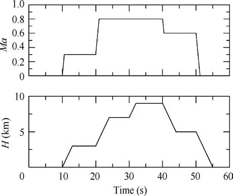
Fig. 2 Flight condition in simulation.
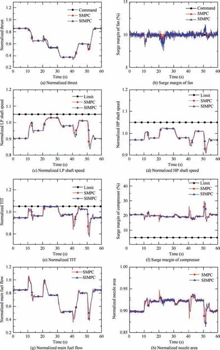
Fig. 3 Responses and changes of control variables in flight envelop.
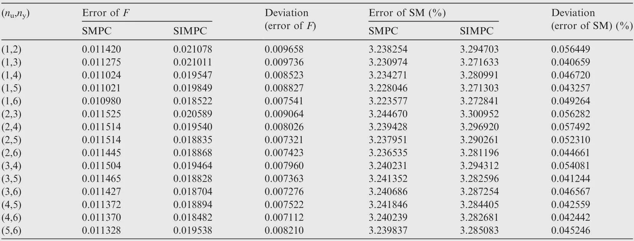
Table 1 Control error with SMPC and SIMPC controller.
Besides,the sampling period is 20 ms,and the simulation is conducted in the flight envelope as shown in Fig. 2. Note that the unit of horizon axis is second (s) rather than minute (min)because this flight condition change is used for demonstrating the effectiveness of the proposed direct thrust control method for different flight conditions rather than for simulating a complete flight mission.
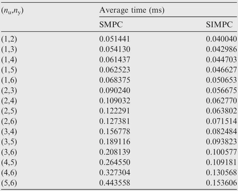
Table 2 Time consumption of optimization process.
4.2. Results analysis
Firstly, the simulation results about normal direct thrust control are given in this subsection to show the control outcome and the advantage of time-consumption of the proposed control method. Given that the proposed method is a reduceddimensional variant of the Standard MPC (SMPC), the control outcome under the SMPC controller is given for comparison.
Fig. 3 shows parameter responses and control variable changes during the simulation when the control horizon and the prediction horizon are 3 and 6 respectively. The weight Q and R are set to diagonal matrices, and the weights for thrust F and SMare 5 and 1, and the weights for control variables, namely for main fuel flow mand nozzle area A,are both 1.Legend‘‘SIMPC”denotes the response of the proposed MPC controller.
Effective command tracks and constraint management can be achieved by both SIMPC and SMPC controllers. Controlled parameter responses under the proposed SIMPC controller and those under the SMPC controller can track the command well although changes of control variables are a little different in some transient operations.For example,at simulation instant 50 s, thrust response speed under the SIMPC controller is a little slower than that under the SMPC controller, it is because only a control variable is allowed to be changed every simulation time instant in the SIMPC controller while two control variables are changed together in the SMPC controller.This is in accordance with changes of main fuel flow and nozzle area shown in Figs.3(g)and(h), which shows that these two control variables change faster when the SMPC controller is implemented. However, it should be mentioned that the increase of control error caused by this feature of the SIMPC controller is small and acceptable while the SIMPC controller gains a significant advantage in reduction of time consumption in comparison with the SMPC controller.
Table 1 compares the control error with the SMPC controller and that with the SIMPC controller. The control error of thrust is judged by RMSE that is calculated by Eq. (20),while the control error of SMis judged by the percent deviation between the command and responses shown in Eq. (21).The columns ‘‘Deviation” compare the control errors under the SIMPC controller with that under the SMPC controller.

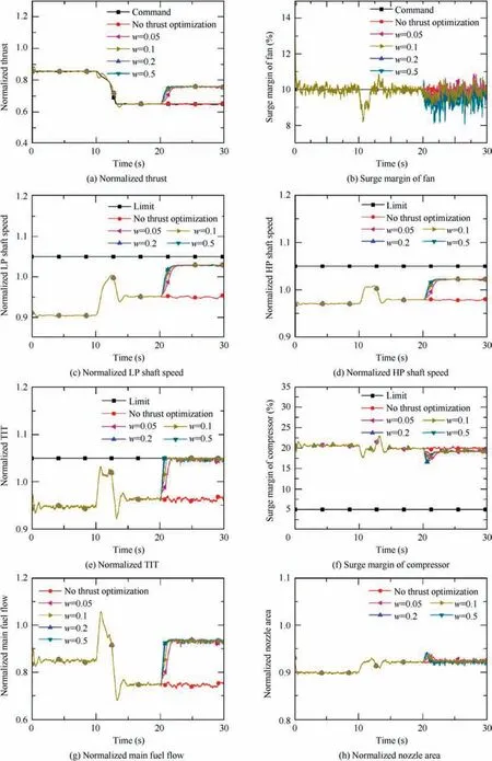
Fig. 4 Maximum thrust during cruise period.
Table 1 shows that the control error of the proposed method is only a little larger than that of the SMPC controller,which demonstrates the control effectiveness of the proposed method. Concretely, the SMPC achieves the minimal RMSE of thrust (0.010980) when the control horizon and predictive horizon are set to 1 and 6, while the RMSE of thrust under the proposed SIMPC controller is 0.018522, which is only 0.007541 larger than the RMSE the former controller achieves.For fan surge margin SM, the minimal control error under the SMPC controller is 3.223577% when (n,n)=(1,6) while that of the proposed one is 3.271303% when (n,n)=(1,5),which is only 0.047726% larger. Furthermore, the deviations of thrust control error only vary from 0.007112 to 0.009736,and the deviations of SMcontrol error fluctuate from only 0.040659% to 0.057492%. Thus, the deviations of control errors between the SMPC controller and the proposed SIMPC controller are very small, which means that the control outcome achieved by the SIMPC controller is very close to that achieved by the SMPC controller.
To compare the time required for the optimization process of the proposed SIMPC controller with that of the SMPC controller,the time consumption is recorded and listed in Table 2.Note that the time consumption test is conducted on a Windows operation system based laptop. Although the time consumption recorded cannot show the real real-time property of both controllers, it still supports the comparison because all the tests are based on the same device, which means that the same test baseline is implemented. The ‘‘Average time”in Table 2 denotes the average time consumption defined as Eq. (22).
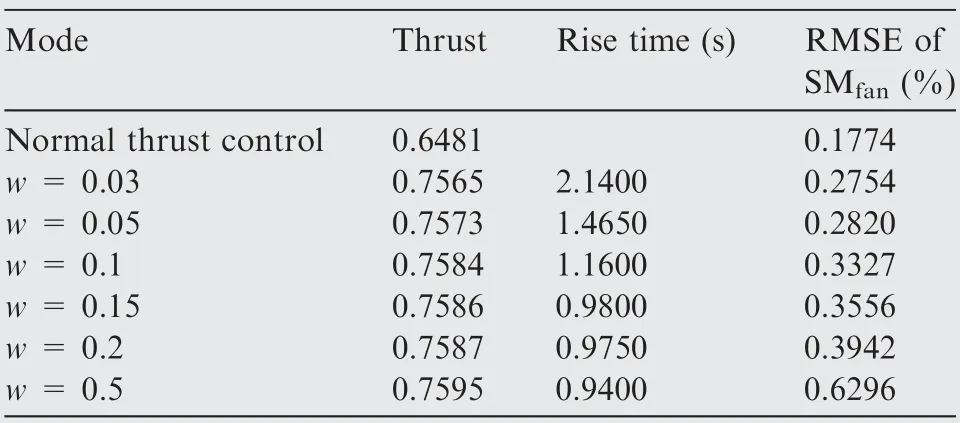
Table 3 Engine performance reached when maximum thrust mode is implemented.

Table 2 shows that the time consumption of both controllers witnesses an increase when the control horizon increases,but the average time consumption of the SMPC controller is larger than that of the SIMPC controller when the same parameters setting is implemented. For instance, the average time of the former controller is about 1.3-2.9 times the latter controller.Besides that,the SMPC controller experiences a more significant increase than the SIMPC controller.For example, the average times of the SMPC controller and SIMPC controller are close (0.068375 ms and 0.050653 ms respectively) when the control horizon and prediction horizon are 1 and 6. However, the average time consumption rises to 0.443558 ms and 0.153606 ms respectively. It means that the former one increases 6.5 times while the latter one only increases 3.0 times, which shows the superiority of the proposed method in time consumption.
4.3. Maximum thrust mode
To demonstrate the effectiveness of the proposed method for maximum thrust mode, this method is implemented in different cases.The first and second cases are to maximize the thrust at a steady-state operating point (cruise) and during the transient operation(climb period),and the third one is to maximize the thrust during the whole simulation. The forth case is to maximize the thrust at simulation time 10-20 s and 50-60 s but to activate the normal thrust control mode at other simulation time, which aims at showing the capability of switch between these two control modes.
For the first case, the flight condition change from 0 s to 20 s is as same as the change from 0 s to 20 s shown in Fig. 1, but the flight condition is unchanged after 20 s. Then,the thrust optimization is activated from 20 s when the engine is at a steady-state point.The weights are 5,1,1,1 for thrust F,SM,mand Ain Eq.(15)respectively,while they are 1,1,1 for SM, mand Ain Eq. (18) respectively.
Fig. 4 shows the engine parameter responses and control variables’ changes with different thrust coefficients w for the first case.The legend‘‘Command”is the commands for thrust and fan surge margin, ‘‘No thrust optimization” denotes the parameter response when only the objective function shown in Eq. (15) is implemented. Table 3 shows the engine performance reached when the maximum thrust mode is implemented.
It is noted that thrust is increased significantly when the objective function for the maximum thrust mode is implemented, and different thrust responses are achieved when different coefficients w are implemented. Fig. 4 shows that the thrust can be increased more quickly when a larger coefficient is selected,and it is in line with the rise times of thrust control shown in Table 3.The rise time is 2.1400 s when w=0.03,but it decreases to 0.9400 s when w is increased to 0.5, which suggests that the proposed controller can adjust the rise time by selecting different coefficients with respect to item of maximum thrust in the objective function.Besides,the change of rise time decreases when the coefficient w increases. For instance, the time decreases by 0.3050 s when w rises to 0.1 from 0.05, but it only goes down by 0.035 s when w jumps from 0.2 to 0.5.
Besides that, there is an overall trend that a larger coefficient can lead to a larger terminal value of thrust. In other words,generally a better optimization of thrust can be reached with a larger coefficient(Table 3).For example,the thrust after optimization is larger than the original thrust level at steadystate, varying from 16.7% to 17.2% larger with increasing coefficients.In contrast,the surge margin is controlled satisfactorily to track the command of fan surge margin although the RMSE of SMincreases when w increases. This is because the larger w means that a relatively smaller coefficient of the control error of SMis considered in the objective function.This is reasonable as the maximum thrust mode aims at maximizing the thrust by making full use of any potential engine parameter margins. For example, the LP shaft speed and HP shaft speed rise to more than 1.0,and TIT is increased to reach its limit line, while there is a large limit margins of these parameters left when the engine is controlled by normal thrust control mode.
For the second case, the flight condition change is as same as the first case, but the maximum thrust mode is started at 10 s, which means the thrust is optimized during the transient operation.The weights are 5,1,1,1 for thrust,SM,m,and Ain Eq.(15)respectively,while they are 0.2,1,1,1 for thrust,SM, m, and Ain Eq. (18) respectively. Fig. 5 shows the engine parameter responses and control variables’ changes for this case. The legend ‘‘Maximum thrust at 10 s” denotes the parameter response when the thrust is optimized from 10 s, ‘‘Maximum thrust at 20 s” denotes the parameter response when the thrust is optimized from 20 s, namely after being steady-state.
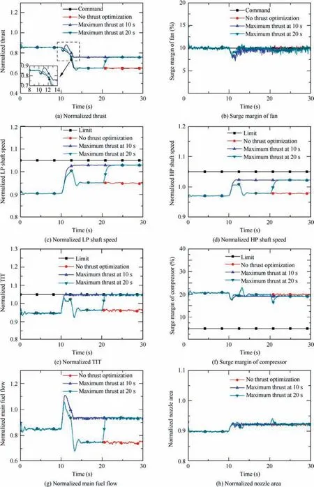
Fig. 5 Maximum thrust during transient operation.
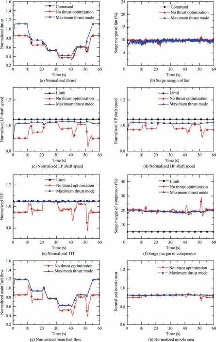
Fig. 6 Maximum thrust during whole simulation.
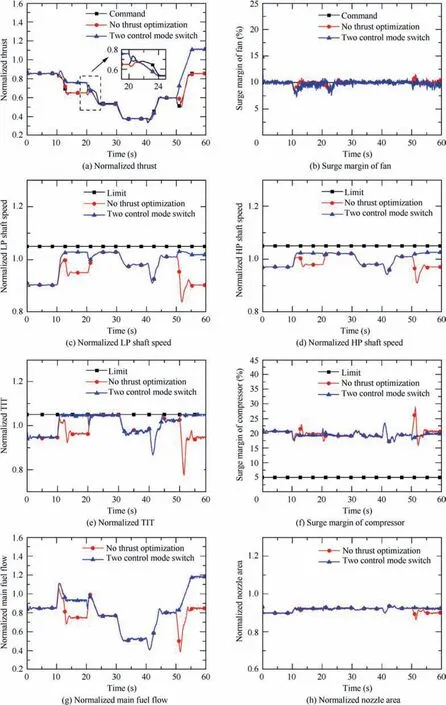
Fig. 7 Two control mode switch during whole simulation.
Fig.5 shows that the thrust can be optimized greatly during the transient operation,which suggests the proposed controller also can optimize the thrust during the transient operation.This optimization is also achieved by driving various limited parameters to close to their limits.Besides,the thrust and other parameters finally reach a very close level either starting maximum thrust mode from 10 s or starting it from 20 s when the flight condition is unchanged. For example, the thrust of the former is 0.7585 at the final 5 s while that of the latter is 0.7587. Similarly, the LP shaft speed and HP shaft speed of the former are 1.0288 and 1.0223 respectively while those of the latter are 1.0289 and 1.0224.These suggest the effectiveness of the proposed method either during a transient operation or at a steady-state operating point.
Fig. 6 shows the parameter responses and control variable changes when the thrust optimization is activated during the whole simulation.
It is noted that the proposed controller for optimizing thrust can be effective in the flight envelope as thrust can be much larger than that when no thrust optimization is implemented. For example, the thrust commands are 0.8548,0.6506, 0.3782, 0.5974 and 0.8547 at the steady-state points during the period of 0-10 s, 10-20 s, 30-40 s, 40-50 s and 50-60 s respectively, but the thrust can reach the peak of 1.1116, 0.7591, 0.4284, 0.6229 and 1.1105 respectively, with 30.04%, 16.68%, 13.27%, 4.27% and 29.93% increases.Accordingly, various parameters become much closer to their limit lines in comparison with the responses when thrust is not maximized.Note that for the period of 20-30 s,the thrust level achieved by the normal thrust control mode and maximum thrust mode is the same. This is because the upper limit of TIT has been reached under the normal thrust control mode. In other words, there is no engine potential that can be used to increase the thrust anymore.
In addition, Fig. 7 shows parameter responses and control variable changes under the forth case.
Fig. 7 shows that two control modes can switch from each other effectively. It can be found that when the maximum thrust mode is activated, the thrust can increase significantly,while this mode is turned off the thrust response can track the command well. For example, the maximum thrust mode is turned off at 20 s,then the thrust decreases towards the command and it becomes as same as the thrust response that is controlled by the normal control mode during the whole simulation after about 21 s.
Overall, the above four cases demonstrate that the thrust optimization based on the proposed MPC controller is effective,which extends the application of MPC controller on aero gas turbine engines. The maximum thrust mode can be activated effectively both in transient operation or steady-state operation,and the switch between normal thrust control mode and the maximum thrust control mode is simple and completely practical. Besides, it should be mentioned that the amplitude of thrust increase depends on the originally designed thrust command.There is no doubt that a much larger increase can be attained if the original thrust command is relatively small because the smaller original thrust command always leads to a larger limit margin, namely the gap between limited parameters and their limits, to be fully developed. Thus, it should be mentioned that the capability of optimizing the thrust by using the potential margins sufficiently rather than the capability of maximizing the thrust more than a certain amplitude is investigated and demonstrated in this subsection.
5. Conclusions
(1) A novel reduced-dimensional MPC controller is presented and implemented to achieve the direct thrust control in the concept of model-based control.By comparing with standard MPC controller,the computation burden of the proposed method is significantly reduced by redefining the control sequence to optimize only one control variable at every simulation time instant. Thus, the dimension of the control sequence is decreased significantly,which leads to a reduction in the scale of the optimization problem that needs to be solved.
(2) This proposed MPC controller is further developed to not only complete normal thrust control tasks but also realize thrust optimization, which extends the function of the MPC controller on the gas turbine engine control. The former aims at driving the engine to operate following the given command with a quadratic performance objective function. The latter aims at fully developing the capability of the proposed MPC controller to maximize the thrust based on the feature of optimization. A different objective function is defined to maximize the thrust according to current operating points online without any modification of the controller in comparison with the controller for normal thrust control mode.
(3) The proposed method is implemented to a twin-spool turbofan engine to achieve different direct thrust control modes. Different control horizons and prediction horizons are implemented in this proposed MPC controller,and a comparison of time consumption is conducted based on the simulation in the wide flight envelope. In the terms of average time consumption, a 20.59% to 65.37% reduction is achieved by the proposed MPC controller in comparison with that of the standard MPC controller. This demonstrates the effectiveness of the strategy that reduces dimension of control sequence in the MPC controller.
(4) The normal thrust control mode and maximum thrust mode is demonstrated by simulations. Particularly,different thrust coefficient for the objective function of maximum thrust mode is investigated, which denotes that this coefficient can be a useful parameter to adjust the rise time and thrust level in maximum thrust mode.The thrust optimization in four different cases demonstrates that two thrust control mode can be switched smoothly. For all modes, the parameter control and constraint management can be achieved, and the maximum thrust mode can increase the thrust while the limits are still not violated.
(5) As the maximum thrust control mode is achieved in this paper, it would be interesting to investigate the method to achieve more intelligent control modes in the future research, such as the minimum specific fuel flow consumption mode, the minimum HPT inlet temperature mode and so on. It is also worthwhile to investigate the possibility of using more advanced predictive models, such as deep neural networks and so on, and constructing a higher order nonlinear optimization problem to achieve a better thrust optimization in the maximum thrust mode.
The authors declare that they have no known competing financial interests or personal relationships that could have appeared to influence the work reported in this paper.
This study was supported by China Scholarship Council (No.201906830081).
