Interfacial characteristics in CNTs-AgCuTi systems
Duo LIU, Bin CHEN, Guoio JIN, Ynyu SONG, Qi ZHANG,Xioguo SONG, Jin CAO,*
a State Key Laboratory of Advanced Welding and Joining, Harbin Institute of Technology, Harbin 150001, China
b Shandong Provincial Key Laboratory of Special Welding Technology,Harbin Institute of Technology Weihai,Weihai 264209,China
KEYWORDS AgCuTi;Carbon nanotubes;Composite filler;Interfacial reaction;Microstructure;TiC particles
Abstract AgCuTi-based composite fillers reinforced with Carbon Nanotubes (CNTs) were prepared by mechanical ball milling and ultrasonic agitation. The morphological features, chemical components, and melting characteristics of the composite fillers with different content of CNTs addition were investigated using Field Emission Scanning Electron Microscopy (FESEM), XRay Diffraction (XRD) and a Differential Scanning Calorimeter (DSC). After being heated at 900 ℃,the microstructure of the composite fillers was examined through FESEM and Transmission Electron Microscopy(TEM)to analyze the interfacial characteristics in the AgCuTi-CNTs system.The microstructures of the composite fillers with 0.5 wt% CNTs and 0.1 wt% CNTs were compared.It was found that 0.5 wt%CNTs were favorable for dispersive distribution of the structure.Nano-sized TiC particles formed in the reaction of CNTs with Ti,resulting in the transformation of TiCu2 with high Ti content and Ti2Cu3 phases to TiCu4 phase with low Ti content. Additionally,the microstructure evolution of the composite fillers was studied by changing the ratio of Ti/CNTs.Results showed that CNTs significantly influenced the wettability of the AgCuTi filler. After addition of 0.3 wt%of CNTs,the spreading area of the composite filler on the C/C composite increased by 146.0%.
1. Introduction
The brazing method, with low cost-effectiveness, convenience,and excellent joining performance, has gained extensive application in aeronautics and space industries, such as C/C composite/TC4,SiO/TC4,glass-ceramics matrix composites/Ti60,and cBN.Brazing has exhibited unique predominance in overcoming the metallurgical incompatibility between dissimilar materials, particularly for ceramics and metals, therefore becoming a flexible and simple joining method for dissimilar materials.
Active metal brazing technology is based on the wetting and reaction of ceramics with active elements at high temperature to achieve bonding between the ceramics and metals.This technique has been extensively used in ceramic/metal components requiring strength, gas tightness and corrosion resistance.For active brazing, the type and concentration of the added active element in the brazing alloy are pivotal to reliable joints.AgCuTi alloys containing eutectic AgCu alloy and a few percent of Ti as the active element are the most commonly used active brazing alloys for the strong bonding of ceramic/metal components. Ti derived from the AgCuTi system has a large thermodynamic driving force to react with most ceramics, leading to the formation of a strong metallurgical bond interface. Currently, AgCuTi alloys have been successfully applied to the bonding of various ceramics and metals such as SiO/TC4,SiC/FeNi42,AlO/Fe-Ni-Co,SiN/Kovar,Ti/ZrO,SiO-BN/Invar,C/LAS composite/TC4,SiBCN/TC4,ZrC-SiC/TC4and C/C composite/Cu.
As a material that has attracted much attention, Carbon fiber reinforced Carbon matrix composites (C/C composite)have a low Coefficient of Thermal Expansion (CTE), good anti-fatigue ability, high thermal conductivity, and hightemperature mechanical properties, thus widely utilized in solid rocket engine nozzles, spacecraft heads and wing leading edges, and fighter brake materials.Strong bonding of C/C composites-metal components can be realized by AgCuTi brazing alloys.However, the dramatic difference in the CTE between C/C composites and metals or brazing alloys was the main cause of cracks inside the reaction layer that impair the joint integrity. Adding low CTE materials (e.g. particles and fibers) into the brazing alloys has been proved successful in relieving the residual stress induced by the CTE mismatch to improve the joint and interface strength. Moreover, it was reported that the reinforcements fabricated by the in-situ synthesis in the brazing process exhibited outstanding reinforcing effects because of their fine size, uniform distribution and favorable cohesion with the matrix.Recently,the in-situ synthesis of TiB whiskers,TiN particles,TiC particles,TiSiparticles were obtained during the brazing process by introducing h-BN,carbon fibers,BC,diamonds,and SiNinto the AgCuTi brazing alloys.These in-situ formed products were beneficial in reducing the residual stress and reinforcing the mechanical properties of the joints, and the obtained joint strength was much higher than that of the joint brazed products using AgCuTi alloys.
The wettability of filler alloys on non-metallic substrate is crucial for the metallurgical process of nonmetallic-metal joining. Zhang et al.developed a carbothermal reduction reaction approach using a Phenol-Formaldehyde (PF) resin as the carbon source to help improve the wettability of the AgCuTi-SiO/SiOsystem. Consequently, the contact angle of the AgCuTi-SiO/SiOsystem dropped from 120° to 30°.Qi et al.adopted a method of preparing a graphene coating on the quartz fiber reinforced silica (SiO/SiO) composite to significantly reduce the contact angle of the AgCuTi filler on the composite from 131° to 45°. Song YY et al.found that adding Graphene Nanosheets (GNSs) to the AgCuTi filler decreased the wettability of the filler on C/C composites; Li et al.prepared Ni nano coatings on the surface of CNTs to improve the wettability of the composites.
With excellent mechanical properties,low density and a low CTE, CNTs are suitable for preparing novel composites.Kumar et al.have fabricated and investigated the Snbased composite reinforced by CNTs, showing that the addition of CNTs can dramatically improve the tensile strength and hardness of the solder matrix. Nai et al.discovered that the addition of CNTs improved the wettability and decreased the average CTE of the solder matrix, both of which are conducive to the brazing of ceramics and metals.Song XR et al.adopted the TiCuZrNi filler with CNTs as brazing alloys and studied the effect of CNTs content on the mechanical properties of C/C composites/TC4 brazed joints. The shear strength of the joints using 1 wt% CNTs was 73% higher than that of the joints without CNTs, while decreased by 82% when the content of CNTs increased from 1 wt% to 3 wt%. Therefore, it is feasible to fabricate CNTs-reinforced brazing alloys for the joining of ceramics with metals. Here we report the AgCuTi-based composite filler reinforced by CNTs fabricated with the mechanical ball milling and ultrasonic agitation mixing process. The effects of CNTs content on the morphology,phase formation, wettability and melting characteristics of the composite filler were investigated,the interface of the composite filler characterized, and the microstructure evolution of the composite filler interface with the content of Ti and CNTs studied.
2. Experimental materials and procedure
Ag-28Cu (wt%)/Ti powders with an average diameter of 10 μm (supplied by Changsha Tianjiu Metallic Material Co.,Ltd, Changsha, China) and Multi-Walled Carbon Nanotubes(MWCNTs) with an average diameter of 8 nm and length of 5-10 μm (supplied by HIT & Yunshan Group Research and Development Center of Graphite Area, Weihai, China) were used as the matrix filler and the reinforcement, respectively.Fig. 1 depicts the detailed fabrication procedure of the CNTs-AgCuTi composite filler, including the following steps:(A) AgCu and Ti powders were added into the acetone solution and the mixture was uniformly dispersed by ball milling;(B) The obtained mixture was dried at 80 ℃for 30 min and grinded to obtain the AgCuTi filler; (C) The AgCuTi filler was added into the homogeneous CNTs suspension prepared by ultrasonic. Then the CNTs-AgCuTi composite filler was fabricated by ultrasonic agitation and dried afterwards.
The C/C composite (17×17×5 mm) was wetted with 50 mg of AgCu4.5Ti-xCNTs (x=0 wt%, 0.3 wt%, 0.5 wt%)composite filler in a vacuum wetting furnace.First,the furnace chamber was evacuated to 5×10Pa and preheated to 200°C. Subsequently, the vacuum chamber was heated to 780°C at a rate of 10°C/min and maintained for 10 min to obtain a uniformly heated sample. Finally, the temperature was increased to 900°C at a rate of 4°C/min.Perform at least three repetitions to ensure the repeatability of the experimental results (Fig. 2).

Fig. 1 Fabrication process of CNTs-AgCuTi composite filler.
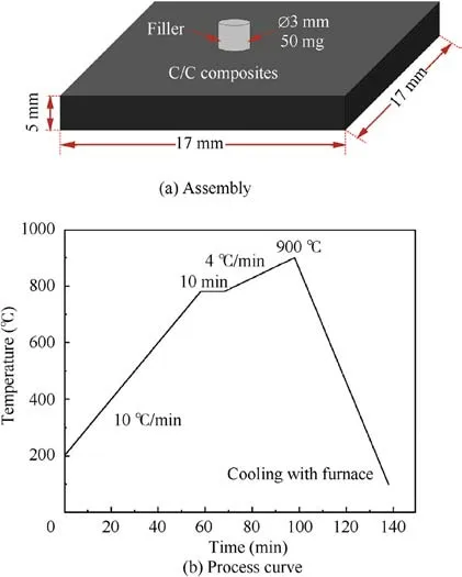
Fig. 2 Wetting experiments.
Field Emission Scanning Electron Microscopy (FESEM,MERLIN Compact, Zeiss) equipped with Energy Dispersive Spectrometers (EDS, OCTANE PLUS, EDAX) was used to investigate the morphology and chemical compositions of the CNTs-AgCuTi composite filler. X-Ray Diffraction (XRD,DX-2700)with Cu-Kα radiation was employed to characterize the phase compositions of the composite filler. A Differential Scanning Calorimeter (DSC, 1/1600) was used to analyze the melting characteristics of the composite filler.The morphology and crystal structure of the composite filler after brazing was studied by Transmission Electron Microscopy (TEM, JEOL-2100). TEM samples were prepared by the Focused Ion Beam(FIB, Helios Nanolab600i, FEI). The spread area image was obtained by an optical digital microscope (DSX 510, OLYMPUS),and processed by the image analysis software(Image J).
3. Results and discussion
3.1. Characterization of CNTs-AgCuTi composite fillers
Fig.3 shows the SEM photographs of the mixed AgCuTi filler and CNTs-AgCuTi composite filler containing 4.5 wt%Ti and 0 ~0.9 wt%CNTs,respectively.The AgCu ball has a smooth surface and is in contact with Ti particles after the ball milling process, as shown in Fig. 3(a). The morphologies of the composite filler showed that CNTs (as indicated by the arrow shown in Fig. 3(b)-(f)) were transparent, distributing uniformly in the filler matrix after the ultrasonic agitation mixing process.
The XRD pattern shows that all composite fillers consisted of Ag,Cu,Ti and CNTs peaks,as displayed in Fig.4.Notably,only the intensity of the CNTs peak was promoted with the increase of CNTs content in the composite filler, indicating that no metallurgical reaction occurred during the mechanical mixing process.
The DSC curves obtained from the AgCu4.5Ti-CNTs composite filler doped with different contents of CNTs were presented in Fig. 5. All DSC curves exhibit a well-defined endothermic peak in which the start and peak melting temperature for the AgCu4.5Ti filler was 776.1 ℃and 795.2 ℃respectively, whereas for AgCu4.5Ti-0.1 wt% CNTs the start temperature rose to 777.4 ℃ and the peak temperature dropped to 794.3 ℃. Addition of 0.3 wt% CNTs resulted in lowering the start and peak temperature of the composite filler to 774.8 ℃and 790.1 ℃.This is attributed to the inherent high surface free energy of CNTs which increases the surface instability of the filler.Furthermore,the size effect of CNTs can significantly alter the grain boundary/interfacial characteristics of the filler.In this process, CNTs play a role in retarding the grain growth to result in residually unconsumed grain boundary surface energy and interfacial free energy; thus the grain boundary free energy values in the composite filler are higher than those in the filler matrix which is conducive to the melting of the filler to reduce both the start and peak temperature in the composite filler.In the case of 0.5 wt% addition of CNTs, the start and peak temperature increased to 778.2 ℃and 796.4 ℃,respectively.The possible reasons for the increase in the melting point of the composite filler could be the agglomeration of CNTs in the AgCu4.5Ti-0.5 wt% CNTs composite filler.
3.2. Interfacial characterization between CNTs and AgCuTi
To investigate the interfacial reaction between the reinforcement and the filler matrix in the CNTs-AgCuTi system, the composite fillers with 0.1 wt%and 0.5 wt%CNTs respectively were heated to typical operating temperature (900 ℃ for 10 min)for observation.The morphologies and element distribution images of both composite fillers are shown in Fig. 6,and the corresponding chemical compositions and phases are analyzed by means of EDS and XRD, as shown in Table 1 and Fig. 7, respectively. It can be seen from Fig. 6(a) that the microstructure of the composite filler with 0.1 wt% CNTs mainly consists of the AgCu eutectic structure, the rod-like TiCuphase and the granulous TiCuphase. The precipitation of these reaction products can be expressed by
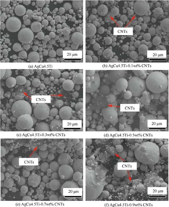
Fig. 3 SEM photographs of AgCu4.5Ti-CNTs composite fillers.
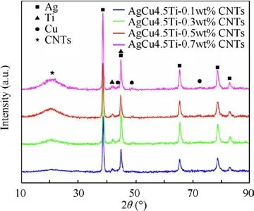
Fig. 4 XRD patterns of AgCu4.5Ti-CNTs composite filler.

where L means brazing melt; (s,s) means solid solution.
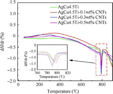
Fig. 5 DSC curves of AgCu4.5Ti-CNTs composite filler.
Note that no CNTs could be observed at the interface,while the TiC phase (PDF#65-8417, d=4.325 A° , where d is interplanar crystal spacing,1 A° =0.1 nm)was detected according to the XRD pattern.The(200)peak of TiC at 2θ=41.73°in Fig. 7 shows that no shift of peak existed, indicating a correct TiC stoichiometry.
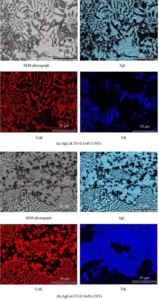
Fig. 6 EDS mappings of Ag4.5CuTi-0.1 wt% CNTs and AgCu4.5Ti-0.5 wt% CNTs composite fillers.
Generally,the negative Gibbs free energy of TiC formation at 900 ℃induces the reaction of Ti and C in the composite filler to produce TiC by


Table 1 Chemical compositions of each spot marked in Fig. 6.
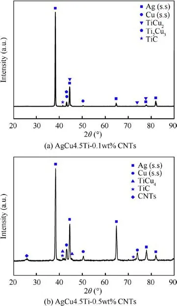
Fig. 7 XRD patterns of AgCu4.5Ti-0.1 wt% CNTs and AgCu4.5Ti-0.5 wt% CNTs.
where ΔGis Gibbs free energy; T is temperature.
The size of the AgCu eutectic structure was reduced when CNTs content in the composite filler was 0.5 wt% as shown in Fig. 6(b), indicating that more CNTs were favorable for the structure of dispersive distribution. Another significant variety was that TiCuand TiCuphases almost disappeared,replaced by the TiCuphase which uniformly dispersed in the AgCu matrix.The possible reason for this phenomenon is that added CNTs consumed more Ti in the original filler, resulting in the concentration reduction of Ti which reacted with Cu.Therefore, the Ti-Cu phase with low Ti content (TiCu) was generated and grew with increasing CNTs content. The nano-sized TiC phase could be formed due to the size effect of CNTs;however,it could hardly be observed at the interface.To study the morphology and crystal structure of the TiC phase,TEM analysis was performed and the result was shown in Fig. 8. According to the TEM photograph (Fig. 8(a)) and the corresponding Selected Area Electron Diffraction(SAED)pattern (Fig. 8(b)), the granular crystal structure about 10-20 nm thick circled in Fig. 8(a) with the red curve was identified as TiC. This confirmed the occurrence of in-situ reaction and formation of the TiC nano-phase in the shape of particles.The above interfacial analyses revealed that the stoichiometry of TiC did not change with the content of CNTs. In addition,the Ti-Cu intermetallic compounds with high Gibbs free energy compared with the TiC phase were more stable, which would grow significantly at high temperature.Typically, the interface with a high plastic deformation structure and uniformly dispersed reinforcements were expected to be obtained in ceramic/metal joining to relieve the residual stress of the joint. Consequently, the ratio of the composite filler composition should be adjusted to match the interface.
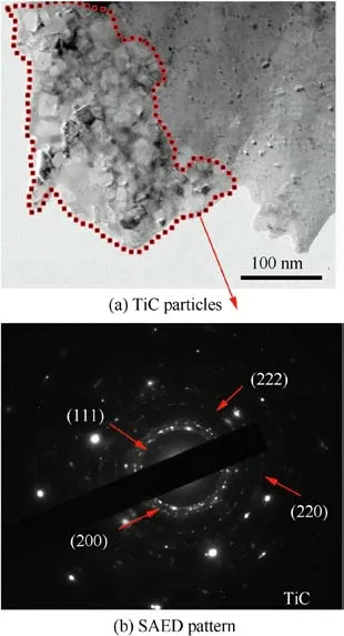
Fig. 8 TEM analysis of TiC.
3.3. Microstructure evolution with varied Ti and CNTs contents
Fig. 9 shows the SEM images of the AgCu4.5Ti-CNTs composite filler with different ratios of Ti/CNTs. It can be clearly observed that the content of Ti and CNTs addition had significant effects on the microstructure evolution and phase distribution. According to Fig. 9(a)-(d), a small number of Ti-Cu phases were observed at the interface, and part of the CNTs remained (Fig. 9(q) and (r)), when the content of Ti was 1.0 wt%. The size effect produced by CNTs could restrain the growth of reaction phases.Therefore,the addition of carbon nanotubes could make the microstructure fine and spread evenly. It has been confirmed that Ti was prone to reaction with CNTs to form TiC nanocrystals. With the increase of CNTs content, more precipitated TiC nanoparticles increased the dispersion of the microstructure and reduced the quantity of Ti-Cu phases.Further increase in CNTs content to 0.5 wt%and 0.7 wt% led to the aggregation of CNTs at the interface.Ti-Cu phases gradually increased when Ti content of the composite filler was increased (Fig. 9(e) and (i)). Similar phenomena such as microstructure refinement and decreasing Ti-Cu phases can be observed at the interface with CNTs addition(Fig. 9(f)-(h), (j)-(l)). CNTs aggregation was also observed at 3.0 wt% Ti and 0.7 wt% CNTs. When the content of Ti reached 7.0 wt%,the Ti-Cu phases occupied almost the whole interface and TiC aggregation was observed(Fig.9(m),(s)).In this instance,the microstructure of the Ti-Cu phase showed little sign of improvement, despite the addition of CNTs (Fig. 9(n)-(p), (s), (t)).
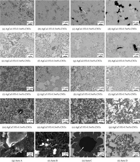
Fig. 9 Morphologies of AgCuxTi-yCNTs (x=1.0 wt%-7.0 wt%, y=0.1 wt%-0.7 wt%) composite filler at 900 ℃for 10 min.
3.4. Wettability of CNTs-AgCuTi composite filler
To study the change in wettability, the macrographs and spreading area of cross-sectional droplets of the AgCu4.5TixCNTs composite filler on the C/C composite were observed,as shown in Fig. 10.The wetting angle of the AgCu4.5Ti filler on the C/C composite was about 6.19°,and the spreading area was 27.08 mm.It can be clearly observed from Fig.10(c)and(d) that after addition of 0.3 wt% CNTs, the wetting angle of the fillers changed significantly,while the spreading area changed considerably—the wetting angle was reduced to 2.60° and the spreading area increased to 66.61 mm(increased by 149.0%). Continuing to increase the content of CNTs to 0.5 wt%, we observed that the spreading area reduced to 26.97 mmand the wetting angle only decreased by 2.59°.
Clearly, with the increase of CNTs content, the wetting models of the fillers gradually deviated from the standard wetting model, and the height of the fillers gradually increased.Although the AgCu4.5Ti filler and the AgCu4.5Ti-0.5 wt%CNTs composite filler had the same spreading area, the wetting models of the two were different. The former approximated the standard wetting model (Fig. (g)), while the latter substantially deviated from the standard model (Fig. 10(h)).Most of the molten AgCu4.5Ti-0.5 wt%CNTs composite filler was confined in the center, with only a small part spreading out. Despite the similar spreading areas, this difference made the wetting angle of the AgCu4.5Ti filler significantly larger than that of the AgCu4.5Ti-0.5 wt% CNTs composite filler.When CNTs were increased to 0.5 wt%, a large amount of TiC and Ti-Cu in the filler constrained most of the molten filler from spreading around uniformly, thereby reducing the spreading area of the filler and deteriorating its wettability.
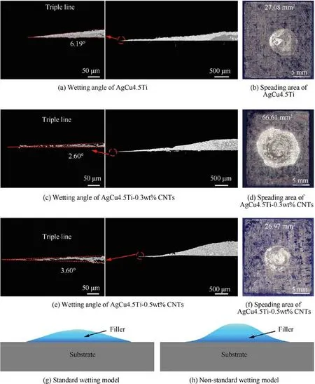
Fig.10 Weeting angel and spreading area of cross-sectional droplet of AgCu4.5Ti-CNTs composite filler on C/C composite and wetting model.
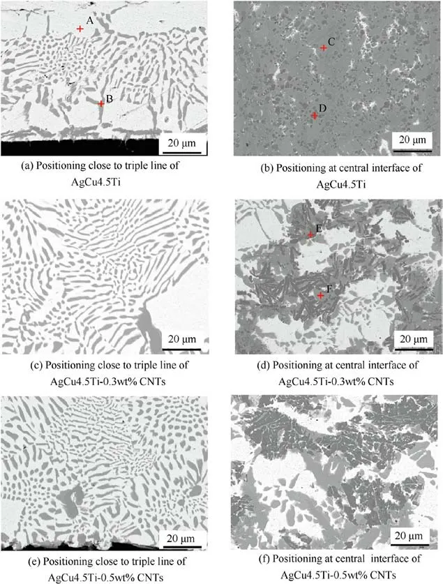
Fig. 11 Microstructure of AgCu4.5Ti-xCNTs composite filler on C/C composite.
The microstructure of the wetted composite filler was observed for further investigation into wettability. Fig. 11 shows the microstructure of the AgCu4.5Ti-CNTs composite filler on the C/C composite,and the EDS results are displayed in Table 2. Comparison of the interface close to the triple line and that at the central region reveals obvious differences between them. For the AgCu4.5Ti filler, the interface (Region i)close to the triple line consisted of a bright white phase and a dispersed gray phase; the interface (Region ii) at the central region consisted of a gray phase, a dispersive dark phase and a small bright white phase. After addition of CNTs, no obvious changes were observed in Region i; in Region ii, the gray phases were largely reduced, the white phases increased, and the black phases concentrated. As the content of CNTs increased, the agglomeration of the black phase became more obvious. It could be inferred that Region i was composed of the AgCu eutectic, the continuous gray phase in Region ii was TiCu, and Ti-Cu compounds were dispersed therein.The addition of CNTs promoted the transformation of Ti-Cu compounds into TiCu. TiC synthesized in situ betweenTi and CNTs became the nucleation particles of TiCu. The agglomeration of TiCuwas also caused by the agglomeration of CNTs. In Figs. 10 and 11, it can be seen that after CNTs were added, the spreading area increased significantly, and the wettability was improved.The aggregated bulk intermetallic compounds in the interface were dispersed into small-sized solid phases. Song XG et al.pointed out that the formation of intermetallic compounds inhibited the wetting of high Ticontaining droplets. Therefore, after addition of 0.3 wt%CNTs, the Ti-Cu compounds in the droplets were dispersed to improve the wettability of the filler.

Table 2 Chemical compositions of each spot marked in Fig. 11.
4. Conclusions
In this work, AgCuTi-based composite fillers reinforced with CNTs were prepared by mechanical ball milling and ultrasonic agitation mixing of CNTs with AgCu and Ti powders. CNTs were evenly distributed in the filler matrix.The morphological feature,chemical component,melting characteristics,wettability of the composite fillers with different content of CNTs additions were analyzed. Conclusions are drawn as following:
(1) Comparison of melting characteristics of the composite filler with those of the pure AgCuTi filler revealed that the melting point of the composite fillers decreased due to the 0.3 wt% addition of CNTs.
(2) Observation of the microstructure of the composite filler obtained at 900 ℃/10 min showed that nano-sized TiC particles were produced through the reaction of CNTs and Ti.With the increase of CNTs content,more precipitated TiC nanoparticles increased the dispersion of the microstructure and reduced the quantity of the Ti-Cu phases, while the high Ti-containing TiCuand TiCuphases transformed into the low Ti-containing TiCuphase. CNTs aggregation was observed when the contents of CNTs/Ti were 0.5 wt%/1.0 wt%, 0.7 wt%/1.0 wt% and 0.7 wt%/3.0 wt%. When the content of Ti increased to 7.0 wt%, Ti-Cu phases occupied almost the whole interface and hardly changed with the increase of CNTs.(3) Since Ti-Cu compounds were dispersed by TiC synthesized in situ with CNTs and Ti, the wettability of the AgCu4.5Ti-CNTs composite filler on the C/C composite was improved. After addition of 0.3 wt% of CNTs, the spreading area of the composite filler on the C/C composite increased by 146.0%.
The authors declare that they have no known competing financial interests or personal relationships that could have appeared to influence the work reported in this paper.
s
This study was co-funded by the National Natural Science Foundation of China (Nos. 51875130 and 51775138) and the Shandong Provincial Natural Science Foundation of China(No. ZR2019MEE091).
 Chinese Journal of Aeronautics2022年4期
- Chinese Journal of Aeronautics的其它文章
- An automatic isotropic/anisotropic hybrid grid generation technique for viscous flow simulations based on an artificial neural network
- Optimization design of airfoils under atmospheric icing conditions for UAV
- Pressure distribution feature-oriented sampling for statistical analysis of supercritical airfoil aerodynamics
- Recent progress of machine learning in flow modeling and active flow control
- Design method of optimal control schedule for the adaptive cycle engine steady-state performance
- Using tandem blades to break loading limit of highly loaded axial compressors
