A novel high-order scheme for numerical simulation of wake flow over helicopter rotors in hover
Shaoqiang HAN, Wenping SONG, Zhonghua HAN
Institute of Aerodynamic and Multidisciplinary Design Optimization, National Key Laboratory of Science and Technology on Aerodynamic Design and Research, School of Aeronautics, Northwestern Polytechnical University, Xi’an 710072, China
KEYWORDS Dynamic overset grid;Helicopter rotors;High-order scheme;Unsteady flow;Vortex flow;WENO scheme
Abstract Accurate prediction of tip vortices is crucial for predicting the hovering performance of a helicopter rotor.A new high-order scheme(we call it WENO-K)proposed by our research group is employed to minimize numerical dissipation and extended to numerical simulation of unsteady compressible viscous flows dominated by tip vortices over hovering rotors. WENO-K is referred to as an adaptively optimized WENO scheme with Gauss-Kriging reconstruction,and its advantage is to reduce dissipation in smooth regions of flow while preserving high-resolution around discontinuities.Here WENO-K scheme is adopted to reconstruct left and right state values within the Roe Riemann solver updating the inviscid fluxes on a structured dynamic overset grid.To minimize the accuracy loss for high-order reconstruction on artificial boundaries of overset grid, a method of multilayer fringes is proposed to carry out interpolation between background grid and blade grid.Massively parallel computing considering automatic load balance on averagely partitioned overset grid is developed to reduce the wall-clock time of an unsteady simulation. Numerical results for Caradonna-Tung (C-T) rotor in hover at the conditions of subsonic and transonic tip Mach numbers show that the thrust coefficient error for the result of WENO-K scheme is no more than 3%.Compared with WENO-JS scheme, WENO-K scheme achieves about 40% improvement on accuracy of predicting rotor thrust with only 4.1% extra computational cost. More importantly,WENO-K scheme can capture more sophisticated unsteady flow structures and resolve tip vortices to a larger wake age with an increment of about 270° compared to WENO-JS scheme.
1. Introduction
Different from a fixed-wing with the generated tip vortex quickly convected to farfield,the strong vortex wake of a helicopter rotor lingers in the vicinity of the rotor all the time. In hover,the strong tip vortex spirals down beneath the rotor and significantly alters the effective angle of attack of blades. In forward flight, the entire vortex wake is swept back, leading to strong Blade-Vortex Interaction (BVI) which is a major source of aerodynamic noise and structural vibration.Actually, all complex aerodynamics, structural dynamics and aeroacoustics for rotorcraft are related to tip vortex. Therefore, accurate modeling of tip vortex is highly related to accurate prediction of aerodynamic performance such as thrust coefficients and induced torque coefficients,which is important for design optimization of rotors.
The majority of CFD methods are not adequate for vortexdominated flows.For example flows around a helicopter rotor,especially in hover, is difficult to model due to the presence of strong vorticity. The additional wake model largely depends on semi-empirical parameters about wake system for specific flow,while the CFD method directly solves the wake systems as part of the solution of Reynolds-Averaged-Navier-Stokes (RANS) equations. Hence, the CFD method is more accurate and particularly useful in analyzing vortex wakes for complex rotors where no experimental data is available. The complexity of flow around a rotor presents great challenges for CFD because of the limitation in grid resolution and the dissipative nature of the numerical methods.To minimize the dissipation errors for vortex and compute as efficient as possible, high-order schemes with low dissipation,high-resolution grids in wake region and massively parallel computing on partitioned grid are indispensable.
The dissipative nature of traditional second-order schemes inevitably lead to excessive vortex dissipation. Clearer rotor wakes are captured by third-order schemes, but still far from satisfactory. Unlimitedly increasing orders are accompanied by excessively growing computational cost, and fifth-order WENO schemes can always be comprehensive considerations to reach a compromise. WENO scheme was initially proposed by Liu et al.and developed by Jiang and Shu(WENO-JS).WENO-JS scheme can achieve the maximal fifth-order accuracy and is more efficient, which established the foundation for the explosive development of WENO. WENO scheme was further improved and extended to much higher orders by Balsara and Shu.Later, Henrick et al.developed the mapped WENO scheme (WENO-M) to recover the maximal order accuracy at critical points. Borges et al.developed the WENO-Z scheme by a new smoothness indicator with less dissipation and higher resolution compared to the classical WENO-JS. Hu et al.proposed an adaptive central-upwind WENO scheme (WENO-CU6), it adapts between the central and upwind schemes smoothly by a new weighting strategy to achieve sixth-order accuracy in smooth regions of flowfield.There is more research about the improved WENO schemes.
The traditional WENO schemes mentioned above are subject to the limitation of excessive numerical dissipation in smooth regions.They are all based on the polynomial interpolation and its convex combination at the cell boundaries,which can only achieve the maximum order of polynomial interpolation when the size of stencil is fixed.Instead of enlarging the stencils with substantially increasing computational cost, Han et al.proposed WENO-K scheme that adopts non-polynomial Gauss functions and Kriging interpolation to improve the order of accuracy for the reconstruction by involving a free hyper-parameter. WENO-K scheme allows the hyper-parameter to be adaptively optimized by using the local solution so that the local accuracy is improved and numerical dissipation can be reduced. At the same time, an effective indicator is constructed to efficiently eliminate the unreasonable hyper-parameters evaluated on troubled cells that contain discontinuities. WENO-K scheme can be easily applied to any improved variants of WENO schemes to enhance their accuracy in smooth regions. In this article, we just implement the initial WENO-K to the classical WENOJS method in order to illustrate its advantages briefly.
Some classical high-order schemes have been applied to capture vortex wakes of rotors,and try to keep the tip vortex based on an acceptable amount of grids. In this paper, the high-order and low dissipative WENO-K scheme is further developed to three-dimensional applications to solve the unsteady compressible viscous flows over helicopter rotors in hover, and capture vortex wakes that better matches with physical significance compared to WENO-JS scheme.
The overset grid system consists of a Cartesian background grid and several body-fitted blade grids. The background grid provides a refined region to keep high resolution for the vortex wake, and grid cells within the region are strictly orthogonal and approximately uniform to ensure that the nominal accuracy of the scheme is preserved as much as possible. A multistart distance decreasing method and a tri-linear interpolation method are adopted to update the variables between background grid and blade grids. It should be noted that we propose multilayer fringes to support any-order flux reconstruction on the hole boundaries and the artificial external boundaries.
The paper is organized as follows:in Section 2,the dynamic overset grid technique with some improvements is presented,which lays the foundation for the application of higher-order schemes and parallel computation. The governing equations and the numerical schemes are described in Section 3. In Section 4, two simulations of flow over a rotor in hover are conducted and results are discussed. Finally, we give a brief conclusion in Section 5.
2. Dynamic overset grid technique
High-quality grid and appropriate treatment for overset boundaries contribute to accuracy preservation for the flow simulation of helicopter rotors by using high-order schemes.Massively parallel computing on averagely partitioned overset grid make it possible to efficiently perform high-accuracy numerical simulation of unsteady flow over rotors on advanced computing platforms.
2.1. Structured overset grid system
Take C-T rotorfor example,the dynamic overset grid system used for discretization of computational domain is composed of a static Cartesian background grid and two blade grids with rotational motion as shown in Fig.1(a).Fig.1(b)and Fig.1(c)show the structured C-H body-fitted grid generated by using transfinite interpolation.Fig.2 gives cut away views of refined region on background grid for wake capture, where the grid keep approximately uniform and strictly orthogonal to guarantee good performance of spatial schemes. According to the widely accepted practiceof grid generation for numerical simulation of rotor flows, we take strict control of the cell height in the first layer (y<1), the distribution of grid on blade tip (Δ <0.2%c), and the cell size in the wake region of interest (Δ <5%c).
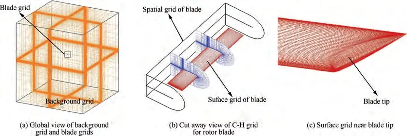
Fig. 1 Computational grid system for C-T rotor in hover.
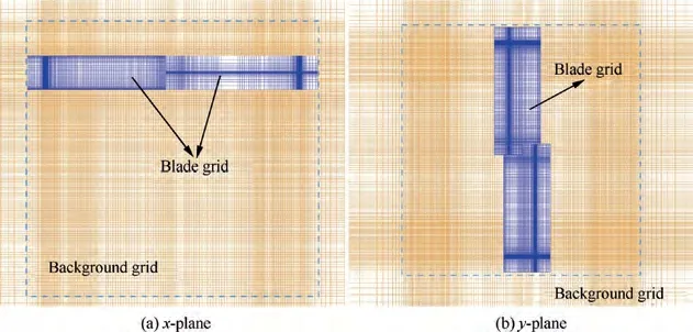
Fig. 2 Cut away view of refined region on background grid for wake capture.
2.2. Identification of artificial boundaries
To achieve information exchange between background grid and blade grids, some different types of cells as shown in Table 1 need to be defined in every part of grid system. The hole is dug out from background grid and tightly cover the rotor blade.The background cells that exactly enclose the hole are defined as hole boundary cells which are responsible for transferring information from blade grid to background grid,while the outer boundaries of blade grid, also called artificial outer boundary cells,are responsible for transferring information reversely. The hole boundary and artificial outer boundary are collectively referred to as artificial boundaries, where the cells are called fringe cells.
The hole boundary cells should be redetermined at every physical time step by using the hole map method.First,a virtual Cartesian grid called hole map is generated to cover the blade as shown in Fig.3.For the sake of simplicity,Fig.4 gives a two-dimensional section view. Second, those background grid cells within the Hole Map are defined as hole cells.Finally, the outer boundary of hole is the new approximate hole boundary.
Considering the WENO scheme requiring a big stencil to build the high-order spatial flux, multilayer artificial boundaries are proposed as shown in Fig. 5 to ensure no accuracy reduction for fifth-order reconstruction in the hole boundaries and the artificial external boundaries.
2.3. Search method of donor cells
The flow variables on the artificial outer boundary cells in blade grid are interpolated from donor cells in background grid. Similarly, the flow variables on the hole boundary in background grid are provide by donor cells in blade grid.Here we proposed a multi-start distance decreasing method algorithm as shown in Fig. 6 to optimize the efficiency and avoid search failure. The multi-start distance decreasing method for identification of artificial boundaries and search of donor cells perform suitably and efficiently on the background grid and blade grid with single block.

Table 1 The cell-type of overset grid for rotor in hover.
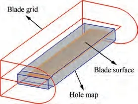
Fig. 3 Hole map formed by virtual Cartesian grid.
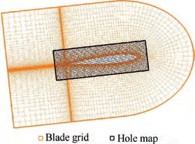
Fig. 4 Schematic sketch of hole map and blade grid.
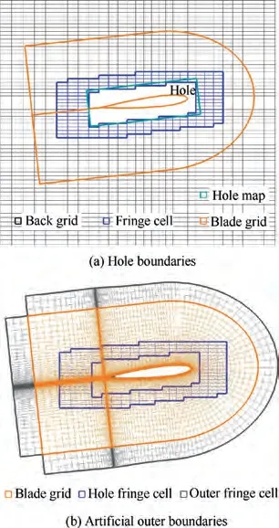
Fig. 5 Schematic sketch of three-layer artificial boundaries on background grid and blade grid.

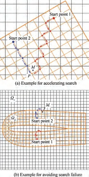
Fig. 6 Schematic sketch of a multi-start distance decreasing method algorithm.
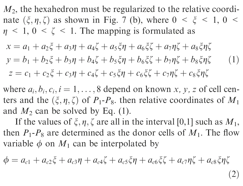
where adepend on known flow variables on P-P.
If any value of ξ,η,ζ is beyond the interval[0,1]such as M(ξ<0), then the indexes (i,j,k) of P-Pshould be minus 1 along negative direction of ξ to construct a new hexahedron and repeat coordinate mapping.
2.4. Arbitrary partition of grid system for parallel computation
Fig.8 gives the flowchart of arbitrary partition for grid system and parallel computation. Here we introduce the process step by step in detail.
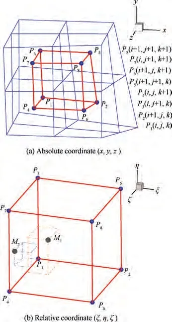
Fig. 7 Schematic sketch of a hexahedron for the tri-linear interpolation.
Step 1.Single-block grid generation.The initial grid system for a two-bladed rotor show in Fig.1 consists of a background grid and two blade grids, and the cell number of background grid is much larger than that of the blade grids. This kind of grid system limits the number of processors used for parallel calculation on grid blocks to no more than 3 without considering load balancing.
Step 2. Arbitrary partition of grid system. In order to achieve efficient parallel numerical simulation considering automatic load balance, the blocks of grid system show in Fig. 1 is averagely divided as shown in Fig. 9 according to the number of processors available.
Step 3.Identification of cell-types and search of donor cells.Conduct the overset technique introduced in Sections 2.2 and 2.3 on the initial grid system and save cell-types and interpolation relation for overset grid. This step goes fast enough by using the multi-start distance decreasing method.
Step 4.Allocate the overlap information generated in Step 3 to the partitioned grid system according to the correspondence between single-block grid and multi-block grid.
Step 5. m sub-processors equally share the grid blocks and perform sub-iterations in parallel, and one main processor is responsible for data interaction between sub-processors.
Step 6. If the physical time t advances to the set t, the unsteady simulation stops. Otherwise, the blade grid will be updated to a new location in physical time t + Δt, then the process will be repeated from Step 2.
Table 2 shows the partition of overset grid system for C-T rotor in hover,where a total number of 18,057,216 grid cells with initial 3 blocks is almost averagely divided into 156 blocks. ID,JD, KD denote cells numbers in three spatial directions for a block of structured grid, and B denotes the number of blocks.156 computing processors and a main processor can be used for parallel computation based on Message Passing Interface(MPI). As show in Fig. 10, each processor treats one or a part of the grid blocks independently, and there may be interfaces between the grid blocks from different processors, which also requires data interaction across sub-processors.
2.5. Study of grid convergence
For the three-dimensional numerical simulation of unsteady flow over rotors, the total number of grid cells required to achieve strict grid independence can be huge, and the corresponding computational cost is unacceptable. Therefore, we perform a simplified study of grid convergence by multiplying the total number of grid cells.
Take the subsonic flows over C-T rotor in hover as example. The spatial scheme used here is 3rd-order MUSCL. Grid refinement is mainly implemented in the blade grid and the wake region of background grid. Fig. 11 gives the change of thrust coefficient Cwith the growth of number of grid cells,which shows a trend of convergence. Table 3 gives calculated thrust coefficients for 4 levels of grid, in which the difference of Cbetween Level 3 and Level 4 is less than 1%.Therefore,we think the grid Level 3 is reliable enough for the simulation of flow over C-T rotor in hover, and the grid systems used in Section 4 in this work also reach this level.
3. Numerical method
3.1. Governing equations
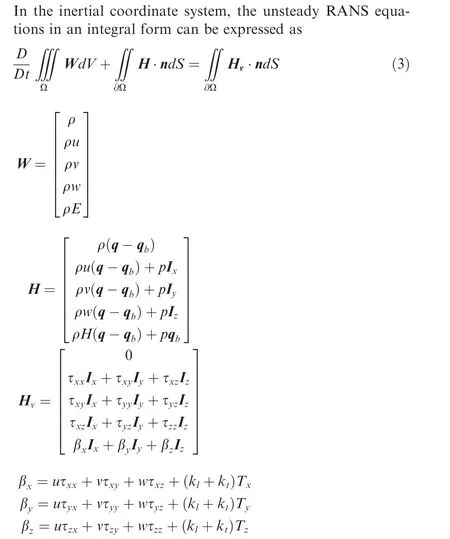
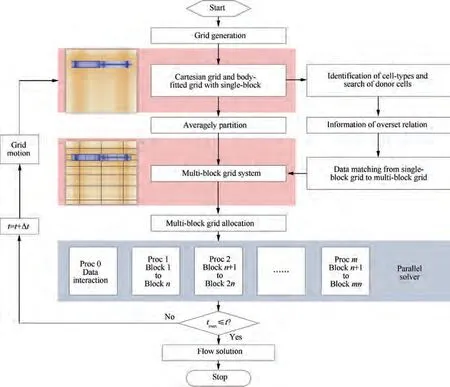
Fig. 8 Flowchart of arbitrary partition for grid system and parallel computation.
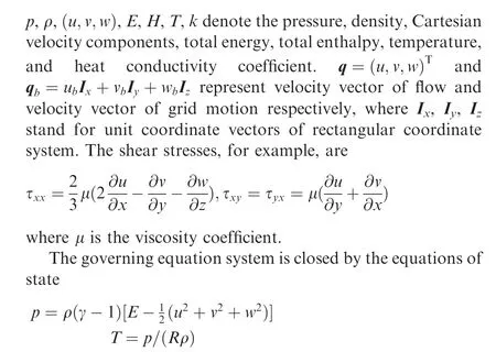
where γ is the ratio of specific heats.One-equation S-A modelis used for turbulence enclosure.
3.2. Spatial discretization
Under the finite volume framework, a system of ordinary differential equations is obtained by applying Eq.(3)to each control volume (i,j,k), which is written as

where the inviscid fluxes and the viscous fluxes are
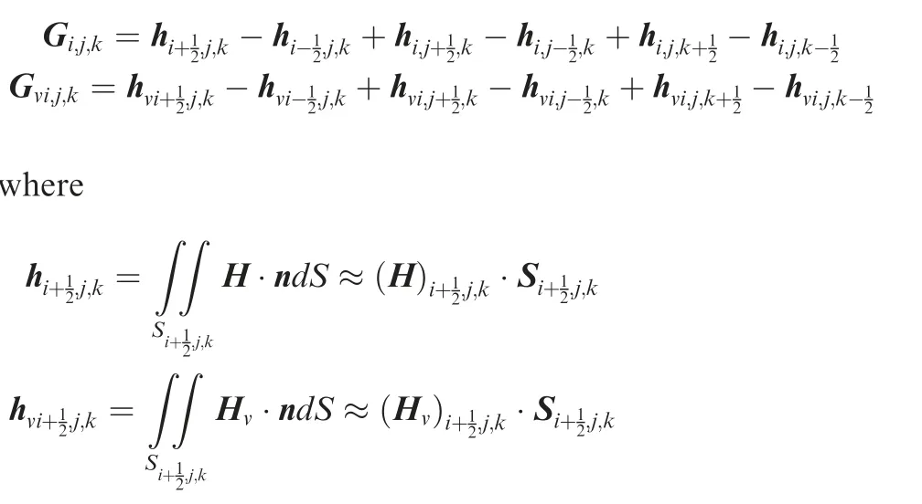
Ωis the volume of the cell(i,j,k).The minus sign‘-’and the plus sign ‘+’ represent the flux flowing in and out of the control volume through the oriented surface S. In the following,we will only consider the subscripts in the i direction for simplicity.
The viscous fluxes are discretized by the second-order central finite volume method, and the inviscid fluxes are approximated by the Roe flux difference splitting schemewhich features good robustness and high resolution.The Roe scheme at the cell interface i + 1/2,j,k can be briefly expressed as follows

where the subscript (L,R) stands for the left and right states across the cell interface. A, ρ, u, v, wand Hare evaluated by the formulas of Roe’s average. Harten’s entropy fixis used for avoiding non-physical solution.
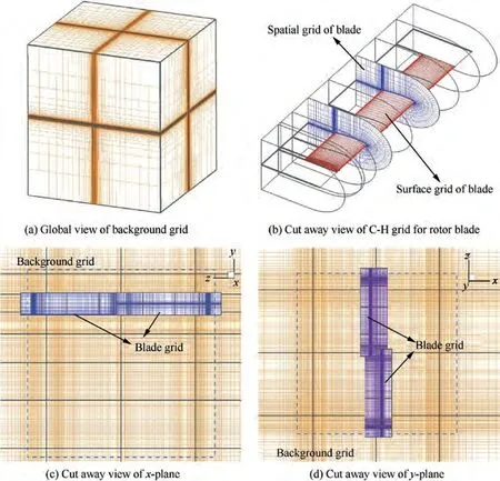
Fig. 9 Computational grid system of rotor in hover after partition.

Table 2 Partition of grid system for C-T rotor in hover.

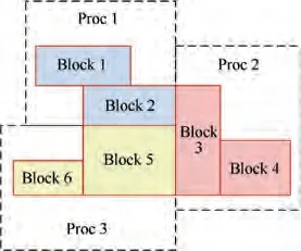
Fig. 10 Relationship between processors and grid blocks.
3.2.1. MUSCL scheme
The third-order MUSCL upwind-biased schemewith Van Albada limiteris expressed by
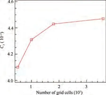
Fig. 11 CT of C-T rotor in hover vs total number of grid cells.

Table 3 Verification of grid convergence for C-T rotor in hover, Ma=0.439,θ=8°.
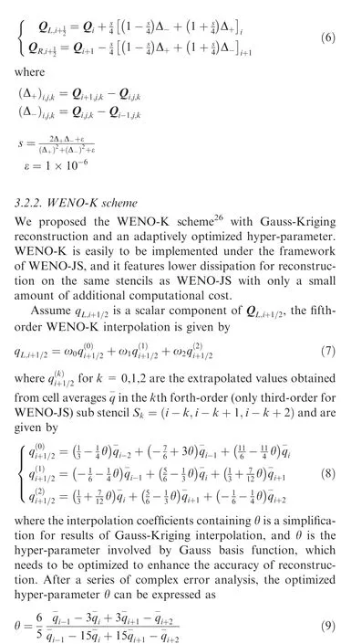
Table 4gives the pseudo codes for formulas of θ, by which one can obtain the value of θ efficiently with troubled cells eliminated automatically. The range of indicator a is determined by a large number of tests and works well for most cases.It is obviously that the WENO-K scheme degenerates to WENO-JS scheme when the value of θ equals zero.
Three three-cell stencils are combined with nonlinear weights ω(k = 0,1,2) to form a interpolation with higher
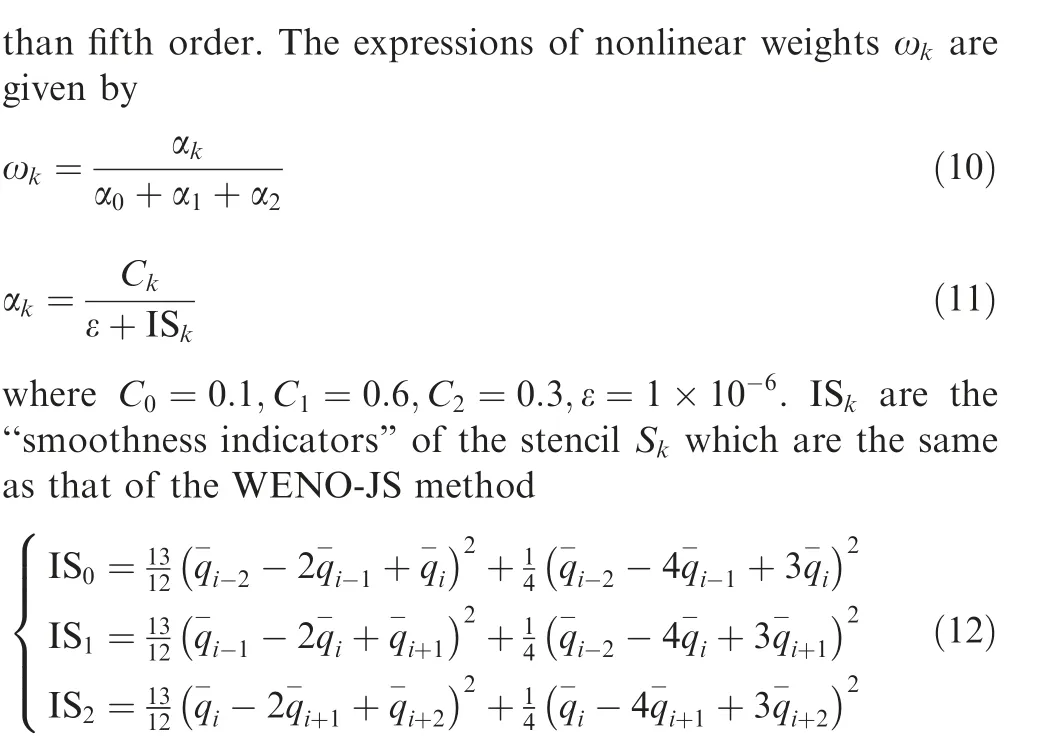
Fig. 12shows the modified wave number α of WENO-K scheme on three-cell stencils.We note that the dispersion properties of WENO-K scheme are comparably favorable to that of the WENO-JS scheme, and WENO-K scheme results in obviously lower dissipation over a substantial range of wave numbers.
The right value qcan be obtained by symmetry of the left and right states. After Cartesian coordinate system (x,y,z)is transformed to curvilinear coordinate system (ξ,η,ζ), spatial dimensions can be approximately decoupled and the reconstruction can be performed very efficiently dimension by dimension.
It should be emphasized that FVM can only reach secondorder accuracy especially for multi-dimensional flow field around complex boundaries. However, if the refined grid in wake region keeps nearly uniform and strictly orthogonal, an approximate high-order FVM can be obtained by performing high-order WENO reconstructions in the finite volume framework.The approximate high-order FVM features low dissipation, high resolution and high efficiency, which performs obviously better than MUSCL scheme for the capture of smooth flow structures and prediction of aerodynamic characteristics.
3.3. Temporal discretization
A full implicit dual-time stepping method with LU-SGS subiteration is adopted to advance the unsteady solution of the rotor flow in hover in time.Local time-stepping,implicit residual smoothing and multigrid method are applied to accelerate the convergence of sub-iterations.
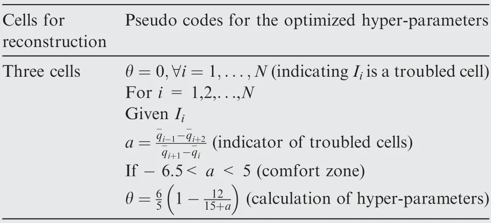
Table 4 Pseudo codes for the new formulas of optimized hyper-parameters.26.
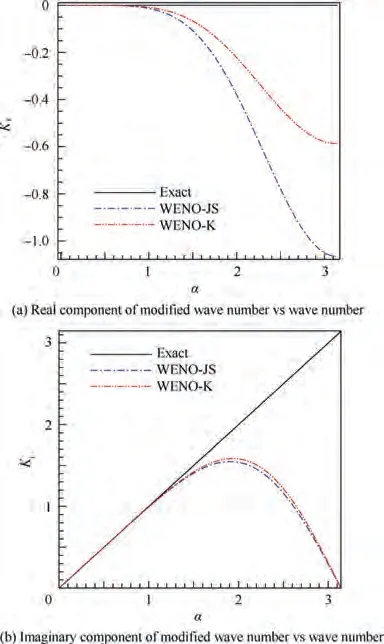
Fig.12 Dispersion and dissipation properties for WENO-JS and WENO-K scheme on three-cell stencils.26.
4. Results and discussion
The flow field of two-bladed C-T rotor in hover was simulated by using dynamic overset grid technique introduced in Section 2 and numerical method introduced in Section 3. The rotor blades are composed of NACA0012 airfoils and characterized by a rectangular platform with zero twist and an aspect ratio of 6. A comparative study was carried out by adopting the third-order MUSCL scheme,fifth-order WENO-JS scheme and WENO-K scheme respectively.
The computational cases for C-T rotor at two hovering conditions adopt the same overset grid system with a total number of 18,057,216 grid cells in the topology of 156 blocks.The overlap relation is generated in the single-block grid system as shown in Section 2.1,while the parallel simulation executed on the multi-block grid system after partitioned as shown in Section 2.4. The point is, interpolation information of overlap for the multi-block grid is exactly matched from the single-block grid system.
Unsteady RANS equations without any wake model are adopted to solve tip vortex. All simulations are carried out on TianHe-1(A) system of National Supercomputer Center in Tianjin.Each computing node is configured by 2 Intel Xeon CPUs(e5-2690 V4@2.60 GHz)with 14 cores,namely,28 processors per node. 10 revolutions of unsteady simulation are conducted and each revolution of rotation is divided into 360 physical time steps (Δψ=1) with 20 sub-iterations for each time step, which gives at least a third-order sub-iteration drop between time steps. 157 processors (156 sub-processors and 1 main processor) are used and the grid load of each sub-processor is about 115000,which strictly conforms to the load balance between processors and can maximize the efficiency of parallel computing.
Table 5 gives the comparison of wall-clock time spends by simulation of flow over C-T rotor in hover, and WENO-K scheme requires only 4.1% extra wall-clock time compared to WENO-JS scheme for every revolution.
4.1. Subsonic flows over C-T rotor in hover
The hovering rotor operates at the following condition: a tip Mach number Ma= 0.439, a pitch angle θ=8, a flapping angle β=0, a rotor shaft angle α=0and a Reynolds number Re = 1.92 × 10. Wake prediction is the key point of numerical simulation under this flow condition.
Table 6 shows that errors of Cbetween the computation and the experimentare less than 4%, and the WENO-K scheme even limits the error to a percentage less than 1%.The results of Cproves that the quality and quantity of the overset grid system adopted are sufficient, and the accuracy of the numerical method is also satisfactory. However, the high-accuracy prediction of aerodynamic forces for rotors is not the only advantage of the WENO-K scheme.
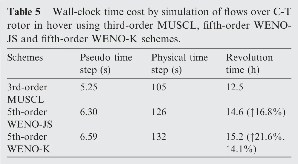
Fig. 13 shows the comparison of tip vortices visualized by iso-surface of q-criterion (q = 0.05) and contours of vorticity magnitude(interval from 0.4 to 0.8).It’s illustrated that the tip vortex is well captured at the wake age ψ=900°by WENO-K scheme, while ψ = 630° and ψ = 150° by the WENO-JS and MUSCL schemes respectively. Fig. 14 shows the comparison of vorticity contours on cutting planes along wake age, it can be seen that the strength of tip vortex captured by WENO-K is obviously higher than that of the other two schemes.
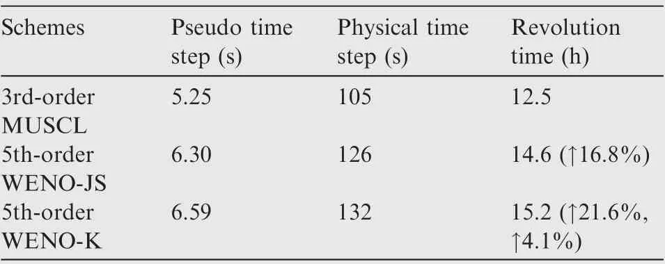
Table 5 Wall-clock time cost by simulation of flows over C-T rotor in hover using third-order MUSCL, fifth-order WENOJS and fifth-order WENO-K schemes.

Table 6 Comparison of thrust coefficients CT of C-T rotor in hoverbetweencomputationandexperiment,Ma=0.439,θ=8°.

Fig.13 Comparison of tip vortex for C-T rotor in hover(Vortices rendered with the iso-surface of q-criterion and contours of vorticity magnitude, Ma=0.439,θ=8°).
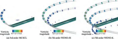
Fig. 14 Comparison of vorticity contours on cutting planes along wake age for C-T rotor in hover (Ma=0.439,θ=8°).
Fig. 15 shows the comparison of instantaneous vorticity contours on cutting planes parallel to chord and passing through rotor shaft, in which the tip vortices calculated by WENO schemes show obviously unsteady evolution, and the vortex sheets are clearly depicted by WENO-K scheme. The tip vortices generated by two blades interferes with each other when they develop to a certain wake age,and this evolution is called‘‘vortex pairing”.Vortex pairing between the upper and lower adjacent tip vortices is consistent with the experimental observation.The ‘‘vortex pairing” captured by WENO-K performs more remarkable than that of the WENO-JS, and the location (ψ=700° for WENO-JS, ψ = 930° for WENOK) where ‘‘vortex pairing” appears in the WENO-K case is closer to the published result(ψ=950°) that is simulated on a grid with a number of 100 million cells.
The computed pressure coefficient Cdistributions of blade cross sections by using the MUSCL,WENO-JS and WENO-K schemes are compared with the experimental data at r/R = 0.50, 0.68, 0.80 and 0.96 spanwise stations in Fig. 16.It can be seen that the numerical results of the three schemes are in well agreement with the experiment. Suction peaks calculated by fifth-order WENO schemes are closer to experimental results than third-order MUSCL scheme, and WENO-K scheme agrees obviously better with experiment than WENO-JS scheme at r/R = 0.80 and 0.96 spanwise stations.
All of the above analyses confirm that WENO-K scheme shows the highest accuracy and the lowest numerical dissipation among the three schemes.
4.2. Transonic flows over C-T rotor in hover
The hovering rotor operates at the following condition: a tip Mach number Ma= 0.877, a pitch angle θ=8, a flapping angle β=0, a rotor shaft angle α=0and a Reynolds number Re=3.93×10.This flow field features both smooth flow structures (vortices) and discontinuities (shock waves),therefore low dissipation and non-oscillation characteristics of numerical schemes can be examined simultaneously.

Fig. 15 Comparison of vorticity contours on cutting plane parallel to chord length and passing through shaft of rotor(Ma=0.439,θ=8°).
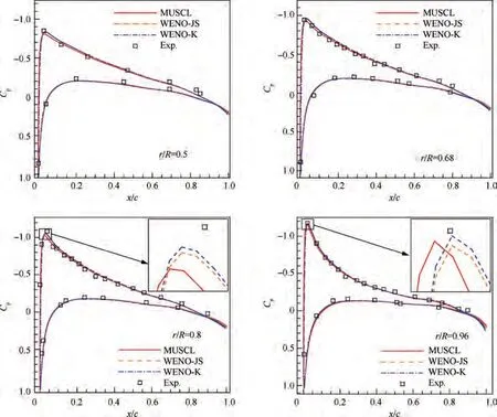
Fig. 16 Pressure coefficient distribution of blade cross sections as computed by MUSCL, WENO-JS and WENO-K schemes for C-T rotor in hover (Ma=0.439,θ=8°).

Table 7 Comparison of thrust coefficients CT of C-T rotor in hoverbetweencomputationandexperiment,Ma=0.877,θ=8°.
Table 7 shows that errors of Cbetween the computation and the experiment,and the WENO-K scheme still shows the best accuracy.Due to the existence of intensively nonlinear flow phenomenon (shock wave), the computational errors is relatively large but also accurate enough in the perspective of engineering application.

Fig.17 Comparison of tip vortex for C-T rotor in hover(Vortices rendered with the iso-surface of q-criterion and contours of vorticity magnitude, Ma=0.877,θ=8°).

Fig. 18 Comparison of vorticity contours on cutting planes along wake age for C-T rotor in hover (Ma=0.877,θ=8°).

Fig. 19 Comparison of vorticity contours on cutting plane parallel to chord length and passing through shaft of rotor(Ma=0.877,θ=8°).
Fig.17 shows the comparison of tip vortex rendered by isosurface of q-criterion(q=0.25)and contours of vorticity magnitude (interval from 0.9 to 2). The tip vortex is well captured at the wake age ψ = 1000° by using WENO-K scheme, while ψ = 720° and ψ = 250° by using WENO-JS and MUSCL schemes respectively.Fig.18 shows the comparison of vorticity contours on cutting planes along wake age, and again, the tip vortex captured by WENO-K is obviously stronger than the other two schemes.
Fig.19 shows the comparison of vorticity contours on cutting plane parallel to chord and passing through the shaft of the rotor. The wake structure of tip vortices and vortex sheets captured by WENO schemes are very clear. No ‘‘vortex pairing” is observed within the visible revolution, because the tip vortices at the condition of Ma=0.877 and θ=8is stronger and go down faster to keep it on track. However, the tip vortices calculated by WENO-K scheme still shows obviously unsteady evolution.
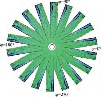
Fig. 20 Pressure distribution on the blade at different azimuth angles for C-T rotor in hover (Ma=0.877,θ=8°).
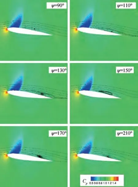
Fig. 21 Streamlines on chordwise profile at 95%R of the blade for C-T rotor in hover (Ma=0.877,θ=8°).
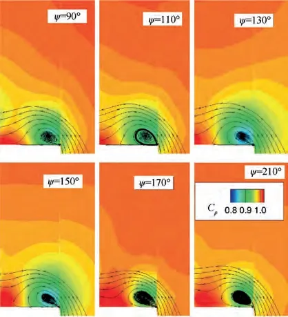
Fig.22 Streamlines on spanwise profile at 75%c for C-T rotor in hover (Ma=0.877,θ=8°).
Here we focus on the phenomenon that the simulated tip vortex is not smooth enough as shown in Fig. 17. For the numerical simulation of flow over a single rotor in hover,most researchers use the quasi-steady method or the unsteady method with very sparse grid. The consequence is that some unsteady flow phenomena is smoothed out, and the iso-surface of tip vortices look very regular and smooth,which is not actually consistent with the reality.Some published studies about unsteady simulation of rotors in hover on highly fine grid have proved that the unsmooth tip vortex can be visualized in the high-accurate numerical simulation.
The pressure distribution at the blade tip show slight differences at different azimuths as shown in Fig.20.Fig.21 directly illustrates that there exist strong shock wave and unsteady separation flow near the blade tip, and the shape, strength, and position of the separation vortex change with time. Furthermore, Fig. 22 shows that the unsteady separated flow near the blade tip attaches a direct effect on the strength and position of the tip vortex.As a result,the strength and the position of the vortex core generated at different azimuth angles are slightly different,and this difference can be gradually enlarged during downward development of tip vortex, which resulting in an unsmooth iso-surface as shown in Fig. 17.
The pressure coefficient distributions of blade cross sections as computed by the MUSCL, WENO-JS and WENO-K schemes are compared with the experimental data in Fig. 23.The numerical results of the three schemes coincide well with the experiment.The suction side at r/R=0.80 and 0.96 spanwise stations calculated by fifth-order WENO schemes shows a sharp shock profile.The main advantage of WENO-K scheme is reducing numerical dissipation while maintaining discontinuity capture ability of WENO-JS scheme, therefore WENO-K performs only slightly better than WENO-JS for shock wave capture.
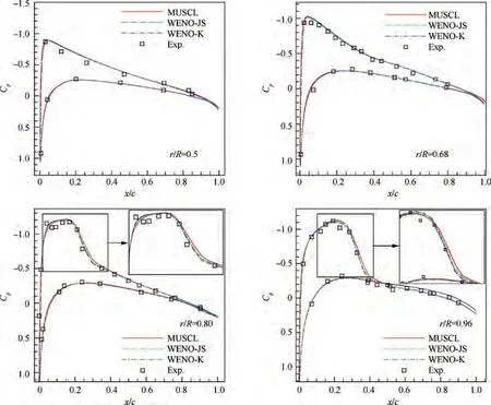
Fig.23 Pressure coefficient distribution of blade cross sections as computed by the MUSCL,WENO-JS and WENO-K schemes for C-T rotor in hover (Ma=0.877,θ=8°).
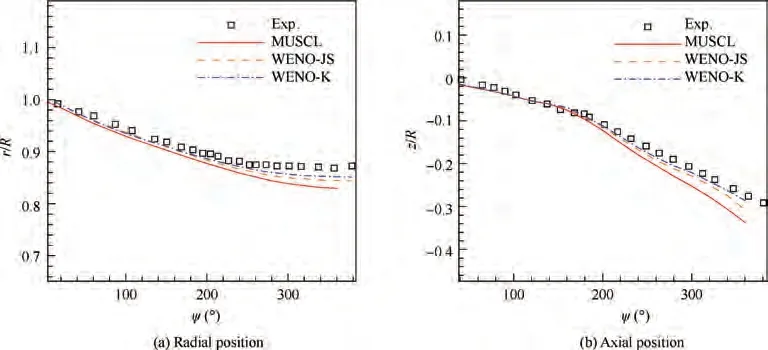
Fig. 24 Trajectory of core of tip vortex along with wake age (Ma=0.877,θ=8°).
The radial position of the tip vortex core mainly reflects the contraction of rotor wake while the axial position of tip vortex core mainly reflects its downward development. As shown in Fig. 24, the tip vortex shrinks faster along the radial direction before 200° wake age and downward motion of tip vortex along the axial direction is accelerated after 180° wake age.These evolutions of tip vortex predicted by all the schemes are basically consistent with the experimental results.Benefit from excellent capacity of vortex preservation due to lowest numerical dissipation, the trajectory of tip vortex captured by WENO-K scheme matches best with the experiment along circumferential direction after ψ = 200° and axial direction after ψ = 180° among the three schemes. Compared with the published resultsthat used URANS method without wake models,the results in this work are satisfactory especially for the result of WENO-K scheme. When the grid is further refined, the prediction accuracy of tip vortex trajectory can be further improved.
5. Conclusions
(1) The high-order WENO-K scheme that achieves innovative reconstruction utilizing the Gauss-kriging interpolation with an optimized hyper-parameter is extended to discretize URANS equations for complex flow dominated by unsteady vortices for the first time.
(2) A multi-start distance decreasing method is proposed to accelerate the update of overset relationship and a method of multilayer fringes are presented to support high-order flux-reconstruction on artificial boundaries.
(3) A massively parallelizable simulation method features high-order accuracy and low dissipation for unsteady vortex flows over rotors in hover is established based on WENO-K scheme and an averagely partitioned dynamic overset grid system.
(4) The results demonstrate that the WENO-K scheme can effectively preserve vortex wake to a larger wake age with a more accurate trajectory of vortex core,and capture more sophisticated unsteady vortex structures with higher resolution for discontinuities than WENO-JS scheme. In addition, the WENO-K scheme only spend 4.1% extra computational cost compared to WENOJS scheme.
In our current work,we implemented the WENO-K scheme to the flow simulation for rotors in hover. In our future research,we will investigate the WENO-K scheme on the flow simulation for rotors in forward flight or even the coaxial rotors and a whole helicopter.Besides,it would be an interesting research to transplant the innovative reconstruction of WENO-K to other variants of WENO schemes (such as WENO-Z) to enhance their accuracy and apply these schemes to simulations for flows over rotors.Furthermore,we will also investigate the influences of aerodynamic shape on tip vortex.
The authors declare that they have no known competing financial interests or personal relationships that could have appeared to influence the work reported in this paper.
This study was co-supported by the National Natural Science Foundation of China (No. 12072285) and Shaanxi Science foundation for Distinguished Young Scholars, China(No.2020JC-13).The authors would like to thank the National Supercomputer Center in Tianjin for their computational resource of TianHe-1(A).
 Chinese Journal of Aeronautics2022年5期
- Chinese Journal of Aeronautics的其它文章
- Multiframe weak target track-before-detect based on pseudo-spectrum in mixed coordinates
- Mahalanobis distance-based fading cubature Kalman filter with augmented mechanism for hypersonic vehicle INS/CNS autonomous integration
- A new target tracking filter based on deep learning
- Structure-aware fusion network for 3D scene understanding
- A novel combination belief rule base model for mechanical equipment fault diagnosis
- De-combination of belief function based on optimization
