Effects of traverse speed on weld formation,microstructure and mechanical properties of ZK60 Mg alloy joint by bobbin tool friction stir welding
Gohui LI, Li ZHOU,,*, Hifeng ZHANG, Snfeng LUO, Ning GUO
a State Key Laboratory of Advanced Welding and Joining, Harbin Institute of Technology, Harbin 150001, China
b Shandong Provincial Key Laboratory of Special Welding Technology, Harbin Institute of Technology (Weihai), Weihai 264209, China
KEYWORDS Bobbin tool;Friction stir welding (FSW);Magnesium alloys;Mechanical properties;Microstructure evolution;Traverse speed
Abstract ZK60B(Mg-6%Zn-0.6%Zr)alloy joints fabricated by bobbin tool friction stir welding(BTFSW)with various traverse speeds were investigated.The sound joint fabricated by the BTFSW was possible under the appropriate welding parameters. The severe plastic deformation during BTFSW resulted in dispersion and segregation of the Zr-rich particles within the stirred zone(SZ)followed by evolution of a bimodal grain structure with distributed bands of 0.8-1.7 μm ultrafine grains and 4.1-7.1 μm equiaxed grains. Micro-hardness of SZ is substantially reduced in contrast to that of parent metal (PM) in spite of the finer grain size owing to dissolution of Mg-Zn based precipitates having hardening effects on alpha-Mg matrix. With the decrease in traverse speed,randomization degree of the plasticized metal flow increases, which is evidenced by the randomized arc line pattern at the low traverse speed. Among all defect-free joints, the 200 mm/min joint exhibits the weakest isotropy of texture within SZ and the best tensile properties, which has reduced ultimate tensile strength and yield strength by 5.4% and by 22.2%, respectively, as compared to the PM.The randomized texture hinders the joint fracturing within SZ at low elongation.Therefore, a relatively high elongation of 10.8% was achieved, which corresponded to 72% of the PM value.
1. Introduction
Among all metallic structural materials,Mg alloy is the lightest and has extensive potential for such applications in the aeronautics, automobile as well as railway industries.1Generally,Mg alloys are superior in specific rigidity, specific strength,damping capacity and recyclability.2However, due to the hexagonal close packed (HCP) crystallographic structure with limited number of independent slip systems, Mg alloys are inferior in formability as well as ductility.3Therefore, the majority of the Mg alloy products were produced by casting,and there were few Mg alloy products being fabricated by plastic forming and welding, which has limited the industrial application of Mg alloys.4In order to widen its applications, development of an appropriate welding process is imperative.
FSW,being a newly developed solid state joining technique with the welding process performed below the melting point of the PM,solves the problems of porosity and large distortion of the weld associated with conventional fusion welding of Mg alloys.5FSW is a thermo-mechanical process which imparts local plastic deformation with extremely high strain rate in the SZ and produces a preferable microstructure with fine equiaxed grains.6,7For the fine-grained material, FSW is a preferable welding method because of the inhibited grain growth resulted from the lower welding temperature of the process.8,9On the other hand, the plasticized metal flow induced by the rotating tool causes lattice reorientation for individual grain in polycrystalline materials, so that crystallographic textures tend to evolve.10For the Mg alloys,crystallographic textures exhibiting highly concentrated grain orientations are evolved in the SZ of FSW joint.11The orientation component of the crystallographic texture in the SZ varies significantly in different positions, resulting in severe anisotropy of plastic deformation under uniaxial transverse tensile loading and preferential fracture in the zone with specific grain orientations.12Therefore, achieving the randomization of the strong crystallographic texture is imperative to the reversion of the FSW.
One of the possible methods to achieve this reversion is the employment of a bobbin tool which simultaneously stirs the workpieces on the both sides,13as shown in Fig. 1(a). Compared to the conventional FSW,a more heat input is produced during the BTFSW owing to the combination use of two shoulders, which then affects the readiness of the plasticized metal to flow.14Moreover, as the bobbin tool exerts deformation on the workpieces from the both sides,a more severe and complex plastic deformation can be imparted in the joint than that in the conventional FSW.15The variations in plastic deformation and heat input between conventional FSW and BTFSW enable BTFSW to provide more complex plasticized metal flows in SZ followed by evolution of randomized crystallographic textures. Furthermore, as the bobbin tool generates heat as well as drives plasticized metal flows during BTFSW process,geometry of bobbin tool is one of the most significant factors affecting the joint quality.16It is predictable that the complicated bobbin tool geometry, e.g., the attachment of the scrolled,flat and tapered part,provides more complex plasticized metal flows followed by an additional weakening of the crystallographic textures.
Previous investigations on BTFSW of Mg alloy significantly concentrated on investigating effects of processing parameters on mechanical behaviors of the joints.17,18while the crystallographic texture evolutions in Mg alloy occasioned by BTFSW have yet to be revealed.Therefore,the aims of the present research are to clarify the crystallographic texture evolutions induced by BTFSW with the specifically designed bobbin tool as schematically shown in Fig. 1b for the ZK60 Mg alloy as well as investigate the effects of traverse speed on the joints.
2.Experimental setup microstructure and mechanical properties of the
ZK60B Mg alloy extruded sheets were employed as PM,whose experimental tensile properties along with chemical compositions were summarized in Table. 1. Dimensions of the sheets are 4 mm thick, 100 mm wide and 300 mm long. The sheets were butt-welded along extruding direction (coincides with longitudinal direction)by using a displacement controlled type gantry FSW machine.Welding trials were carried out at a constant rotational rate of 700 r/min for the bobbin tool over a range of traverse speeds from 150 to 400 mm/min. The schematic illustration for the bobbin tool is shown in Fig. 1b.The bobbin tool consisted of a tapered stir pin with three flats feature and two flat shoulders with scrolled feature. The scrolled channel on the surface of the shoulder can capture plasticized metal at the shoulder edge and feed it inwards to the weld zone.19The three flats feature on the tapered pin can promote horizontal motions of the material around stir pin which is of great importance for weld formation.20The ratio of shoulder plunge depth to sheet thickness (namely the compression ratio) was selected as 0.03. Previous investigations21,22reported that such a compression ratio can stably preserve the plasticized metal within the weld zone for plate thickness less than 8 mm. 3D surface analyses of the BTFSW joints were carried out by employing a 3D surface analysis system (Olympus DSX 510). Microstructure characterizations were performed on the cross section plane paralleling to both the transverse direction (TD) and normal direction (ND).Metallographic samples were mechanical grinded with emery papers to 3000 grit, polished with 0.5 μm alumina powder and then chemically etched with acetic picral (4 mL distilled water, 10 mL ethanol, 2 mL acetic acid and 0.2 g picric acid).The electronic backscattering diffraction (EBSD) technique was employed to evaluate texture developments of ZK60 Mg alloy after BTFSW, and EBSD data was analyzed by the TSL OIM analysis 7 program.The specimens for EBSD examination were prepared by the same mechanical polishing procedure as the metallographic sample,then electro-polished with a solution consisted of 60 ml ethanol and 30 ml phosphoric acid under 15°C at 0.25 A for 7 min.Scan step size was selected as 0.7-1.0 μm.Confidential index for the EBSD orientation color map lay in the range of 0.3-0.45. Micro-hardness distribution across the weld zone was measured by a computerized Vickers micro-hardness tester operated at a 300 g load with a 13 s dwell time. The 2D micro-hardness maps were consisted of seven lines of indentations on the cross sections with indentation space of 0.5 mm and line space of 0.5 mm, as schematically illustrated in Fig. 1c. Transverse tensile test of the BTFSW joint was performed in air at room temperature using an Instron 5976 tensile tester at a crosshead displacement speed of 0.3 mm/min. The transverse tensile samples were dog bone in shape, which had the dimensions presented in Fig. 1d.The transverse tensile samples were prepared based on China National Standard GB/T2651-2008, and the tensile properties of each joint were evaluated by three tensile samples sectioned from the same joint.
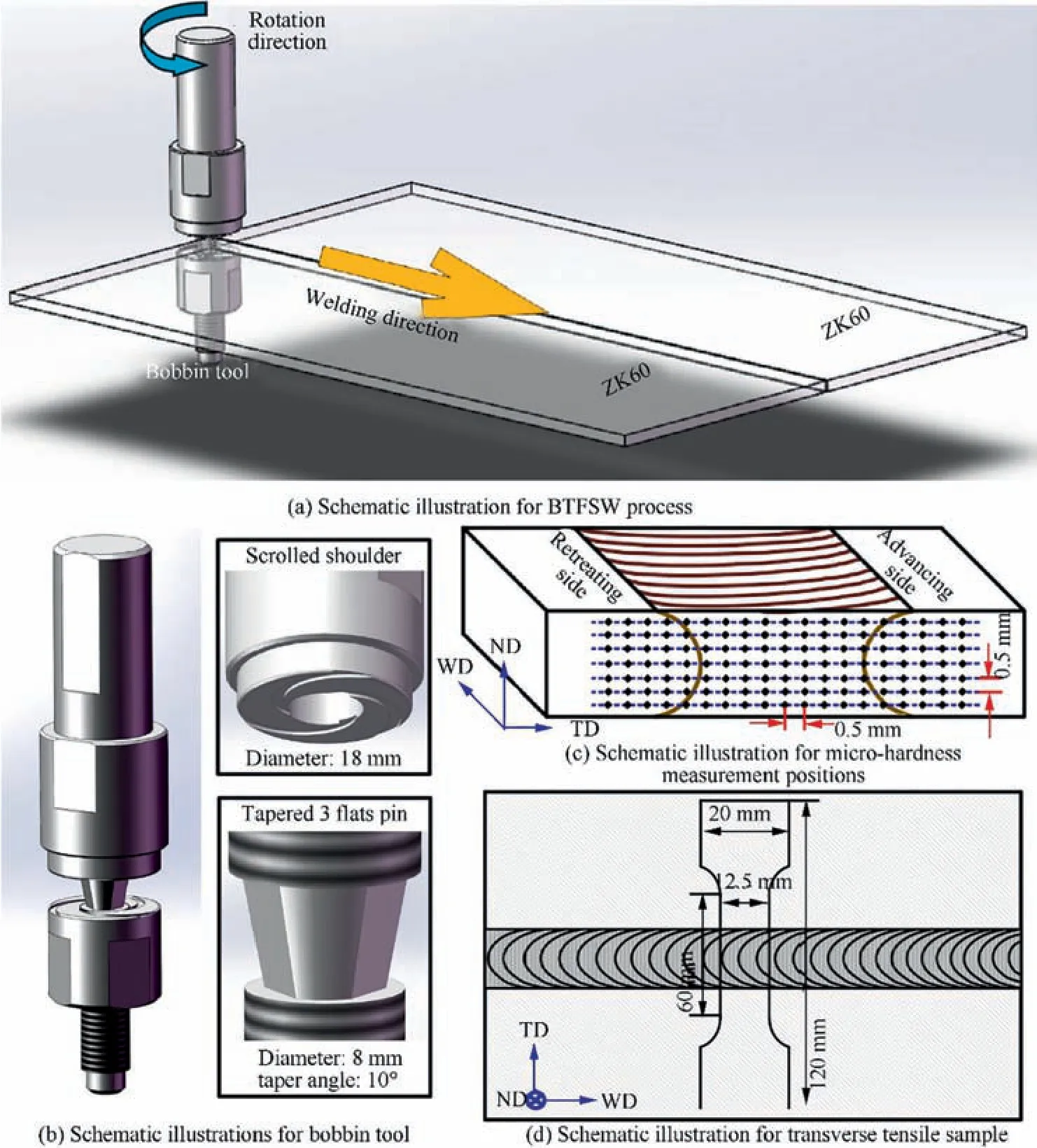
Fig.1 Schematic illustrations for welding process,BTFSW tool,micro-hardness measurement positions and transverse tensile specimen.

Table 1 Experimental tensile properties and chemical compositions of the ZK60.
3. Results and discussions
3.1. Weld formation and microstructure characterization
As bobbin tool stirs sheets on the both sides, arc lines are formed on both lower and upper surfaces of the BTFSW joint and exhibit a similar distribution. Therefore, only the upper surface arc line behaviors were selected for 3D surface analysis.Fig.2 illustrates the 3D morphologies for upper surfaces of all the BTFSW joints with traverse speed varying from 150 to 400 mm/min. It is noted that with an increase in the traverse speed, interval between neighboring arc lines increase and the number of arc lines decrease. This phenomenon can be explained by the following law.23For conventional FSW and BTFSW, the average interval i between neighboring arc lines can be estimated through

where ω denotes the tool rotational speed which is 700 r/min in the present investigation, while ν denotes the traverse speed.Moreover, linear analysis was conducted along weld centerline paralleling to welding direction(WD)to determine heights and curvatures of the arc lines.It reveals that with the increasing traverse speed, not only the interval between neighboring arc lines, but also the curvatures and heights of the arc lines change simultaneously. Three kinds of arc line behaviors are discerned. In the case having 150 or 400 mm/min traverse speeds,all the arc lines exhibit the same height,and the curvatures of the arc lines vary periodically.The arc line curves measured at traverse speeds of 150 and 400 mm/min can be approximately fitted by the sine curves of
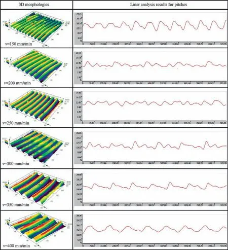
Fig. 2 3D morphologies for upper surfaces of BTFSW joints with traverse speed varying from 150 to 400 mm/min.

respectively. Where x represents the abscissa value for the point,y represents the ordinate value for the point,and π represents the circular constant.When the traverse speed is set as 300 or 350 mm/min, some arc lines exhibit a lower height as compared to the others. Moreover, it can be found that the curvatures of the arc lines change periodically with a periodical length equal to the interval between three arc lines. However,the arc lines show more random patterns at traverse speeds of 200 and 250 mm/min. Generally, formation of arc lines is considered as a result of the discontinuous forging effect from both the top and bottom shoulders during the BTFSW and is closely related to the plasticized metal flow regime within the SZ.13Therefore, the randomized patterns of the arc lines at the 200 and 250 mm/min traverse speeds may indicate more complicated patterns of plasticized metal flow during the welding process.

Fig. 3 Cross-sectional macrostructures for BTFSW joints obtained at different traverse speeds.
Fig. 3 presents the macrographs of cross sections of the joints obtained under various traverse speeds on the ZK60 Mg alloy. The retreating side (RS) and advancing side (AS)is located on the right and left, respectively. Optical micrographs indicate that the cross sectional macrostructures of the joints are vertically symmetrical,as a result of the balanced deformations and heat generation induced by bobbin tool.Three distinctive microstructural zones, i.e., the PM, SZ and transition zone (TZ) are identified. Among all the welding parameters,sound joints are achieved at traverse speeds above 150 mm/min but below 400 mm/min. Concerning the joint produced at a traverse speed of 150 mm/min, an internal tunnel defect along with plenty of tiny cavities can be observed in the SZ. Similar result has been reported by Li, et al.18in the BTFSW of AZ31A Mg alloy, and the authors indicated that excess heat input under the low traverse speed could lead to the unbalance mass flux which generated the tunnel defect.Increasing traverse speed can enhance backward pumping of plasticized metal into the region on the AS in which the tunnel defects readily occur.24Consequently, the BTFSW joints free of tunnel defect can be obtained at the higher traverse speeds.Additionally, for joint fabricated at traverse speed of 400 mm/min,a long crack in the SZ center penetrating roughly half of the joint’s thickness can be discerned.It is deduced that heat input under the traverse speed of 400 mm/min is insufficient to get the metal within the weld zone into a fully plasticized state, thereby lack of bonding at the initial butt interface.
Fig. 4 presents typical microstructures of various zones of the BTFSW joint.The locations selected for the microstructure characterizations are indicated in the cross-section macrostructure at the top.Locations selected for the microstructure characterization are indicated in the cross-sectional macrostructure at the top. Fig. 4(a) shows that the PM has a bimodal grain structure characterized by coarse island-shaped grains mingled with distributed bands of finer partially recrystallized grains,which is consistent with the typical grain structure of asextruded ZK60 Mg alloy.3Grain structure of TZ is shown in Fig. 4(b)-(d). The TZ is featured by finer grains than that of the PM, and it appears that the grain structure is compressed and bended due to plastic deformations occasioned by the bobbin tool (see Fig. 4(b) and (c)). From a magnified optical image, i.e., Fig. 4d, it can be figure out that the TZ contains highly elongated grains and fine equiaxed grains. Generation of the fine equiaxed grains implies that dynamic recrystallization has occurred within this region. However, the dynamic recrystallization experienced within the TZ is incomplete owing to the inadequate thermal exposure and deformation strain.25. As presented in Fig. 4(e)-(g), fine equiaxed grains are evolved in the whole part of the SZ, indicating the occurrence of completely dynamic recrystallization as a result of combination of severe strain and thermal exposure.Moreover,grains in SZ on the AS (~5.4 μm, in Fig. 4(e)) are finer than those on the RS (~7.1 μm, in Fig. 4(g)). This result is consistent with the phenomenon observed by Forcellese, et al.26in the conventional FSW of AZ31 Mg alloy. The main reason for the finer grains on the AS is that the AS possesses higher strain rate as compared to the RS as the tool displacement and rotation are in the same direction on the AS. A previous investigation27indicated that the AS also possesses a faster nucleation rate as well as a more extensive dynamic recrystallization. Fig. 4(h) presents the microstructure near upper surface of the joint. Distributed bands of 0.8-1.7 μm ultrafine grains are observed in this region.The corresponding scanning electron microscopy(SEM)image(Fig.4(i))indicates the existence of a large number of fine second phase particles being distributed between the ultrafine grains. It is postulated that these intermetallic particles have strong pinning effects on grain boundary migration which leads to the inhibition of grain growth after the dynamic recrystallization.
In order to get deeper insights into the evolution of the ultrafine grains. An energy dispersive X-ray spectroscopy(EDS) elemental mapping of the region containing ultrafine grains was conducted. Fig. 5 presents the backscattered electron image (a) as well as corresponding EDS elemental maps of Mg (Fig. 5(b)), Zn (Fig. 5(c)) and Zr (Fig. 5(d)). The EDS map(Fig.5(d))indicates that the distributed bands of ultrafine grains are enrichment of zirconium while the adjacent coarser grains are with smaller amount of zirconium element, indicating the fine particles observed in Fig.4(i)are Zr-rich particles.The previous investigations28,29have documented that Zr-rich precipitates acted as a significant role in grain refinement of ZK60. Plasticized metal next to weld surfaces is believed to be exposed to the most intense thermal effect during welding,because the majority of the frictional heat is produced at workpiece/shoulder interfaces.30On the other hand, plasticized metal in this region also experience larger shear force from the shoulder because it is directly in contact with the shoulder.The combination of severe frictional heating and intense plastic deformation in this region may lead to dissolving, dispersing or segregation of the Zr-rich particles followed by evolution of the distributed bands of ultrafine grains.Element segregation occurs readily during thermo-mechanical process owing to the accelerated diffusion kinetics under the elevated temperature as well as the large number of microstructural defects introduced during the plastic deformation which provided an easier path for atomic migration.31Segregation of Zr element which lead to generation of a bimodal grain structure having 5-10 μm fragmented coarse grains and ~1 μm fine equiaxed grains was also reported in the friction stir processed ZK60A Mg alloy by Mansoor and Ghosh.3
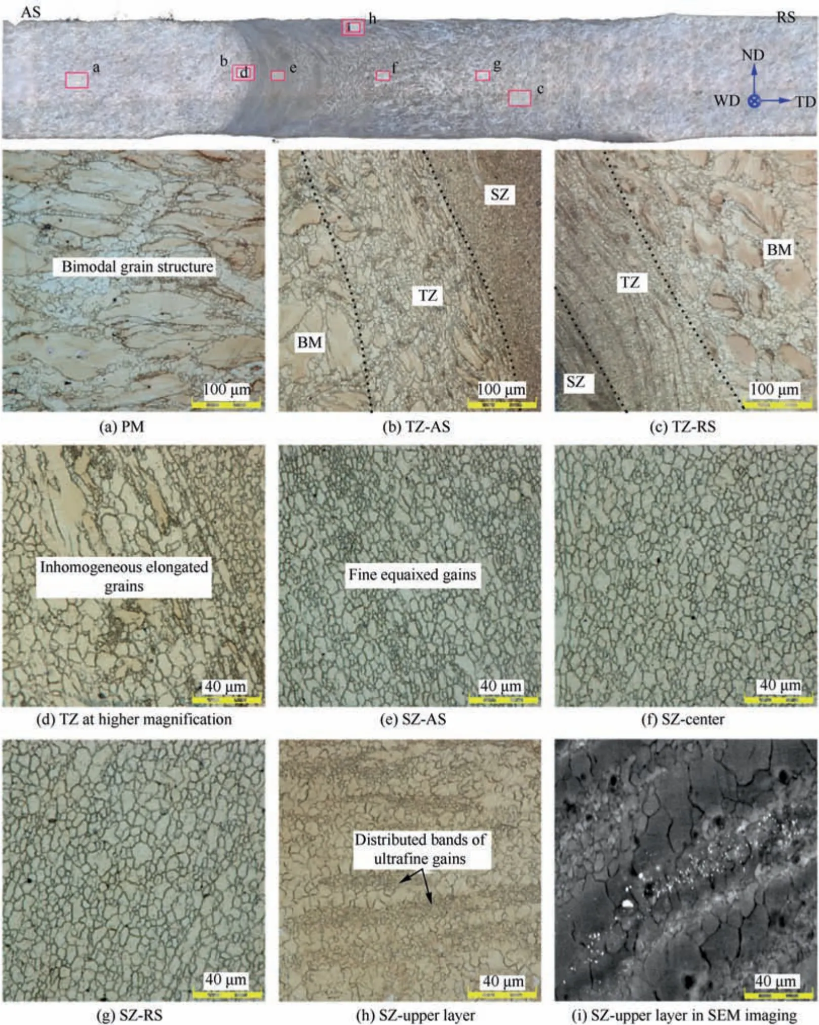
Fig. 4 Grain structure in various regions of a BTFSW joint.
Zk60 is a precipitation strengthened Mg alloy, therefore,investigating the precipitation evolution during BTFSW is of great importance. Fig. 6 presents the SEM images of PM as well as SZ. The SEM image of the PM (Fig. 6(a)) show the presence of plenty of fine precipitates mainly distributed along grain boundaries. EDS analysis in Fig. 6b indicates that these precipitates consist of Mg and Zn elements. This is similar observation to a previous investigation by Yang, et al.,32who comprehensively analyzed the precipitates in ZK60 Mg alloy and indicated that thephase with a chemical composition of Mg4Zn7is the main precipitate in ZK60 Mg alloy.In the TZ,some precipitates mainly precipitated along the boundaries of the elongated grains are observed (Fig. 6(c)), whereas the distribution density of the precipitates significantly decreases in contrast to that of the PM microstructure,indicating the occurrence of precipitates dissolution. Similar to the TZ, the distribution density of precipitates in the SZ is also strongly reduced due to the severe thermal exposure (Fig. 6(d)).Dissolution of precipitates in TZ and SZ will lead to softening in the two regions so that affect BTFSW joint’s fracture.
3.2. Microstructure and texture inhomogeneity
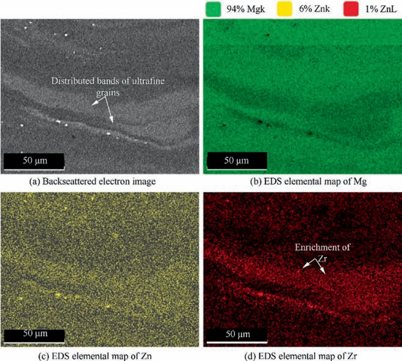
Fig. 5 EDS/SEM elemental mapping of region containing distributed bands of ultrafine grains.
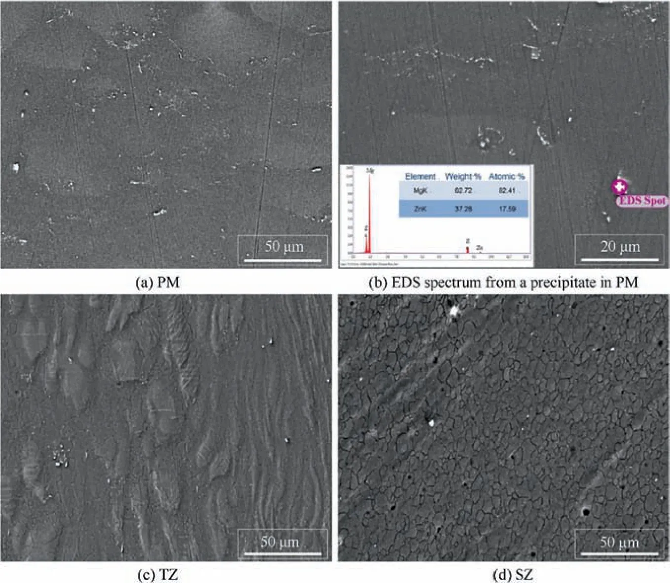
Fig. 6 SEM images illustrating precipitates distributions in different regions of a BTFSW joint.
Texture evolution has been an important issue for FSW/FSP of Mg alloy since it significantly affects tensile behaviors of the joint.Fig.7 presents orientation color maps(OIM)in various sub-regions along transverse centerline(i.e.,the AS-i,ASii, SZ-C, RS-i and RS-ii) of the BTFSW joint. The locations selected for the EBSD examination are indicated in sketch map located in the top. These OIMs exhibit various color schemes at the various positions, indicating that the grain orientation changes with the different measurement positions.At the traverse speed of 200 mm/min, the OIMs obtained at all the five regions show relatively complicated color schemes with a mixing of several colors suggesting a relatively randomized grain orientation. With increase of traverse speed from 200 to 350 mm/min,a color scheme simplification can be identified in the OIMs of AS-iiand SZ-C. The OIM of AS-ii at the traverse speed of 350 mm/min shows red color dominantly, indicating highly concentrated <0001> grain orientations in this region.Different plasticized metal flow leads to different grain orientation evolution in the SZ15.Therefore,the simplification in color scheme with the increasing traverse speed may be associated with the lowered heat input and the decreased complication degree of plasticized metal flows. However, no obvious variation in color scheme with increase in traverse speed can be detected in OIMs of RS-i and RS-ii, which indicates that the plasticized metal flow on the RS is less likely to be affected.
Grain size distributions as evaluated by the EBSD technique of the five selected regions are plotted in Fig.8.Average grain sizes in SZ on AS are lower than those on RS.This result is in line with the observations by optical microscopy. Moreover,the average grain sizes in all the five regions decrease with the increasing traverse speed as a smaller heat input is generated at the higher traverse speed. In the double-sided FSW of AZX612 Mg alloy, no significant grain size variation is detected with the change in heat input,23which is different from the present result. In the microstructure of the AZX612 Mg alloy, plenty of Al2Ca precipitates were detected. It was postulated that the homogeneously distributed Al2Ca precipitates inhibited the grains from growing while its distribution density was not significantly affected by the double-sided FSW process as the welding temperature was much lower than the dissolution temperature of Al2Ca. Mg4Zn7precipitates in ZK60 possess a much lower melting point than Al2Ca, and its distribution density is significantly reduced within the SZ(see Fig. 6). Therefore, the relatively significant variation in grain size with the changing heat input is also reasonable.
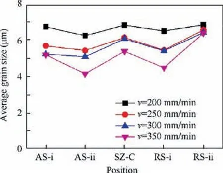
Fig. 8 Average grain sizes in various regions along transverse centerline of joint at various traverse speeds.
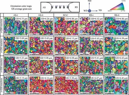
Fig. 7 Orientation color maps of the various regions along transverse centerline of the BTFSW joint.
Fig. 9 presents the {0001} pole figures obtained from various regions along transverse centerline for each BTFSW joint with the locations selected for the EBSD examination schematically indicated at the top. The {0001} pole figures show that the texture changes with the various measurement positions.Specifically, the positions of the SZ-C and AS-ii of the 200 mm/min joint show basal textures with the<0001>crystal orientation mainly aligning parallel and approximately 45 to the WD, respectively. It appears that the <0001> crystal orientations are roughly aligned perpendicular to side surface of stir pin in these two positions, and this tendency is caused by activations of basal slip systems under shear stresses of rotating stir pin.11On the other hand,the RS-ii position shows a relatively strong basal texture with<0001>crystal orientation roughly aligning parallel with ND. Formation of this<0001>||ND texture component was associated with the compression stress of the shoulders.15With traverse speed increases from 200 to 350 mm/min, the texture components presented in the {0001} pole figures of SZ-C and AS-ii positions become progressively strong and are characterized by higher concentrating. This corresponds to the color scheme simplification with the increasing traverse speed in OIMs of these two positions. Less types of grain orientations within the same region upper the texture intensity. It can be deduced that with the increasing traverse speed, stirring effect imposed on the plasticized metal within the SZ by the bobbin tool gets weakened,thereby resulting in plasticized metal flows in SZ on the AS (which is more readily to be affected) into a relatively simple pattern followed by evolution of a stronger texture.
The highest intensity of {0001} texture as measured by the EBSD technique in the various regions along the transverse centerline is plotted in Fig. 10. Among all the welding parameters,the BTFSW joints fabricated at the 200 and 250 mm/min traverse speeds show weaker isotropy of{0001}texture within the SZ which leads to improved tensile behaviors (especially yield strength (YS) and elongation (EI)). This point of view is backed by the tensile test results shown in the following section where BTFSW joints fabricated at the 200 and 250 mm/min traverse speeds exhibit relatively superior tensile properties. It is inferred that with the increasing traverse speed, the complication degree of plasticized metal flow within the SZ during the BTFSW process decreases, consequently, resulting in evolution of strong basal textures and corresponding deteriorated tensile properties.
3.3. Mechanical behaviors of the BTFSW joint
Fig. 11(a) presents micro-hardness maps in ND-TD plane through joints at the various traverse speeds. It is evident that the micro-hardness distributions are nearly symmetrical about TD,as a result of homogeneous deformation and temperature distribution along ND induced by the bobbin tool.The microhardness values of PM scattered between 71 and 75 HV.Micro-hardness values within the weld zone fluctuate between 61 and 70 HV, which is distinctly lower than that of the PM.This result agrees with the findings in conventional FSWed ZK60 Mg alloy joints.28The variation in micro-hardness is mainly related to type and distribution density of fine precipitates and grain size variation.4Grains in SZ are significantly refined in contrast to PM, which is in favor of upper the micro-hardness value with reference to the Hall-Petch relationship.1Nevertheless, previous investigation indicated that precipitation strengthening effect on micro-hardness was dominate for ZK60 as Mg-Zn based β′1 precipitates prevail in ZK60 exerted strong hardening effects on alpha-Mg matrix.32The precipitation reaction for ZK60 Mg alloy is generally considered to occur in the following sequence29,32:
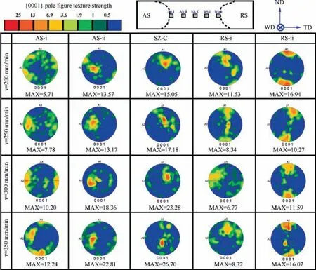
Fig. 9 {0001} pole figures obtained from various regions along transverse centerline of joint.
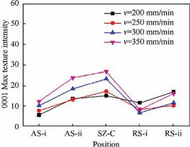
Fig. 10 Texture intensities in various regions along transverse centerline of joint at various traverse speeds.
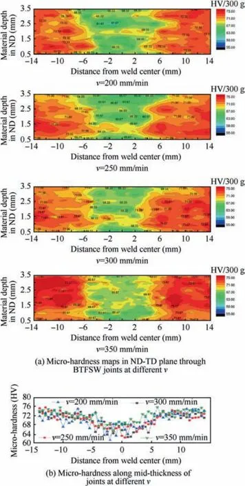
Fig. 11 Micro-hardness distributions through BTFSW joints at various traverse speeds.
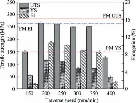
Fig. 12 Tensile test results for BTFSW joints and PM.
α(supersaturated solid solution)→Mg-Zn co-clusters →β′1(Mg4Zn7, [0001]Mgrod, coherent with the matrix)→β′2(MgZn2, (0001)Mgplate, semi-coherent with the matrix)→β(MgZn, irregular shape, incoherent with the matrix).
The β′1 precipitates are the most efficient strengthening precipitates for ZK60,so that overageing or dissolution of the β′1precipitates can lead to micro-hardness softening. The peak temperature in the weld zone during FSW of Mg alloys can reach 410°C,27,28which is much higher than the solvus temperature of β′1precipitates (~230°C). Therefore, overageing and partial dissolution of the β′1 precipitates happen during the welding process. In the present joint, distribution density of the Mg-Zn based precipitates is substantially reduced in both the SZ and the TZ as a result of intense thermal exposure during the BTFSW process, which can be responsible for the softening in the two regions. Additionally, with increasing of traverse speed from 200 to 350 mm/min, area of the soften region decreases (see Fig. 11(a)), and the lowest hardness of the SZ is improved(see Fig.11(b)).Both the peak temperature and the exposure time decrease at higher traverse speed. The weaker thermal influence leads to the lower overageing and dissolution levels of the β′1precipitates in the weld zone, so that the joint welded at higher traverse speed has a better retention of baseline micro-hardness values.The soften region is more susceptible to plastic deformation under tensile loading and is often the location of fracture.9,13Consequently, 2D micro-hardness map is conducive to explaining the tensile properties as well as fracture behaviors.

Fig. 13 Optical images illustrating fracture locations of transverse tensile samples.
Fig.12 presents the tensile test results for the BTFSW joints and the PM. Fracture locations of the transverse tensile samples are presented in Fig. 13. PM shows an EI of 15.0%, a YS of 148 MPa and an ultimate tensile strength (UTS) of 281 MPa. BTFSW joints produced at the 150 and 400 mm/min traverse speeds exhibit poor tensile properties with failure paths passing through insufficient joining or tunnel defect, as illustrated in Fig. 13. The insufficient joining or tunnel defect causes losing of effective bearing area followed by deterioration of the joint’s tensile properties. In contrast, the BTFSW joints produced at traverse speeds of 200-350 mm/min exhibit improved tensile properties as a result of elimination of defects, while tensile properties are still inferior to those of the PM. Among all the defect-free joints, the 300 and 350 mm/min joints show lower tensile properties, and the failures consistently occur in SZ on AS(see Fig.13).The fracture surfaces exhibiting transgranular failure features(see Fig.14(c)and (d)). The shallow dimple feature in Fig. 14(d) is in accordance with the relatively inferior ductility of the BTFSW joint.In this case, the tensile properties of the BTFSW joint are those of the SZ. It is reasonable for fracture occurring within SZ as SZ is a softer component part of the BTFSW joint so that is more susceptible to the strain and stress concentrations under tensile loading.29,33Furthermore,from the texture measurement results in Fig. 9, strong basal textures with the<0001> grain orientation tilting around 45°from the TD to the WD are evolved in the SZ on the AS. This type of texture results in the plastic deformation occurring readily in this region during the tensile test as the maximum resolved shear stress is operated on {0001} basal planes.33Lower microhardness along with the strong basal texture corporately lead to the preferential failure within SZ as well as deteriorated tensile properties of the BTFSW joint.As traverse speed decreases from 350 to 200 mm/min,tensile properties increase monotonically in spite of the coarser grains. The 250 mm/min joint shows a higher EI of 10.1%, YS of 110 MPa and UTS of 262 MPa than that of the 300 or 350 mm/min joint. The 200 mm/min joint also exhibits a superior strength with adequate ductility (UTS: 266 MPa, YS: 115 MPa and EI:10.8%). These observations indicate that the texture distribution is the dominate factor affecting the plastic deformation of the present BTFSW joint. With the decrease of traverse speed, the {0001} textures within the SZ become weaker, and a relatively homogeneous texture distribution is obtained (see Fig.10).The weaker isotropy of texture reduces the anisotropy of plastic deformation and thus alleviates the stress concentration under tensile loading,which prohibits failure occurring in SZ with relatively low ductility but shifts outward to the TZ(see Fig. 13). In these cases, SEM images showing fracture morphologies (see Fig. 14(a) and (b)) reveal the presence of densely distributed deep dimples along with thick tearing ridges, indicating a higher plastic deformation level during the transverse tensile test. Consequently, more preferable tensile properties can be achieved.34
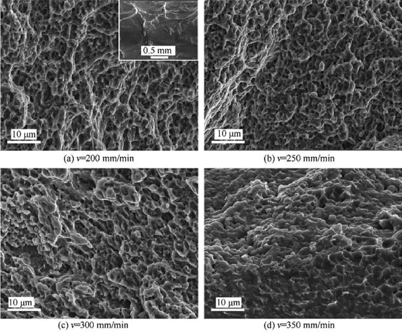
Fig. 14 SEM images presenting fracture surfaces of transverse tensile samples at different traverse speeds.
4. Conclusions
(1) The various traverse speeds affect the arc line behavior which was determined by plasticized metal flows within SZ. The BTFSW joint exhibiting a randomized pattern of arc line curve has a more random distribution of crystallographic orientations in the SZ.
(2) Dispersion and segregation of the Zr-rich particles occur in the SZ, which results in evolution of a bimodal grain structure consisted of distributed bands of 0.8-1.7 μm ultrafine grains being enrichment of Zr and adjacent coarser equiaxed grains with less Zr solute.
(3) Precipitation strengthening effect on the micro-hardness is dominate for the present joints.The micro-hardness in SZ is substantially lower than that of PM in spite of the significantly refined grains due to dissolution of the Mg-Zn based fine precipitates having strong hardening effects on alpha-Mg matrix.
(4) BTFSW joints fabricated at various traverse speeds exhibit various tensile properties. Compared with the PM,the BTFSW joints have reduced UTS and EI by 5.4%-55.1% and by 28.0%-90.6%, respectively. The BTFSW joint with weaker isotropy of texture in the SZ exhibits a superior tensile strength with adequate ductility.
Declaration of Competing Interest
The authors declare that they have no known competing financial interests or personal relationships that could have appeared to influence the work reported in this paper.
Acknowledgements
The research was sponsored by the National Science and Technology Major Project (No. 2017ZX04005001) and the Key Research and Development program of Shandong (No.2018GGX103053).
 CHINESE JOURNAL OF AERONAUTICS2021年12期
- CHINESE JOURNAL OF AERONAUTICS的其它文章
- Entropy based inverse design of aircraft mission success space in system-of-systems confrontation
- Nonlinear resonance characteristics of a dual-rotor system with a local defect on the inner ring of the inter-shaft bearing
- Failure mechanisms of bolted flanges in aero-engine casings subjected to impact loading
- Synchronized perturbation elimination and DOA estimation via signal selection mechanism and parallel deep capsule networks in multipath environment
- Improving seeking precision by utilizing ghost imaging in a semi-active quadrant detection seeker
- A high dynamics algorithm based on steepest ascent method for GNSS receiver
