Nonlinear resonance characteristics of a dual-rotor system with a local defect on the inner ring of the inter-shaft bearing
Haiming YI, Lei HOU, Peng GAO, Yushu CHEN
School of Astronautics, Harbin Institute of Technology, Harbin 150001, China
KEYWORDS Combination resonance;Dual-rotor system;Inter-shaft bearing;Local defect;Nonlinear resonance
Abstract In this paper, the nonlinear resonance characteristics of a dual-rotor system are investigated with the consideration of a local defect on the inter-shaft bearing of the system. A simplified model of the dual-rotor system is proposed by considering that there is a local defect on the inner ring of inter-shaft bearing.The local defect is modelled as an inverted isosceles trapezoidal groove,which can make great influence on the inter-shaft bearing force due to the change of radial clearance of the inter-shaft bearing. The motion equations of the dual-rotor system are formulated by using the Lagrange equation. The Runge-Kutta method is employed to solve the motion equation. The amplitude-frequency response curve of the dual-rotor system is obtained, the abnormal resonance characteristics are analyzed. In addition, the influence of defect parameters, rotors and support parameters and inter-shaft bearing parameters on the amplitude-frequency characteristics of the system are discussed.The results show that there are two main resonance peaks and four abnormal resonance peaks on the amplitude-frequency response curve of the dual-rotor with a local defect on the inner ring of the inter-shaft bearing.Through analyzing the vibration response of the abnormal resonance peaks,it is found that the first two abnormal resonances are caused by the combined resonance, which are related to the inner ring fault and the rotational speed of high or low pressure rotors, and the last two resonances are caused by the induced resonance of the inner ring fault.At the same time,when the parameters of defect,rotors and support and inter-shaft bearing change,the resonance of the system also shows the corresponding change law.
1. Introduction
In the dual-rotor system of an aero-engine, the inter-shaft bearing is prone to local defects due to the bad load-bearing environment. If it is not found and handled in time, it is easy to cause the engine vibration caused by the failure of the intershaft bearing to increase sharply, and eventually the accident
https://doi.org/10.1016/j.cja.2020.11.014 1000-9361 © 2021 Chinese Society of Aeronautics and Astronautics. Production and hosting by Elsevier Ltd.
This is an open access article under the CC BY-NC-ND license(http://creativecommons.org/licenses/by-nc-nd/4.0/).of axle holding and axle breaking occurs, which is very harmful.1Therefore,it is necessary to analyze the resonance characteristics of the dual-rotor system with partial defects of the inter-shaft bearing.
The establishment of a reasonable simplified dynamic model is the basis of relevant research. Deng et al.2simplified the inter-shaft bearing as an elastic support and simplified the supporting bearing as a support spring and a damping, then the simplified dual-rotor system model is established and the dynamic performance of the system is analyzed emphatically.Considering the nonlinear stiffness of inter-shaft bearing,Luo et al.3established a simplified nonlinear dynamic model of double rotors with reverse rotation of high and low pressure rotors, the nonlinear characteristics of the system was studied by employing the bifurcation diagram. In addition, the effects of the rotational speed,the radial clearance and the unbalances of high and low pressure rotors on the nonlinear characteristics of the system were emphatically analyzed. Liao et al.4established a dual-rotor model with simple symmetry and elastic support and damper,which can be used to analyze the influence of support stiffness, damping and inter-shaft bearing on the dual-rotor system.It is also suitable for the analysis of analytical method and clearly reveals the motion law of the dualrotor system. Chen5established a coupled dynamic model of rotor-bearing-casing with the consideration of the nonlinearity of rolling bearing and squeeze film damping,in which the finite element method was used, the nonlinear dynamic response of the system was obtained by the numerical integration method combined with the improved Newmark-β method. Lu et al.6,7established a complex discrete dynamic model of a six-point supported dual-rotor system, two simplified models are obtained by centroid method. By solving the critical speeds of the three models and comparing them with the complex discrete dynamic model, the feasibility of the simplified model is verified. Sun et al.8established a three-dimensional solid finite element model of a dual-rotor system, the Craig-Bampton modal synthesis method is used to reduce the system model and the accuracy of the reduced model in calculating critical speed and natural frequency was verified.The results are helpful to quickly solve the critical speed of the dual-rotor system.Hu et al.9established a 5-DOF for aeroengine spindle dualroter system, they found that the nonliner dynamic model of bearings and the rotational freedom of rotors have great effect on the system.
In the research of dual-rotor system with local defects of inter-shaft bearing, it is the key to simulate the local defects of the inter-shaft bearing reasonably. Gao et al.10simulated the local defect of the inter-shaft bearing as a rectangular groove with constant depth, and analyzed the amplitudefrequency response characteristics of the system when the outer ring of the inter-shaft bearing has a local defect in the simplified model of the dual-rotor system. Mcfadden and Smith11extended the single point defect model of inner ring to multi-point defect considering the geometry, vibration attenuation and load distribution of the bearing, and verified the accuracy of the model. David12studied the quasiperiodic signals caused by bearing faults, and proposed two methods of frequency variation. Patil et al.13used Hertz contact force to represent the bearing force,then established a ball bearing model for predicting local defects,the nonlinear vibration response of the fault bearing was obtained and the experimental verification was carried out. Patel et al.14established the dynamic model of single and multiple local defects on the inner or outer rings of bearings with the consideration of the quality of bearing balls, inner and outer rings, the simulation results are in good agreement with the experimental results. Liu15established a new analytical dynamic model for a Rotor-roller Bearing-Houseing Systems (RBHSs), which considers the time dependent additional contact zone excitation that caused by the local defect of the outer raceway.Tian et al.16established a four-degree-of-freedom dynamic model of outer ring fault of intermediate bearing considering timevarying displacement excitation, they studied the vibration response of the outer ring when there is a fault, and obtained the response law. Xu et al.17established a dynamic model of intermediate bearing with single defect on the rolling element,and studied the defect only on the rolling element.At the same time, the influence of different supporting forms and different rotating directions of inner and outer rings on the vibration characteristics of fault inter-shaft bearing were compared.Sun et al.18took single rotor system as the research object,and focused on the periodicity, quasi-periodicity and chaos phenomena of the system when rubbing, loosening and crack coupling failures occur. Liu and Shao19proposed a new twelve-degree-of-freedom dynamic model for rigid rotor bearing systems with a localized defect, it can give a new dynamic modeling method for vibration formulation for a rigid rotor bearing systems with and without the localized defect on the races. Ma et al.20established a lumped mass model of a rotor-bearing-seal system considering the gyroscopic effect to study the effects of the seal force and oil-film force on the first and second mode instabilities, the result contributes to a further understanding about the higher order mode instability of such a rotor system with fluid-induced forces from the oilfilm bearings and seals.Liu et al.21proposed a comparative study on the time-varying displacement model and timevarying displacement and stiffness model, studied the influences of the wave number, maximum amplitude, nonuniform distribution and vibrations of the ball bearing on the contact stiffness coefficients. Liu and Shao22established a timevarying impact force model for the localized defect with different edge shapes,and investigated the influences of the localized defect edge shapes on viberations of the unlubricated and lubricated roller bearing.
The motivation of this paper is to detect the of a dualrotor system with a local defect on the inner ring of the inter-shaft bearing. Herein a novel local defect model is proposed, which enable us to quantify the influence of the local defect on the inter-shaft bearing force due to the change of radial clearance of the inter-shaft bearing. Furthermore, the influence mechanisms of parameters on the resonance characteristics of the dual-rotor system are investigated systematically. The results of this work are helpful to refine the theory of the resonance characteristics of the dual-rotor system with inter-shaft bearing faults, which can contribute to the correlative fault diagnostics.
2. Dynamics modeling of fault dual-rotor system
2.1. Dynamics modeling of dual-rotor system
In this paper, a simplified model of a dual-rotor system from Ref. [10] is used, as shown in Fig. 1.
In the simplified model, there are four supporting points,three of them are fixed supporting bearings and the other one is an inter-shaft bearing.The supporting bearings are simplified to linear elastic force and damping force, while the inter-shaft bearing is a cylindrical roller bearing,the nonlinear Hertz contact force of which is considered.Besides,ω1,ω2represent the speed of the low and high pressure rotors; O1, O2represent the low pressure rotor’s and high pressure’s geometric centers; ki, cirepresent the stiffness and damping coefficients of linear elastic bearing respectively (i=1, 2, 3); l1, l2,l3, l4, l5, l represent the length of the corresponding position in Fig. 1.
Based on the simplified dynamic model, the kinetic energy,the potential energy,the Rayleigh’s dissipation energy and the generalized virtual work of the system can be expressed in eight degrees of freedom as follows.
Kinetic energy of the system
In the above four equations, the subscripts 1 and 2 represent the relevant parameters of low and high pressure rotors respectively; x, y represent the displacement of the centroid of the rotor in horizontal and vertical directions respectively;m, e, ω, Jp, Jdrepresent the mass of the rotor disk, the eccentricity of the rotor,the speed of the rotor,the polar moment of inertia of the rotor and the moment of inertia of the diameter of the rotor respectively;αx,βxrepresent the rotation angles of low and high pressure rotors around x-axis respectively;αy,βyrepresent the rotation angles of low and high pressure rotors around y-axis respectively; ki, cirepresent the stiffness and damping coefficients of linear elastic bearing respectively(i=1,2,3);Fx,Fyrepresent the elastic restoring force of intermediate bearings in horizontal and vertical directions respectively.
For this non-conservative system,the Lagrange equation of the second kind is used
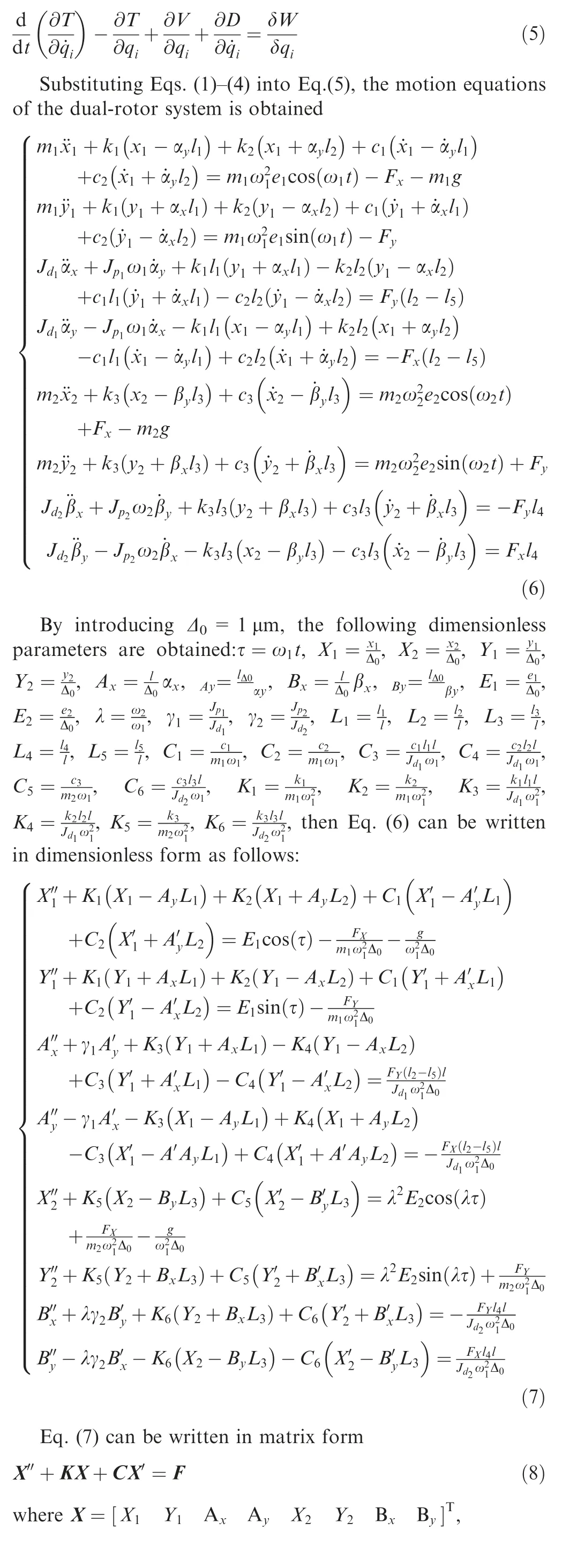
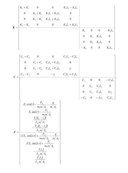
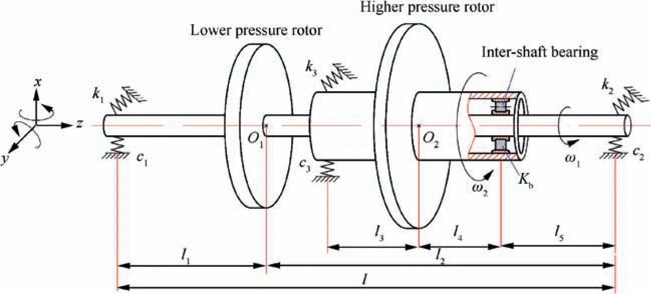
Fig. 1 Simplified model of a dual-rotor system.10
2.2. Modeling of the nonlinear contact force of the inter-shaft bearing
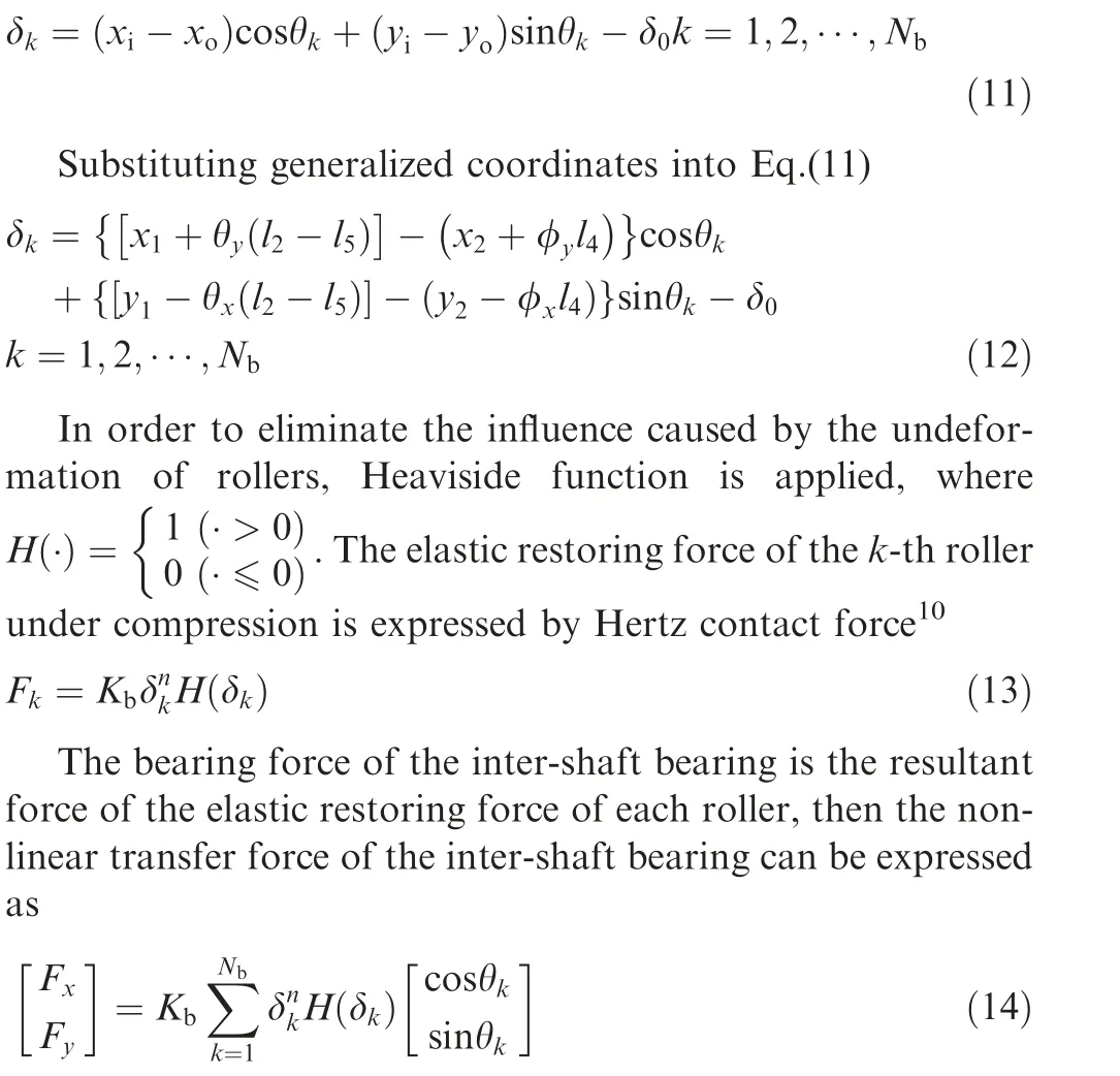
A simplified model of the inter-shaft bearing is as shown in Fig. 2. ω1and ω2are the rotational speeds of inner and outer rings of the inter-shaft bearings respectively, they have the same speed as the low and high pressure rotors; riand roare the inner and outer ring radius of inter-shaft bearing respectively; θkis the instantaneous angular position of the k-th roller of the inter-shaft bearing;Nbis the number of cylindrical rollers of the inter-shaft bearing; ωcis the speed of the cage.
Assuming that the model is ideal,that means there is no relative sliding between roller and track, and the cage speed can be expressed as

Assuming that the system is subjected to small deformation,and let xi, yi, xoand yorepresent the horizontal and vertical displacement components of inner and outer rings of the inter-shaft bearing respectively; δ0represents the radial clearance of the inter-shaft bearing, then the relative deformation of the k-th roller in contact with the inner and outer rings of the inter-shaft bearing is as follow
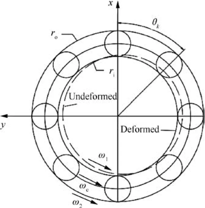
Fig. 2 Simplified model of inter-shaft bearing.

2.3. Modeling of the local defect of inter-shaft bearing
Generally,the traditional local defect is considered as a regular dent with a constant depth,10,15it assumes that the roller keeps in a constant depth when it passes the local defect.This model is convenient for theoretical calculation,but it cannot describe the process of the roller when entering,being in and leaving the local defect.In this paper,a new model is proposed.Considering there is a local defect in the inner ring of the inter-shaft bearing, in order to fully simulate the process of the roller when entering,being in and leaving the local defect,the defect is assumed to be an inverted approximate isosceles trapezoidal groove, and it is attached to the inner ring of inter-shaft bearing,as shown in Fig.3.δeis the depth of the defect at a certain constant depth;leis the total span of the defect,and assuming that the span of the part with constant depth is l0=0.8•le,and it is assumed that the excessive defect(trapezoidal waist)varies uniformly with the corresponding angle.
For a local defect whose initial angular position is φ, its instantaneous angular position θecan be written as a function of time t
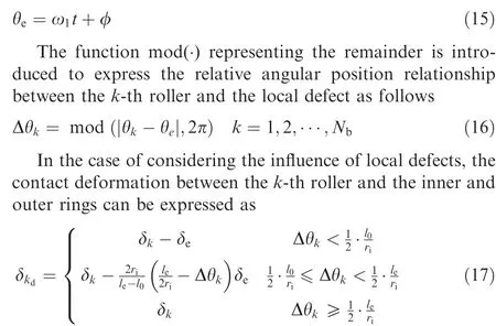
In the case of considering the local defects of the inter-shaft bearing, the elastic restoring force of the inter-shaft bearing can be expressed as

Similarly, Kbdenotes the Hertz contact stiffness of the inter-shaft bearing, the value of coefficient n is the same with Section 2.2. By substituting equation Eq. (18) into Eq. (8),the dimensionless dynamic differential equation of a dualrotor system with a local defect of the inter-shaft bearing can be obtained
2.4.Calculation of the fault characteristic frequency of the intershaft bearing
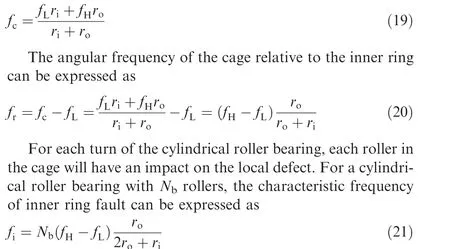
When the working surface of bearing has a local defect, there will be periodic impact between other healthy working surfaces and the local defect. The vibration caused by the impact will appear in the spectrum in the form of a special frequency component.These fault characteristic frequencies are often important ways to determine the occurrence and the type of fault in fault diagnosis. The method for calculating the characteristic frequency of bearing inner ring fault is given here [12], fHand fLare the frequencies excited by the rotational speed of high and low pressure rotors.
The angular frequency of the cage can be expressed by Eq.(9), so the speed of the cage can be expressed as
3. Nonlinear resonance characteristics of the dual-rotor system
3.1. Parameters of the model
The parameters used in this paper are as follows23

3.2. Definition of the system’s vibration amplitude
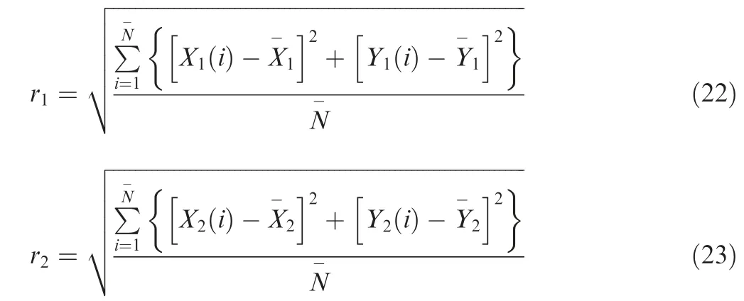
Because the vibration of the dual-rotor system is caused by the eccentric excitation of the two rotors, the vibration characteristics can not be reflected directly by the displacement response, the mean square root of energy of the vibration signal is used to reflect the vibration amplitude of the system9,the specific expressions of the amplitudes of the low and high pressure rotors are as follows:
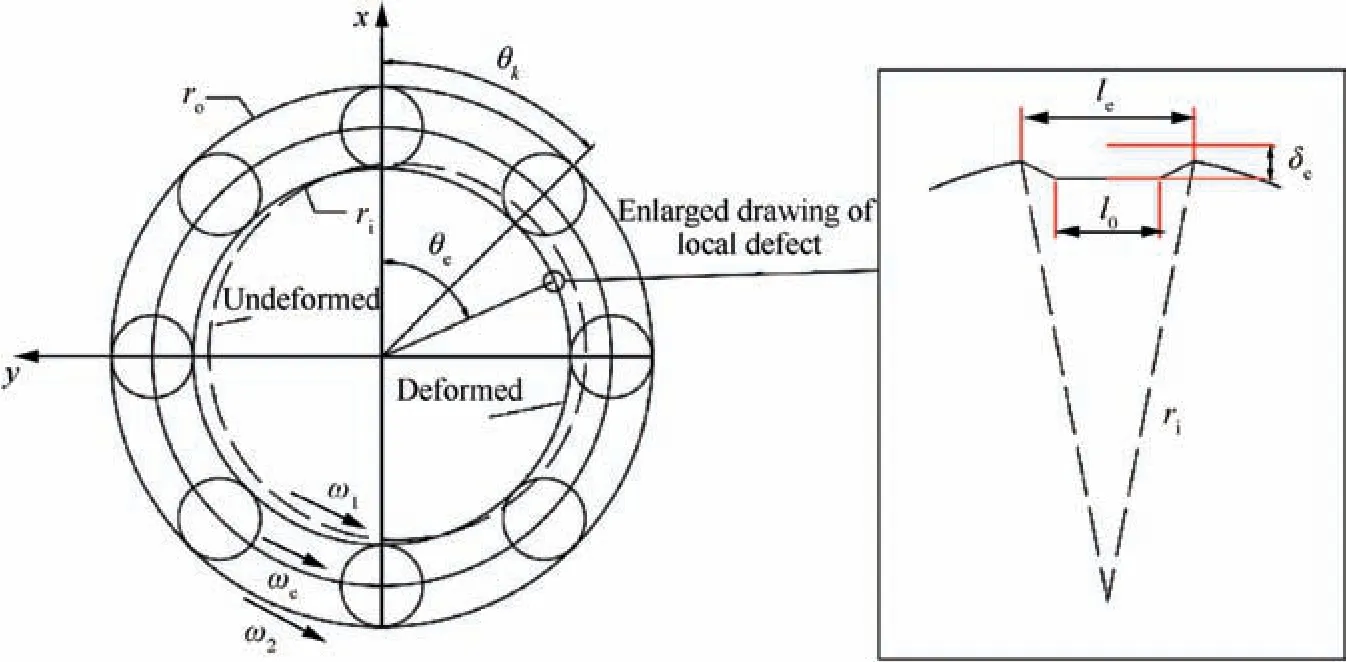
Fig. 3 Simplified model of local defect of inter-shaft bearing.

3.3. Amplitude-frequency response characteristics of the dualrotor system
The model parameters are substituted into the Eq.(8),and the equation is solved by the Runge-Kutta method of order 4,then leaving out the unstable part and taking the speed ratioλ=1.28, draw the corresponding amplitude-frequency response curve. The amplitude-frequency response curve of the healthy dual-rotor system without defects is shown in Fig. 4.
From Fig. 4. it can be seen that there are two resonance peaks appearing on the amplitude-frequency response curve of the high and low pressure rotors, and the bistable phenomenon can also be seen.The analysis of these two resonance peaks is given in Section 3.4.
Then,by using δ0=1 μm,δe=20 μm,le=10 mm,φ=0 as the parameters of the local defect, the amplitude-frequency response curve of the dual-rotor system with a local defect on the inner ring of the inter-shaft bearing(hereinafter referred to as ‘‘fault system”) is shown in Fig. 5.
Compared with the healthy dual-rotor system as shown in Fig. 4, due to the effect of the local defect, it can be found in Fig.5 that there are four abnormal resonance peaks appearing on the amplitude-frequency response curve of the high and low pressure rotors besides the two primary resonance peaks,due to the introduction of a local defect in the inner ring of the inter-shaft bearing. In addition, the bistability interval for the two primary resonances becomes larger, at the same time, the two primary resonance peaks shift slightly to the right while the maximum vibration amplitudes decrease.
3.4. Abnormal resonance analysis of fault system
From Fig. 5, it can be seen that for the fault system, the amplitude-frequency response trend of the high and low pressure rotors are the same, and the frequency positions of primary resonance peaks and abnormal resonance peaks are almost the same. Therefore, the high pressure rotor is selected for the detailed analysis below.In order to analyze the abnormal resonance peaks in detail, the peaks on the amplitudefrequency response curve of the high pressure rotor are numbered A, B, C and D from left to right, and the primary resonance peaks are numbered H and L, respectively, as shown in Fig. 6.
The rotational speeds corresponding to the resonance peak positions are ωA=582 rad/s, ωB=598 rad/s, ωC=676 rad/s, ωD=694 rad/s, ωH=650 rad/s, ωL=834 rad/s respectively. The horizontal time history, vertical time history, orbit diagram and frequency spectrum of the high pressure rotor of the fault system at each speed are shown in Figs. 7 to 12 respectively.
From Fig. 7, when ω=ωA=582 rad/s, due to the existence of the local defect, an abnormal resonance occurs in the system.The horizontal and vertical responses of the system seem like approximate periodic signals which are similar to beat vibrations. The orbit diagram of the system presents an elliptical surface with a few sharp edges and chaotic boundaries. In the spectrum diagram, there are several frequency components, including the frequencies fHand fLexcited by the rotational speed of high and low pressure rotors,their double frequencies 2fLand 2fH, and their combined frequencies 2fH-fL. Besides, the fault characteristic frequency fi, its double frequency 2fiand the combined frequencies fi-fL, 2fL-fi, 2fi-fLand 4fi-2fHthat are related to the fault characteristic frequency fiand frequencies fHand fLare also included.Among all these frequency components, 2fi-fLand 4fi-2fHare the most important and dominant ones.
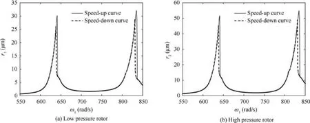
Fig. 4 Amplitude-frequency response curve of healthy system.
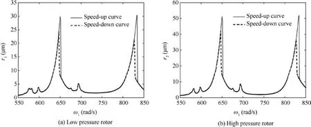
Fig. 5 Amplitude-frequency response curve of fault system.
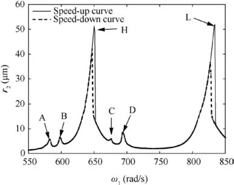
Fig. 6 Number of the resonance peaks.
From Fig. 8, when ω=ωB=598 rad/s, due to the existence of the local defect, an abnormal resonance occurs in the system.The horizontal and vertical responses of the system seem like approximate periodic signals which are similar to beat vibrations. The orbit diagram of the system presents an elliptical surface with relatively clear boundary. In the spectrum diagram,there are several frequency components,including the frequencies fHand fLexcited by the rotational speed of high and low pressure rotors,their double frequencies 2fL,and their combined frequencies 2fH-fL.Besides,the fault characteristic frequency fiand the combined frequencies fi-fL,2fL-fi,2fifL, 2fi+fL-fHand 4fi-2fHthat are related to the fault characteristic frequency fiand frequencies fHand fLare also included.Among all these frequency components, 2fi-fLis the most important and dominant one.
From Fig. 9, when ω=ωC=676 rad/s, due to the existence of the local defect, an abnormal resonance occurs in the system.The horizontal and vertical responses of the system seem like approximate periodic signals which are similar to beat vibrations, and the beat vibration phenomenon is more obvious.The orbit diagram of the system presents an elliptical surface with a few sharp edges and chaotic boundary. In the spectrum diagram, there are several frequency components,including the frequencies fHand 2fLexcited by the rotational speed of high and low pressure rotors. Besides, the fault characteristic frequency fiand the combined frequencies 2fH-fL-fi,2fi-fHand 2fi-fLthat are related to the fault characteristic frequency fiand frequencies fHand fLare also included. Among all these frequency components,except fH,fiis the most important and dominant one.
From Fig. 10, when ω=ωD=694 rad/s, due to the existence of the local defect, an abnormal resonance occurs in the system.The horizontal and vertical responses of the system seem like approximate periodic signals which are similar to beat vibrations, and the beat vibration phenomenon is more obvious.The orbit diagram of the system presents an elliptical surface with relatively clear boundary. In the spectrum diagram, there are less frequency components, including the frequencies fHand fLexcited by the rotational speed of high and low pressure rotors. Besides, the fault characteristic frequency fiand the combined frequency 3fL-fithat are related to the fault characteristic frequency fiand frequency fLare also included.Among all these frequency components fiis the most important and dominant one.

Fig. 7 Numerical simulation image of response for resonance peak A at ωA=582 rad/s.

Fig. 8 Numerical simulation image of response for resonance peak B at ωB=598 rad/s.

Fig. 9 Numerical simulation image of response for resonance peak C at ωC=676 rad/s.

Fig. 10 Numerical simulation image of response for resonance peak D at ωD=694 rad/s.

Fig. 11 Numerical simulation image of response for resonance peak H at ωH=650 rad/s.

Fig. 12 Numerical simulation image of response for resonance peak L at ωL=834 rad/s.
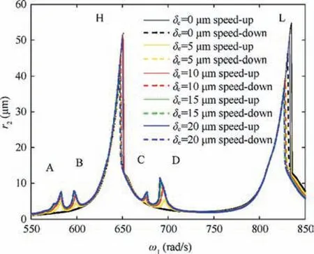
Fig. 13 Comparison of amplitude frequency characteristic curves at different defect depth.
From Fig. 11, when ω=ωH=650 rad/s, the main resonance occurs in the system. The horizontal and vertical responses of the system are harmonic signals. The orbit diagram of the system presents an ellipse. In the spectrum diagram, there are only the characteristic frequencies fHand fLexcited by the rotational speed of high and low pressure rotors.
From Fig. 12, when ω=ωL=834 rad/s, the main resonance occurs in the system. The horizontal and vertical responses of the system are harmonic signals. The orbit diagram of the system presents an ellipse. In the spectrum diagram, there are only the characteristic frequencies fHand fLexcited by the rotational speed of high and low pressure rotors.
4. Effect of parameters on fault system
4.1. Effect of defect depth
In order to investigate the effect of defect depth on the vibration characteristics of fault system, the contrast diagram of amplitude-frequency response curves and the local amplification diagrams of resonance peaks are given when defect depth δe=0 μm, δe=5 μm, δe=10 μm, δe=15 μm and δe=20-μm, as shown in Figs. 13 and 14.
From Figs. 13 and 14, with the gradual increase of defect depth, the amplitudes of the four abnormal resonance peaks increase, and the positions of abnormal resonance peaks A and B are almost unchanged, while the positions of resonance peak C shifts slightly to the right and the position of resonance peak D peak shifts to the left.The amplitudes of the two main resonance peaks decrease slightly and the positions shift slightly to the left, and the bistable intervals become larger,especially the bistable interval of the main resonance peak L.
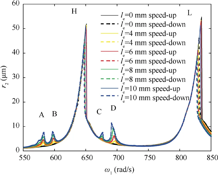
Fig. 15 Comparison of amplitude frequency characteristic curves at different defect span.
4.2. Effect of defect span
In order to investigate the effect of defect span on the vibration characteristics of fault system, the contrast diagram of amplitude-frequency response curves and the local amplification diagrams of resonance peaks are given when defect span le=0 mm, le=4 mm, le=6 mm, le=8 mm and le=10-mm, as shown in Figs. 15 and 16.
From Figs. 15 and 16, with the gradual increase of defect span, the amplitudes of the four abnormal resonance peaks increase, and the positions of abnormal resonance peaks A and B are nearly unchanged, while the position of resonance peak C shifts slightly to the right and the position of resonance peak D peak shifts to the left.The amplitudes of the two main resonance peaks decrease slightly and the positions shift slightly to the left, and the bistable intervals become larger,especially the bistable interval of the main resonance peak L.All the effects are similar to the change of defect depth.
4.3. Effect of speed ratio
In order to investigate the effect of speed ratio on the vibration characteristics of fault system, the contrast diagram of amplitude-frequency response curves and the local amplification diagrams of resonance peaks are given when speed ratio λ=1.276, λ=1.278, λ=1.280 and λ=1.282, as shown in Figs. 17 and 18.

Fig. 14 Local amplification of resonance peaks at different defect depth.

Fig. 16 Local amplification of resonance peaks at different defect span.
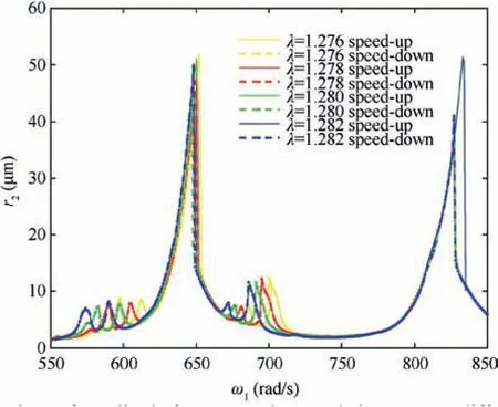
Fig. 17 Comparison of amplitude frequency characteristic curves at different speed ratio.
From Figs. 17 and 18, with the increase of the speed ratio,the amplitudes of the four abnormal resonance peaks do not change regularly,but the positions shift to the left.The amplitude of the main resonance peak H decreases slightly and the position shifts to the left, while the bistable interval becomes larger and the bistable phenomenon is more obvious. The amplitude and position of the main resonance peak L are almost unchanged.
4.4. Effect of eccentricity of the low pressure rotor
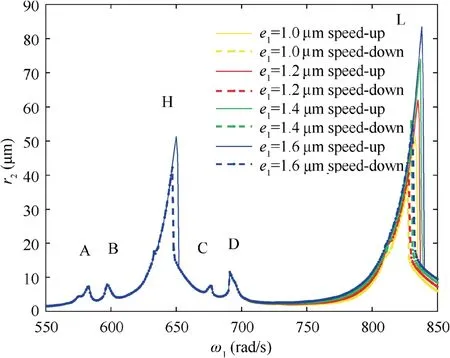
Fig. 19 Comparison of amplitude frequency characteristic curves at different eccentricity of the low pressure rotor.
In order to investigate the effect of eccentricity of the low pressure rotor on the vibration characteristics of fault system, the contrast diagram of amplitude-frequency response curves and the local amplification diagrams of resonance peaks are given when eccentricity of the low pressure rotor e1=1.0 μm,e1=1.2 μm, e1=1.4 μm and e1=1.6 μm, as shown in Figs. 19 and 20.
From Figs. 19 and 20, with the increase of the eccentricity of the low pressure rotor, the amplitudes and positions of the four abnormal resonance peaks and the main resonance peak H are nearly unchanged. Only the amplitude of the main resonance peak L increases gradually and the bistable interval becomes larger.It can be seen that the change of the eccentricity of the low pressure rotor only affects the main resonance peak which caused by the low pressure rotational speed.

Fig. 18 Local amplification of resonance peaks at different speed ratio.

Fig. 20 Local amplification of resonance peaks at different eccentricity of the low pressure rotor.
4.5. Effect of eccentricity of the high pressure rotor
In order to investigate the effect of eccentricity of the high pressure rotor on the vibration characteristics of fault system,the contrast diagram of amplitude-frequency response curves and the local amplification diagrams of resonance peaks are given when eccentricity of the high pressure rotor e2=0.3 μm, e2=0.5 μm, e2=0.7 μm and e2=0.9 μm, as shown in Figs. 21 and 22.
From Figs. 21 and 22, with the increase of the eccentricity of the high pressure rotor,the amplitudes of the four abnormal resonance peaks increase slightly and the positions are nearly unchanged.It can be found that the curves near the abnormal resonance peaks all move upwards.The amplitude of the main resonance peak H increases gradually,while the amplitude and position of the main resonance peak L basically are nearly unchanged.
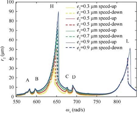
Fig. 21 Comparison of amplitude frequency characteristic curves at different eccentricity of the high pressure rotor.
4.6. Effect of stiffness of supporting bearing
In order to investigate the effect of stiffness of supporting bearing on the vibration characteristics of fault system,the contrast diagram of amplitude-frequency response curves and the local amplification diagrams of resonance peaks are given when stiffness of supporting bearing k=5.8 k0, k=6.0 k0,k=6.2 k0and k=6.4 k0, where k0=107N/m, as shown in Figs. 23 and 24.
From Figs. 23 and 24, with the increase of the stiffness of the supporting bearing, all the resonance peaks shift to the right, and the amplitudes of the two main resonance peaks and the four abnormal resonance peaks increase. In addition,the bistable intervals at the two main resonance peaks become large.
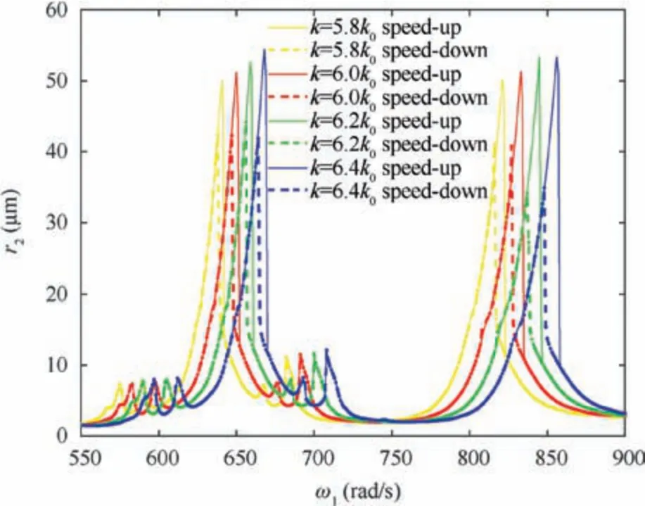
Fig. 23 Comparison of amplitude frequency characteristic curves at different stiffness of supporting bearing.

Fig. 22 Local amplification of resonance peaks at different eccentricity of the high pressure rotor.

Fig. 24 Local amplification of resonance peaks at different stiffness of supporting bearing.

Fig. 25 Comparison of amplitude frequency characteristic curves at different damping of supporting bearing.
4.7. Effect of damping of supporting bearing
In order to investigate the effect of damping of supporting bearing on the vibration characteristics of fault system, the contrast diagram of amplitude-frequency response curves and the local amplification diagrams of resonance peaks are given when damping of supporting bearing c=455 Ns/m,c=655 Ns/m, c=855 Ns/m and c=1055 Ns/m, as shown in Figs. 25 and 26.

Fig. 27 Comparison of amplitude frequency characteristic curves at different radial clearance of inter-shaft bearing.
From Figs. 25 and 26, with the increase of the damping of the supporting bearing, the amplitudes of the four abnormal resonance peaks decrease. The positions of abnormal resonance peaks A and B hardly change,while the abnormal resonance peak C shifts slightly to the left and D shifts slightly to the right.The amplitudes of the main resonance peaks H and L decrease. The positions of the main resonance peaks H and L shift to the left, and the bistable intervals become narrow.
4.8. Effect of radial clearance of inter-shaft bearing
In order to investigate the effect of radial clearance of intershaft bearing on the vibration characteristics of fault system,the contrast diagram of amplitude-frequency response curves and the local amplification diagrams of resonance peaks are given when radial clearance of inter-shaft bearing δ0=0.7 μm, δ0=0.8 μm, δ0=0.9 μm and δ0=1.0 μm, as shown in Figs. 27 and 28.

Fig. 26 Local amplification of resonance peaks at different damping of supporting bearing.
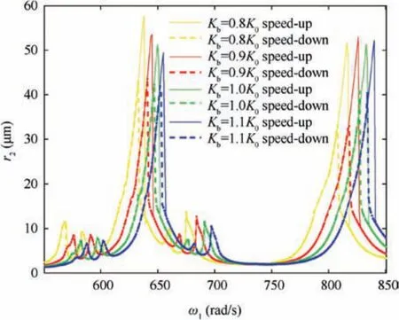
Fig. 29 Comparison of amplitude frequency characteristic curves at different stiffness of inter-shaft bearing.
From Figs. 27 and 28,with the increase of the radial clearance of inter-shaft bearing, the amplitudes of the four abnormal resonance peaks all increase and the positions all shift to the left. The amplitude the main resonance peak H increase obviously and the position shifts to the left, while the amplitude of the main resonance peak L does not change significantly and the position shifts to the left. The bistable intervals of the two main resonance peaks become larger.
4.9. Effect of stiffness of inter-shaft bearing


From Figs. 29 and 30, with the increase of the stiffness of inter-shaft bearing, all the resonance peaks shift to the right,and the amplitudes of four abnormal resonance peaks and the main resonance peak H decrease, while the amplitude of the main resonance peak L does not change regularly.In addition, the bistable intervals of the two main resonance peaks decrease.
5. Conclusions
In this paper,the dynamic model of a dual-rotor system with a local defect on the inner ring of the inter-shaft bearing has been established, the amplitude-frequency response characteristics of the system has been investigated numerically, and the influence of parameters on the nonlinear resonance characteristics of the system has been analyzed systematically.The conclusions are as follows.
(1) Two main resonance peaks and four abnormal resonance peaks will appear on the amplitude-frequency response curve of the dual-rotor system when there is a local defect on the inner ring of the inter-shaft bearing.Moreover, the bistable interval of the system will be enlarged and the two main resonance peaks will be shifted to the right by the occurrence of the local defect.
(2) Among the four abnormal resonances, the two abnormal resonances corresponding to the lower speed are the combination resonance of the characteristic frequency of inner ring fault and the rotating frequency group of high and low pressure rotor, and the two abnormal resonances corresponding to the higher speed are the fault resonance induced by the characteristic frequency of the inner ring fault.

Fig. 30 Local amplification of resonance peaks at different stiffness of inter-shaft bearing.
(3) Defect depth and span, speed ratio, eccentricity of high pressure rotor, stiffness and damping of support bearing, radial clearance and stiffness of inter-shaft bearing will affect the amplitudes or positions of the abnormal resonances. Specifically, defect depth, defect span,eccentricity of high pressure rotor, stiffness of support bearing and radial clearance of inter-shaft bearing have positive correlation with the amplitudes of the abnormal resonances, while damping of support bearing and stiffness of inter-shaft bearing have negative correlation with the amplitudes of the abnormal resonances.In addition,the increase of speed ratio or radial clearance of intershaft bearing may lead to the early appearance of the abnormal resonances, while the increase of stiffness of support bearing and stiffness of inter-shaft bearing may result in the lately appearance of the abnormal resonances.
The results will contribute to the understanding of the fault mechanisms of the inter-shaft bearing in dual-rotor systems of aero-engine, which would be helpful for the fault diagnosis of the inter-shaft bearing.The future work will focus on the nonlinear dynamic analysis of the complicated dual-roter systems with inter-shaft bearing fault and the nonlinear dynamic analysis of dual-rotor systems with both cartridge receiver and inter-shaft bearing fault.
Declaration of Competing Interest
The authors declare that they have no known competing financial interests or personal relationships that could have appeared to influence the work reported in this paper.
Acknowledgements
This work was supported by the National Natural Science Foundation of China(No.11972129)and the National Science and Technology Major Project, China (No. 2017-IV-0008-0045).
 CHINESE JOURNAL OF AERONAUTICS2021年12期
- CHINESE JOURNAL OF AERONAUTICS的其它文章
- Entropy based inverse design of aircraft mission success space in system-of-systems confrontation
- Failure mechanisms of bolted flanges in aero-engine casings subjected to impact loading
- Synchronized perturbation elimination and DOA estimation via signal selection mechanism and parallel deep capsule networks in multipath environment
- Improving seeking precision by utilizing ghost imaging in a semi-active quadrant detection seeker
- A high dynamics algorithm based on steepest ascent method for GNSS receiver
- Relevant experience learning:A deep reinforcement learning method for UAV autonomous motion planning in complex unknown environments
