Failure mechanisms of bolted flanges in aero-engine casings subjected to impact loading
Zhenzhong CAO, Fn ZHANG, Dingguo ZHANG,*, Yi YU, Ling LI,Xin GUO
a School of Science, Nanjing University of Science and Technology, Nanjing 210094, China
b AECC Shenyang Engine Research Institute, Shenyang 110015, China
KEYWORDS Ballistic tests;Bolted flanges;Failure modes;Impact resistance;Numerical analysis
Abstract In this paper, a failure evaluation criterion was proposed for the bolted casing-flange structure under impact loading. Subsequently, ballistic tests with eighteen bolted casing-flange structure specimens were conducted to validate the failure evaluation criterion. Parameter studies were then carried out using the validated FE models. Both the experimental and numerical results demonstrated the accuracy of the failure evaluation criterion. The failure evaluation criterion provided a quick and easy way to determine the failure mode of the casing connection area by using the materials and dimensions of the structure. Based on the failure evaluation criterion, designing the structural failure mode of the bolted casing-flange structure to be between flange failure and bolt failure can improve the impact resistance of the connection area of the aero-engine casings. This investigation revealed that the impact failure is not the unique criterion in evaluating the containment of the casing connection area,structural failure should also be involved in the evaluation criteria.
1. Introduction
Aero-engine casings are usually connected by bolted flange joints,which are often under extreme operating environments.Bird strikes,material defects,overheating may easily cause fan blade-out events in the aero-engine.1The releasing of highspeed blade fragments can generate extremely high energy which may lead to severe structural damages of the engine components including casing flange joints. Thus, the design of the aero-engine containment capability is significant to avoid the occurrence of penetrations which can result in severe damages of the fuselage and loss of lives.2In the past decades,numerous investigations had been conducted on the aeroengine casing containment to avoid catastrophic failure of the engine.3-13Casing flange joints also face ultimate loadings when fragments impact the casings. Therefore, the casing flange joints need to be designed to contain released blade fragments to avoid penetrations and structural failures which can cause the detachment of the connected casings.
Many researchers investigated the aerospace fasteners,14-17regarding the bolted flange joints of casings,most studies were concentrated on the field of structural dynamics.18-21Only a limited number of studies focused on the ultimate loading conditions.Czachor22presented the design of bolts and flanges to meet various operating conditions, including the blade containment problem.LS-DYNA was used to conduct the prediction of bolted joint capability under impact conditions. Bai et al.23investigated the failure of connection bolts in the study of compressor containment in the gas turbine. The study showed that adequate strength of connecting bolts is important to ensure the containment, the failure of one bolt could result in the failure of all the bolts, which can cause detachment of the whole structure. Richardson et al.24used FE method to investigate the bolt stresses in aero-engine during a fan blade-out event. These studies contributed important findings of the bolt and structure failures under impact loading conditions and highlighted the significance of the bolted joints to the blade containment capacity.However,there is a lack of investigations on the failure mechanisms and resistance evaluation of the casing flange joints under impact loading. These investigations are of great importance for the blade containment capacity of aero-engine casing connection areas.
Bolted joints are commonly used in numerous engineering fields, a large number of studies focused on the impact resistance of bolted joints,e.g.,experimental and numerical studies of bolted end plate joints under impact load,25-27tensile behavior of fasteners under high strain rate loading28and studies of the bolted composite material structures subjected to dynamic loading.29-31These studies provided insights into the failure mechanisms of various kinds of bolted joints under impact and high rate loadings. However, most of these joint configurations are quite different from the casing bolted joint structure, this makes it difficult to employ their conclusions to the present study.
The bolted L-shaped structure was used to describe the basic component of the bolted circular flange connections,32thus the theoretical analyses are simplified. Another bolted flange structure called T-stub connection can be regarded as the bolted L-shaped structure with two flanges. The T-stub connection had been widely investigated in open publications,33-36these studies investigated yield modes and failure modes of the T-stub connection.37Therefore,the failure mechanisms of the bolted L-shaped structure can be derived based on the investigations of the bolted T-stub connection. However, most of the T-stub investigations were under quasistatic tensile loading conditions, the behavior of the T-stub connection subjected to severe impact loading was less documented in the existing literature. Ribeiro et al.38,39provided a possibility to employ the T-stub failure mechanisms in high loading rate conditions.Thus,the analytical basis of the casing bolted joint could be based on the bolted L-shaped structure’failure mechanisms derived from the investigation of the Tstub connection, and the loading conditions should be analyzed systematically due to the complexity of the high-speed impact.
In this paper, a failure evaluation procedure is developed for the bolted casing-flange structure in Section 2. The structural failure evaluation criterion, which is derived based on the studies of the bolted T-stub connection by considering dynamic increase factors, is included in the evaluation procedure. It is noted that the failure criterion derived in this paper is different from the previous works in both configuration and loading conditions. In Section 3, a series of ballistic tests are conducted to validate the feasibility and accuracy of the evaluation procedure.In Section 4, numerical simulations are carried out to perform parameter studies.Based on the parameter studies, impact resistance design suggestions are proposed for the bolted casing-flange structure.
2. Theoretical analysis
2.1. Model simplification
To conduct the model simplification, two casing-flange structures joined by five bolts are cut from the aero-engine casing connection area. The casings and flanges are modeled to be plain, as shown in Fig. 1, this simplification is commonly employed in aero-engine containment studies.4,40It is worth noting that ballistic impact tests using these simplified models cannot simulate the full casing blade-out tests with the released rotating blade, and the boundary conditions of the simplified test samples in this investigation are different from the full casing structure. However, ballistic tests can give valuable information for the primary failure modes and design concepts of aero-engine casings under impact loading with less time and lower cost.4Then, a further simplification is carried out as shown in Fig.2,two casing-flange structures joined by one bolt are used to conduct the structural failure criterion analysis.These two simplified models are called bolted casing-flange structure and bolted L-shaped structure respectively in the following study.
2.2. Loading condition analysis
The failure of the bolted casing-flange structure under impact loading is hypothesized to be composed of two parts: impact failure and structural failure, Fig. 3 presents the analysis process of these two failures. The impact failure is directly generated by the impact of blades. Deformations, cracks and penetrations are likely to occur on casings and flanges in the impact failure.The impact failure mechanisms of casings have been extensively investigated in the studies of aero-engine containment. Thus, this section focuses mainly on the structural failure, and impact effects will be further discussed in the experimental study in Section 3.4.
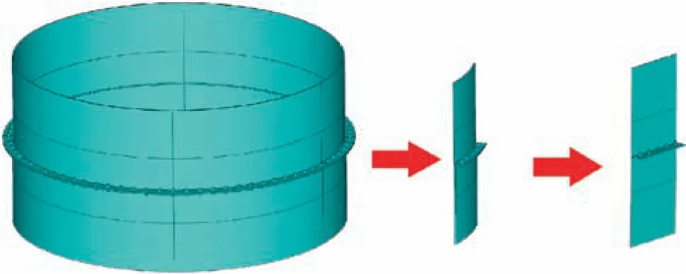
Fig. 1 Bolted casing-flange structure simplified from the aeroengine casing connection area.
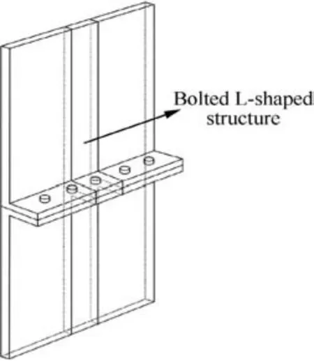
Fig. 2 Bolted L-shaped structure simplified from the bolted casing-flange structure.
Impact location has remarkable influences, however, it is uncertain which location will be struck in a fan blade-out event. Two conditions are considered: the blade impacts on both sides of the two connected casings (Fig. 4(a)), and the blade impacts on one side of the two casings(Fig.4(b)).These two impact conditions both generate deformations of the casings, which result in constraint forces at the boundaries of the casings. Consequently, the two connected casing-flange structures are separated along the Z-axis direction. The separation of the two flanges generates a tensile loading in the bolt,and a corresponding clamping force Fbis generated around the bolthole. When the blade impacts on one side of the casings, an extra shear force is generated in the bolt. That is because the two connected casing-flange structures are separated along the Y-axis direction due to the asymmetry impact.
Based on the analysis above, the two impact location conditions have a common force equilibrium along the Z-axis direction. Since the bolted L-shaped structure is symmetric, a force equilibrium analysis for one side of the structure is carried out, as shown in Fig. 4(c). A constraint force F is generated at the casing boundary due to the casing deformation.As a consequence, the deflection of the flange results in a prying force Q which is developed at the contact area between the bolt-hole and the flange outer edge,33m is the distance between the bolt-hole axis and the plastic hinge area at the flange root,n is the distance between the bolt-hole axis and the prying area,r is the fillet radius of the casing-flange connection area,e is the distance from the bolt-hole axis to the flange outer edge. The deformation of the whole structure leads to bending moments at the flange:the hogging moment M1is produced at the flange root and the sagging moment M2is produced at the bolt-hole axis. The following equations can be obtained to satisfy the equilibrium conditions:

According to the Ref. [41] n is determined by n=min(e,1.25 m) and m is determined by m=a-0.8r, where a is the distance between the bolt-hole axis and the casing outer wall.
Plastic hinges at the flange root and the bolt-hole axis are formed when M1and M2reach the flange’s plastic moment bending resistance M, which is given by33:

where tfis the flange thickness, fyfis the yield strength of the flange, beffis the effective width of the flange with one bolthole. The effective width corresponds to the smallest value of the beffin three possible yield line mechanisms33: beff=min(2πm, 4 m+1.25e, b), where b is the distance between two adjacent bolt-holes. In this condition, the plastic resistance of the flange determines the collapse mechanisms of the structure.
The bolt yields when the bolt tensile force (equals to the clamping force Fb) reaches the tensile yield load of the bolt:

where fybis the yield strength of the bolt, Abis the crosssectional area of the bolt. In this condition, the yield strength of the bolt determines the collapse mechanisms of the structure.
Due to the high velocity impact loads, the materials undergo high strain rates,which influence the plastic strengths of the materials. The strength of the materials increase for higher strain rates, thus the yield strength of the flange and bolt under impact loading can be given by involving Dynamic Increase Factors (DIFs) in static yield strengths: fyf=fyfs-•DIFfand fyb=fybs•DIFb, where fyfsand fybsare the static yield strengths of the flange and bolt respectively, DIFfand DIFbrepresent the dynamic increase factors of the materials of the flange and bolt respectively.
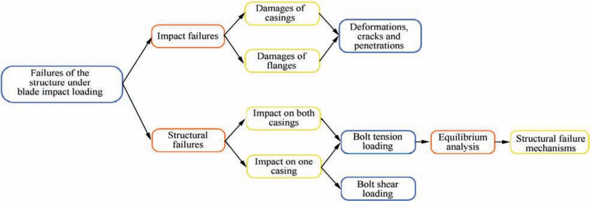
Fig. 3 Failure mechanisms analysis process of the bolted casing-flange structure under impact loading.
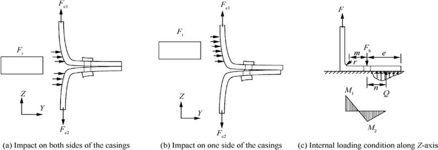
Fig. 4 Loading conditions of structure under impact loading.
2.3. Structural failure mechanisms
Material yield occurs before the ultimate failure, hence the structural failure of the bolted L-shaped structure experiences two stages:plastic yield and ultimate failure.The ultimate failure is developed on the basis of the plastic yield,thus the plastic yield modes are studied before the ultimate failure modes.
The plastic yield mode of the L-shaped bolted structure is determined by M and By. Three possible yield modes are shown in Fig. 5, the boundary conditions and details of these yield modes are as follows (also listed in Table 1):
(1) Both M1and M2reach M, hinges are formed at the flange root and the bolt-hole axis. Fbdoes not reach By, the bolt does not yield, as shown in Fig. 5 Mode 1. In this yieldmode, the flange has relatively lower resistance and the bolt has relatively higher resistance compared to the other two yield modes.
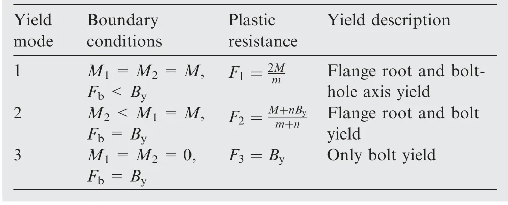
Table 1 Details of the three yield modes.
(2) M1reaches M and forms a hinge at the flange root, M2does not reach M and no hinges are formed at the bolt-hole axis.Fbreaches Byand bolt begins to yield,as shown in Fig.5 Mode 2.
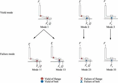
Fig. 5 Structural yield modes and failure modes of the bolted L-shaped structure.
(3)Both M1and M2do not reach M,no hinges are formed at the flange. Fbreaches Byand bolt begins to yield, as shown in Fig. 5 Mode 3. In this yield mode, the flange has relatively higher resistance and the bolt has relatively lower resistance compared to the other two yield modes.
The constraint force F,which is also regarded as the plastic resistance of the structure in T-stub structures,33can be obtained by substituting the boundary conditions into the equilibrium equations. The plastic resistances F for the three yield modes are listed in Table 1. For a specified bolted Lshaped structure, the plastic resistance takes the minimum value among the three yield modes, since the yield mode with the minimum resistance value is most favorable to reach when the structure is under impact loading,i.e.F=min(F1,F2,F3).
For the ultimate failure of the bolted L-shaped structure,four possible failure modes are developed from the three possible yield modes, as shown in Fig. 5. Mode 11 and Mode 13 are both characterized by Mode 1 mechanism, and fractures occur at the flange root and the bolt respectively. Mode 23 is developed from Mode 2 mechanism with the fracture of the bolt. Mode 33 is characterized by Mode 3 mechanism with the fracture of the bolt.
2.4. Evaluation of the structural failure modes
The occurrence of yield mode is determined by the relationship between the flange’s plastic resistance and the bolt’s plastic resistance. This relationship is denoted by βy, which can be express as the ratio between the plastic resistances corresponding to Mode 1 mechanism and that corresponding to Mode 3 mechanism37:

where βycan be calculated when the yield strengths and geometries of the flange and bolt are determined. In order to evaluate the yield mode of a specified bolted L-shaped structure, the critical values of βybetween Mode 1 and Mode 2,Mode 2 and Mode 3 are calculated respectively.
From Table 1, βy=2n/(2n+m) is obtained for F1=F2condition and βy=2 is obtained for F2=F3condition.Thus,the evaluations of the yield modes for different values of βyare obtained and listed in Table 2.
Furthermore, with reference to the ultimate failure condition, βuis given by:

where Muis the flange’s ultimate bending moment and Buis the bolt’s ultimate tensile load. Muand Bucan be calculated by replacing fyfand fybin M and Bywith the flange’s ultimate strength fufand the bolt’s ultimate tensile strength fub.The ultimate strength of the flange and bolt under impact loading can be given by involving dynamic increase factors(DIFs)in static yield strengths: fuf=fufs•DIFfand fub=fubs•DIFb, where fufsand fubsare the static ultimate strengths of the flange and bolt respectively. The limit value of βuis given by34:

Table 2 summarizes the evaluations of yield mode and failure mode for the bolted L-shaped structure. For a specified bolted L-shaped structure, material properties and geometries are determined, so that βyand βucan be calculated by Eq. (6)and Eq.(7).Thus,yield mode and failure mode of the structure can be evaluated by Table 2.To verify the feasibility and accuracy of the failure evaluation procedure,an experimental study is conducted in Section 3.
3. Experimental study
3.1. Test specimens
Blade-like projectiles made of TC4 titanium alloy with dimensions of 200 mm×90 mm×5 mm were used to simulate fan blade debris. For the test targets, six different bolted casingflange structures were used, these structures had different geometry dimensions, bolts and nuts. The dimensions of the tested casing-flange structures were adapted from real aeroengine casing structures, and they were shaped from whole 45 steel plates. Bolts and nuts were made of hightemperature alloys, which are commonly used in aero-engine fasteners. The bolts were made of GH4169 superalloy, TC4 titanium alloy and GH159 superalloy respectively.For clarity,the six different bolted casing-flange structures are represented by GH4169_1, TC4, GH159, GH4169_2, GH4169_3 and GH4169_4 respectively in this paper.
Table 3 gives details of the structures,including materials of the bolts and nuts, sizes of the bolts, tightening torques and dimensions of the casing-flange structures. D is the diameter of the bolt-hole, L is the length of the casing, b is the distance between two adjacent bolt-holes, c is the distance between the edge bolt-hole to the side edge,e is the distance from the bolthole axis to the flange outer edge,l is the distance from the casing inner edge to the flange outer edge,tfis the flange thicknessand tcis the casing thickness. The configuration of the casingflange structure is depicted in Fig. 6.

Table 2 Yield mode and failure mode determined by βy and βu.

Table 3 Details of test specimens.
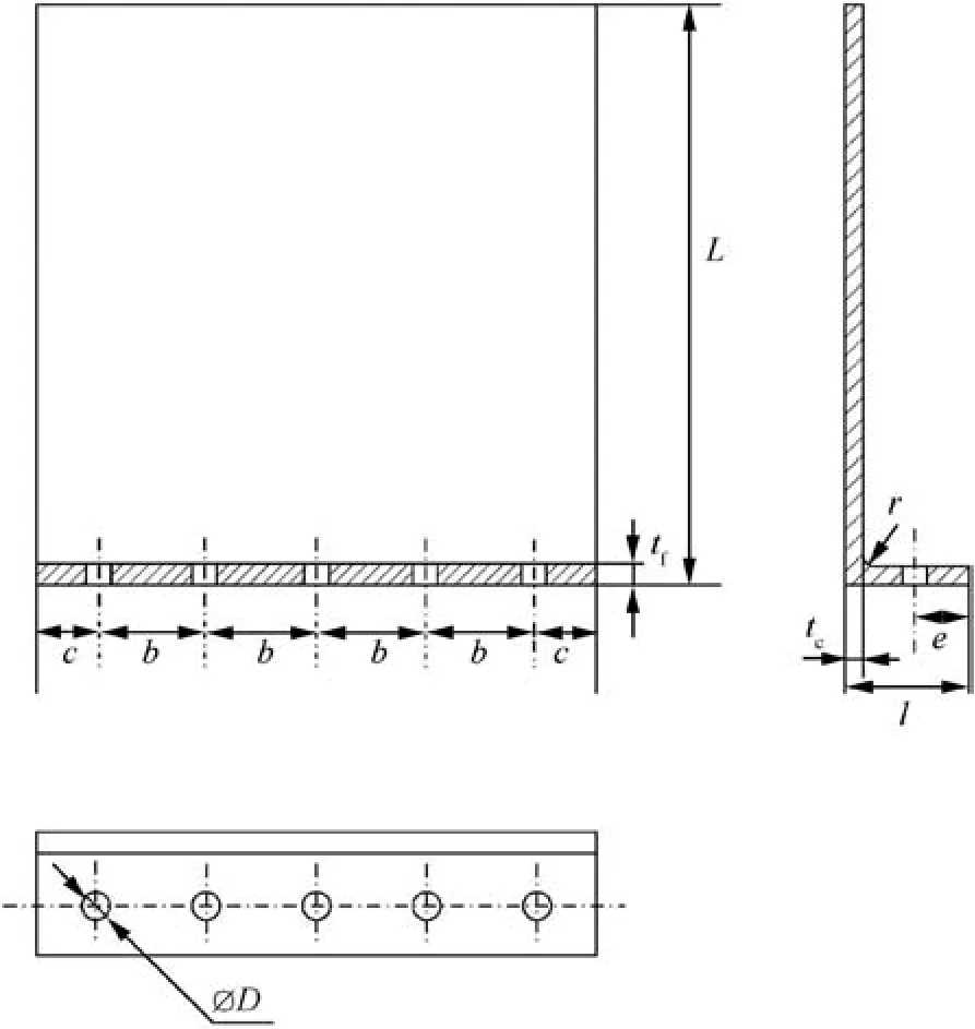
Fig. 6 Configuration and dimensions of casing flange structure.
3.2. Test setup
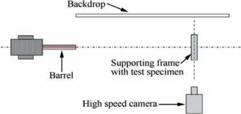
Fig. 7 Schematic diagram of the test setup.
A schematic diagram of the test setup is shown in Fig. 7. A 100 mm smoothbore powder gun was utilized to launch the projectiles to nominal impact velocities ranging from 90 to 220 m/s by adjusting the charge weight. A high-speed camera was used to record the locations, orientations and velocities of the projectiles during impacts.To ensure the projectiles were placed snugly in the gun bore and maintained normal alignment during acceleration, a set of sabots and obturators were designed to fit snugly inside the gun barrel to support the projectiles. Sabots and obturators were made of polyamide and LY-12 aluminum. Fig. 8 shows the projectile, obturators and sabots. The launch package separates prior to the impact on the target since the mass of a projectile is higher than obturators and sabots.
The target was supported by a target holder (Fig. 9) which includes a mount plate and a clamp plate. The target was inserted between the mount plate and the clamp plate, which were held together by four bolts. α is roll angle and β is pitch angle in Fig. 9. For TC4 and GH159 specimens, the thickness of the upper casing is 2 mm smaller than the lower casing. To compensate the thickness discrepancy, a 2 mm thick LY-12 aluminum bar was placed in the gap.
3.3. Structural failure prediction
In order to validate the proposed structural failure mechanisms under impact loading,yield mode and failure mode predictions using the evaluation procedure are carried out before ballistic tests.The predicting results are compared with the test results in Section 3.4.
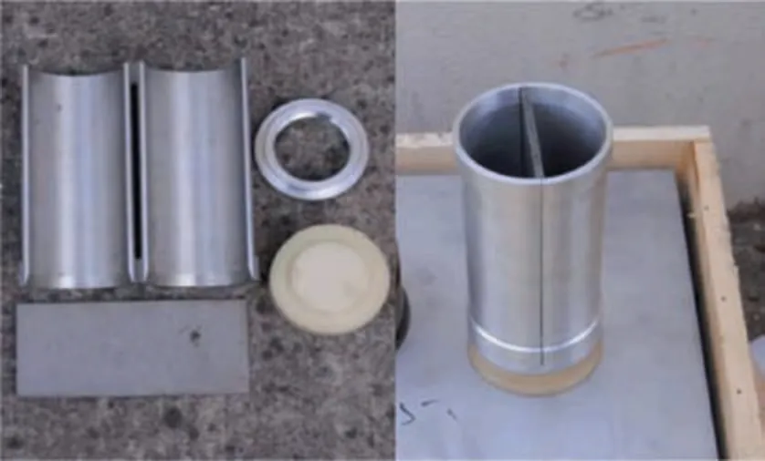
Fig. 8 Separated and packaged projectile, obturators and sabots.
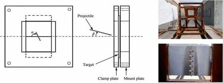
Fig. 9 Target mounting system.
Material strengths and geometry parameters of the bolts and flanges are needed for the yield mode and failure mode predictions.Since the bolts used in the tests are the real fasteners that used in the aero-engines, the yield strengths and ultimate strengths of these bolts under static loads can be adopted from China Aeronautical Materials Handbook.42,43Dynamic increase factors (DIFs) of these materials are calculated by the strain rate dependent term in Johnson-Cook constitutive model DIF=(1+C1ln˙ε*),the strain rate constant C1and the normalized plastic strain rate can be obtained from the results of split Hopkinson pressure bar tests.44,45Thus DIF=1.1 is considered for TC4 bolts, DIF=1.2 is considered for GH4169 bolts.A common used DIF of 1.139is considered for GH159 bolts since no references were found for GH159 materials. The material of the casing-flange structures is quenched and tempered 45 steel, which has higher strength than common 45 steels. Thus the strength of 45 steel can be adopted from the results of split Hopkinson pressure bar tests,46which provided the yield strength of quenched and tempered 45 steel. Thus the yield strength of 45 steel is 793.74 MPa, and the ultimate strength of 45 steel can be obtained as 980 MPa, DIF=1.4 is obtained by calculation.Table 4 lists the required parameters in the yield mode and failure mode predictions for all test specimens,the basic geometry parameters can be found in Table 3.The fillet radius r is 2 mm for all structures in this study, so that n and m can be calculated by the parameters in Table 3.
Therefore, βyand βucan be obtained by calculations with these parameters, yield modes and failure modes of the structures can be predicted by Table 4.Fig.10 depicts the βyand βudistributions of all specimens.It is clear that the yield modes of GH4169_1, TC4, GH159 and GH4169_4 specimens fall on Mode 1, while the yield modes of GH4169_2 and GH4169_3 specimens fall on Mode 2. For the failure modes,GH4169_1, GH159 and GH4169_4 specimens fall on Mode 11, TC4 specimens fall on Mode 13, while GH4169_2 and GH4169_3 specimens fall on Mode 23.
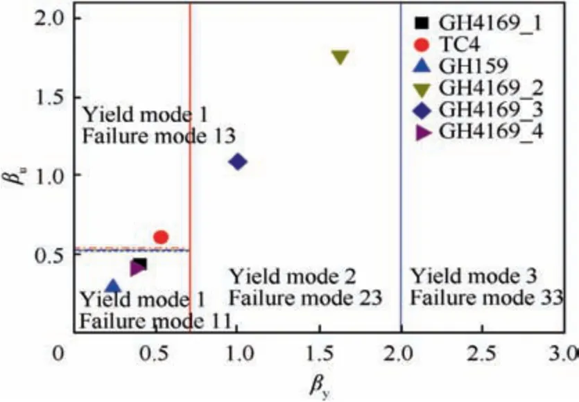
Fig. 10 βy and βu distributions of all specimens.
From the yield mode and failure mode predictions above,fracture of the flange root with complete yield of the flange may occur in GH4169_1, GH159 and GH4169_4 specimens,fracture of the bolt with complete yield of the flange may occur in TC4 specimens, while fracture of the bolt with yield of the flange root may occur in GH4169_2 and GH4169_3 specimens.
3.4. Experimental results and analyses
3.4.1. Impact conditions and results
Three tests for each specimen had been conducted.The impact velocities, impact angles and failures of the specimens areshown in Table 5.Post-test photographs of the specimens and impact locations of the projectiles are shown in Figs.11 and 12 respectively. The impact locations showed that most of the projectiles ideally struck around the center of the targets.Obturators and sabots also struck at the targets in the tests.However,the strikes of obturators and sabots have weak influences on the results since the strengths of the polyamide and aluminum are much lower than the 45 steel. Furthermore,obturators and sabots can also be regarded as parts of debris.All projectiles were undamaged after impact, while all obturators and sabots were damaged.

Table 4 Parameters and predictions for all specimens.
3.4.2. Structural failure analyses
For structural failures, predicting results are in good agreement with test results. Only yield modes occur in some tests(test 8,test 1-1,test 2-3 and test 3-3)since the impact velocities were insufficient to result in ultimate failures in these tests.An important finding was that some of yield Mode 1 tests only had slight yield along the bolt-holes at the flange, which should have totally yield under yield Mode 1 condition. This could be attributed to the high impact velocities,which result in transient impact forces on the structures. As a consequence, the transient impact caused a quick fracture at the flange root after the yield of the flange root. Thus, the whole structure failed before the bolt-holes had the opportunity to gain further yields.
The essential structural failures in the tests agreed with the predicting failure modes.Therefore, the proposed failure evaluation procedure has adequate accuracy in predicting the structural failures under impact loading.
3.4.3. Impact failure analyses
The impact effects caused penetrations, deformations and cracks in the tests. Penetrations occurred in the tests (test 1,test 9, test 3-1 and test 3-2) which have fractures at flanges,and no penetrations occurred in the bolt-fracture structural failure modes.Deformations were found in all tests,and deformations became more severe as the impact velocity increased.Cracks occurred in three forms, as shown in Fig. 13. Figs. 13(a) and (b) show cracks caused by penetrations, this kind of crack formation resulted in much more severe damages in penetrations.Figs.13(c)and(d)show cracks caused by the impact without penetration, this crack formation initiated from the impact area on the casing and could propagate to the flange and bolt-hole. In some conditions, cracks only occurred around bolt-holes (Figs. 13(e) and (f)), this should be attributed to the large deformations of the bolt-holes due to the impact near the cracked bolt-holes.
3.4.4. Influences of the impact angle and impact location
For the flange-fracture tests, the comparison of test 1 and test 9 indicates that the impact roll angle α and impact location have negligible influences on the occurrences of penetrations and structural failure modes. The specimens of these two tests are both GH4169_1, they are comparable since they had close impact velocities.The differences between these two tests were the impact roll angle and impact location. The impact roll angles of test 1 and test 9 were 82° and 10° respectively. The impact location of test 1 was on both sides of the two casings,while the impact location of test 9 was only on one side of the two casings. Despite these differences, penetration and failure Mode 11 occurred in both tests.The comparison suggests that the occurrences of penetrations and structural failure modes are not affected by the impact roll angle and impact location.For the bolt-fracture tests, test 1-1 and test 1-3 had the same test specimen and similar impact angles. The lower impact velocity in test 1-3 resulted in fractures of three bolts,while the higher impact velocity in test 1-1 did not cause any bolt fractures. This phenomenon should be attributed to the different impact locations. The blade impacted on both sidesof the two casings in test 1-1,while the impact was only on one side of the two casings in test 1-3. Discussions in Section 2.2 showed that this difference can cause extra shear forces in bolts for test 1-3. Cao et al.47presented that bolts are easier to be fractured when subjected to more shear loadings compared to more tension loadings. Thus bolts were fractured in test 1-3 despite the lower impact velocity. The comparison of these two tests indicates that bolts are easier to be fractured when the blade impacts on one side of the two casings in comparison with impact on both sides of the two casings.
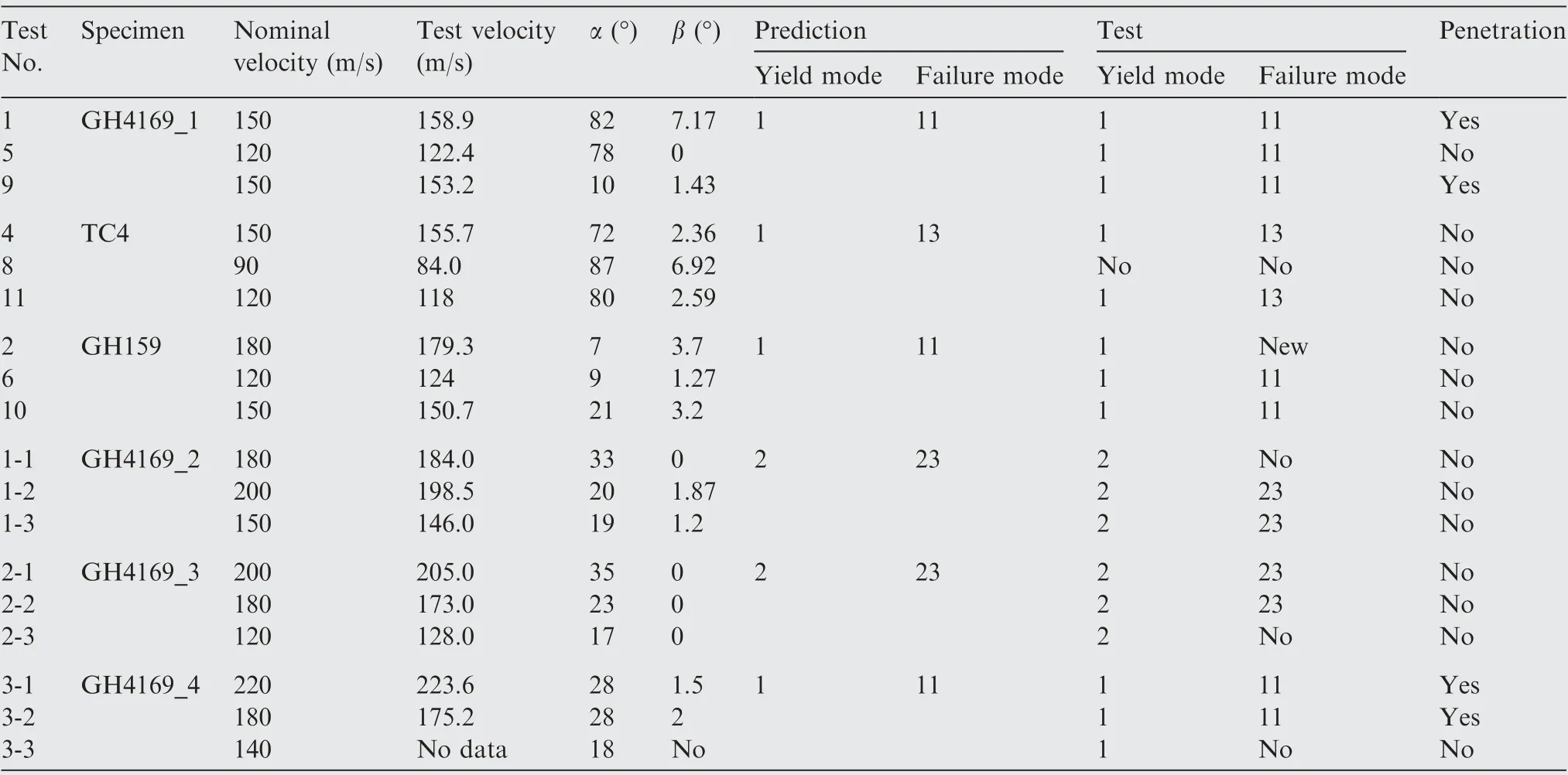
Table 5 Test conditions and results.
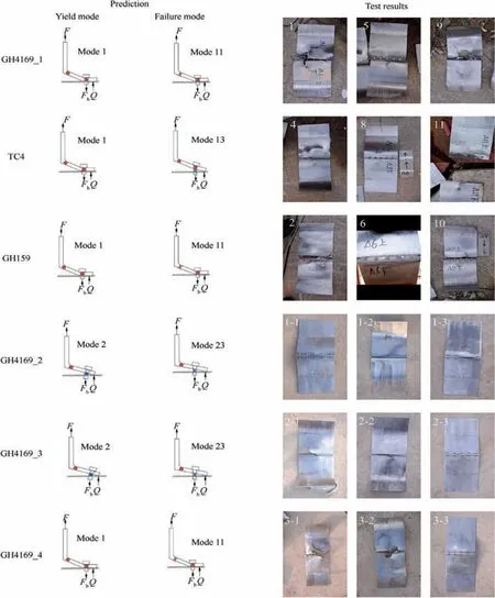
Fig. 11 Failures and damages of test specimens.
4. Numerical investigations
The failure evaluation procedure was validated by experiments in Section 3.However,the experimental studies are insufficient for further quantitative analyses, and it is extremely expensive to conduct numerous ballistic tests. Numerical simulations have been widely used to reduce expensive costs. Thus, finite element models were created to simulate the impact processes of the ballistic tests,and the FE models were validated by comparing with the experimental results. Then the validated finite element models were used to conduct the parameter studies,which further strengthen the feasibility and validity of the proposed failure mechanisms evaluation procedure under impact loading. Based on these studies, structural design suggestions were provided on the impact resistance of the bolted casingflange structure.
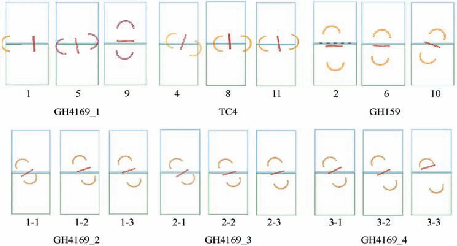
Fig. 12 Impact locations of projectiles.
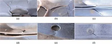
Fig. 13 Cracks in the tests.
4.1. Finite element model
4.1.1. Geometry model and meshing
LS-DYNA was used to carry out the simulations. Geometry models of specimens, projectiles, obturators, sabots and the target holder (only the mount plate and the clamp plate) were created using Solid164 hexahedral elements. The attitudes of projectiles, obturators and sabots before the striking moment were chosen to create the geometry models (Fig. 14). Bolt and nut were considered as a single part without creating threads, since existing investigations47,48showed that bolts without threads could reproduce most of the mechanical response of the bolts with threads and effectively reduce the computational time. Different mesh densities were applied to different areas of the models: the bolt-flange connection areas and the impact areas had highly refined meshes. The projectile, obturators and sabots also had refined meshes,by contrast, the areas that far from the impact location had coarser mesh in consideration of computing efficiency.Fig. 15 shows the meshed models of the entire structure,flange and bolts.
4.1.2. Contact, boundary and velocity
Contact type definitions for all contact pairs are listed in Table 6. Eroding surface to surface contact was defined in the contact pairs where penetrations may occur. The contact pairs which need to be preloaded were defined as surface to surface interference contact. The contacts between the upper and lower flanges were defined as automatic surface to surface contact. The friction coefficient was 0.15 for all contacts. The mount plate and clamp plate were constrained in all DOFs at the four corners. Velocities were defined on the projectiles,obturators and sabots.
4.1.3. Material models and properties
Strain rate dependent material models were used in the simulations in consideration of the large deformations and high strain rates during impact.Considering the computational efficiency, Simplified-Johnson-Cook model was employed for the target holder, projectiles, obturators, sabots and casing-flange structures, while Plastic-Kinematic model was used for all bolts and nuts.
Simplified-Johnson-Cook constitutive model is described by the equation49:

where σyis the flow stress, A, B, C1and N are material constants, ˙ε*is the normalized effective strain rate, and ε-p is the effective plastic strain. In this material model, the effective plastic strain at failure is defined by PSFAIL, fracture occurs when the effective plastic strain exceeds PSFAIL.
In order to obtain the parameters of Simplified-Johnson-Cook model, the most proper references were adopted to ensure the parameters represent most of the mechanical behavior of the specimens in the tests. The material of blades (TC4)is typically used for aircraft containment structures,so that the parameters of TC4 were adopted from the results of split Hopkinson pressure bar tests in the Ref.[50]note that the strengths of blades are different from the TC4 bolts. The casing-flange structures are made of quenched and tempered 45 steel which has higher strength,thus the split Hopkinson pressure bar test results for quenched and tempered 45 steel46were adopted.The parameters of LY12 aluminum were adopted from the results of tensile tests conducted by Gupta et al.51The parameters of Simplified-Johnson-Cook for these materials are listed in Table 7, E is elastic modulus, v is poisson’s ratio and ρ is density. Note that the PSFAIL value of 45 steel ranges from 0.2 to 0.3 since different manufacturing lots were used in the tests.
Plastic-Kinematic model also considers strain rate effects,and it can be described by the equation49:
The values of Plastic-Kinematic parameters for all materials are given in Table 8. Since the bolts and nuts in the tests are the real fasteners used in the aero-engines, the parameters of these materials can be adopted from China Aeronautical Materials Handbook,42,43which provided details of all these materials. In this material model, the strain rate constants C2=20 s-1and P=15 were used for GH4169 (Inconel 718),52C2=1.53×10⁵s-1and P=4.73 were used for TC4.53Since there is a lack of data of C2and P for other materials, C2and P of GH4169 were used for other superalloys(GH2132, GH159 and GH738), C2and P of TC4 were used for titanium alloy TC16. The hardening parameter βhis 0.2 for all materials.53
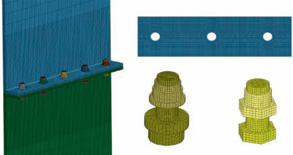
Fig. 15 Meshed models of entire structure, flange and bolts.
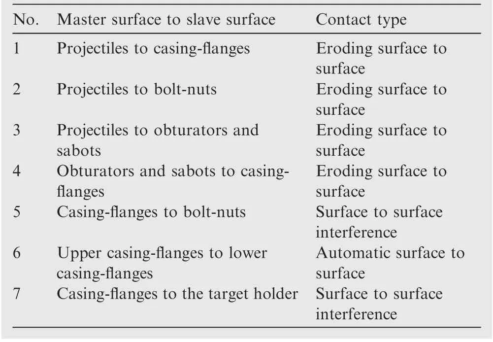
Table 6 Contact definitions.
4.1.4. Bolt preload
The tightening torques of the bolts were applied using a torque wrench in the tests.Consequently,clamping forces were generated at the flanges and tensile forces were generated in the bolts. Thus, the preloads were provided to hold the parts together. Since the tightening torque is difficult to be applied in the simulations, the tensile force generated by torque was considered to be applied in this study. The relationship between the tightening torque and the tensile force can be expressed as54:


Fig. 14 Attitudes of projectiles, obturators and sabots in modeling.

Table 7 Materials parameters for the Simplified-Johnson-Cook model.

Table 8 Materials parameters for Plastic-Kinematic model.
where T is the tightening torque,d is the diameter of the bolt,f is the tensile force in the bolt and k is a dimensionless constant.In this study, k is 0.2 according to general applications. The tensile force can be calculated once T,k and d are determined.
Applying accurate preload on bolts is significant for the numerical simulations.Inaccurate preload or applying preload with improper ways can lead to unreliable results.Modeling of preloads on bolts under static analysis had been widely studied,however,there are few investigations on preload modeling techniques for bolts under dynamic loading. Five different methods of applying preload under explicit analysis had been evaluated in the Ref. [55] these methods are adding force on the bolt and nut, adding force on the bolt shank, interference fit,thermal gradient and initial stress method.The interference fit method was chosen to apply the preload in this study in consideration of the clamping effects on the flanges. And this method can simulate the loss of the preload accurately when bolts begin to yield.
The interference fit method was carried out by modeling initial penetration between the nut and the flange, as shown in Fig. 16(a). Then, the surface to surface interference contact was defined between the nut and the flange. This contact type turns off the nodal interpenetration checks to avoid eliminating interpenetrated models at the beginning of the computation.49Then, the contact force pushes the nut model out of the flange model so that the interpenetration is removed. The interaction between the flange and the nut generated an elongation in the bolt shank and a clamping force on the flange.Figs. 16(b) and (c) present the stress distribution and plastic strain of the models.
However, little information was provided on obtaining the correct preload in the evaluated study.55In order to apply accurate preload in simulations, the study of the relationship between the bolt’s tensile force and the nut’s initial penetration was conducted. Surface to surface interference contact was defined between the nut and the flange, and load curves that scaled the contact stiffness were defined in the contact to avoid sudden forces. Different initial penetration conditions had been simulated. Fig. 17 presents that the tensile force and the initial penetration have a linear relationship.
Table 9 lists the tensile forces (calculated by Eq. (11)) and corresponding initial penetrations (interpolated from Fig. 17)
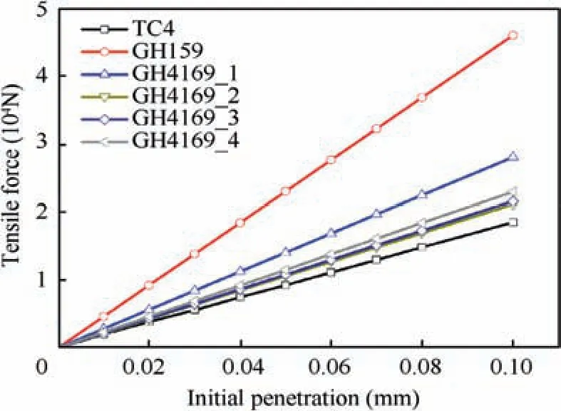
Fig. 17 Relationship between tensile force and initial penetration.

Fig. 16 Applying preload with interference fit method.
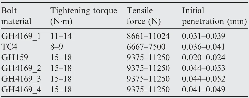
Table 9 Tensile forces and corresponding initial penetrations.

Table 10 Computing time for different mesh sizes.
in modeling.The mean values of initial penetrations were used in this study: 0.035 mm for GH4169_1, 0.039 mm for TC4,0.022 mm for GH159, 0.049 mm for GH4169_2, 0.048 mm for GH4169_3 and 0.045 mm for GH4169_4. This preload method was also employed in the contact of the casing and the target holder to clamp the target.
4.1.5. Mesh size sensitivity
Mesh size has non-negligible effects on the accuracy of the simulation results.56-59Three different mesh size models were used to conduct the mesh size sensitivity test. The mesh sizes of the casing-flange (impact area) for these models are 2 mm, 1 mm and 0.75 mm. The mesh sizes of the corresponding bolts are 1 mm,0.5 mm and 0.25 mm respectively,as shown in Table 10.The simulation results of Test 2-3 are chosen to conduct the comparison.Fig.18 shows the lateral deformations of the casings for three different mesh size models. The comparison shows that 2 mm, 1 mm and 0.75 mm casing-flange mesh size models have almost the same lateral deformations, and the simulation results are all very close to the test results. Fig. 19 shows the force-displacement curves of the bolts subjected to tension and shear loading conditions for 1 mm, 0.5 mm and 0.25 mm bolt mesh sizes. The comparison shows that the results converge near 0.25 mm bolt mesh size, and the results of 0.5 mm bolt mesh size are very close to 0.25 mm bolt mesh size.
Table 10 shows the computing time of these mesh sizes. In consideration of both accuracy and efficiency, 1 mm casingflange mesh size with 0.5 mm bolt mesh size model (Mesh 2 in Table 10) is chosen for the subsequent simulations.
4.2. FE model validation
Fig. 20 presents the failure comparisons of experimental and numerical results for some typical tests. The simulations clearly captured the main features of the experimental results,both the impact failure and the structural failure were simulated very well by the FE models. For the impact failure, casing deformations, penetrations, cracks and other impact details were captured by the FE models.For the structural failure, Mode 11 was observed in the simulations of GH4169_1,GH159 and GH4169_4 specimens. Mode 13 was observed in the simulations of TC4 specimen. Mode 23 was found in the simulations of GH4169_2 and GH4169_3 specimens. These failure modes captured in the simulations were totally in agreement with the experimental results.
For the purpose of further validation, simulation results were compared with test results regarding the lateral deformations of the casings. Since the casing-flange structures of the bolt-fracture tests were undamaged and easier to be compared,the bolt-fracture tests (TC4, GH4169_2 and GH4169_3 specimens)were chosen to compare.Fig.21 shows the lateral deformation data measurement and comparison. The comparisons of experimental and numerical lateral deformations for TC4,GH4169_2 and GH4169_3 specimens are presented in Fig.22.Good agreements were observed between experimental and numerical results. Although some discrepancies exist in local details, the overall tendencies and deformation magnitudes were simulated accurately.
The good consistency between the numerical and experimental results indicates that the FE models could capture the experimental results accurately. Therefore, validated FE models can be adopted in the following studies.
4.3. Parameter studies based on the bolt-fracture failure mode
In order to quantitatively analyze the failure modes,the bolted casing-flange structure with bolt-fracture failure mode was used since bolt-fracture is convenient to be regarded as a failure initiation. Thus, parameter studies were based on the validated FE model of TC4 specimen,which had Mode 13 failure mode under impact loading.

Fig. 18 Lateral deformations of different mesh sizes for simulations of Test 2-3.
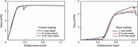
Fig. 19 Force-displacement curves of the bolts subjected to tension and shear loading conditions.
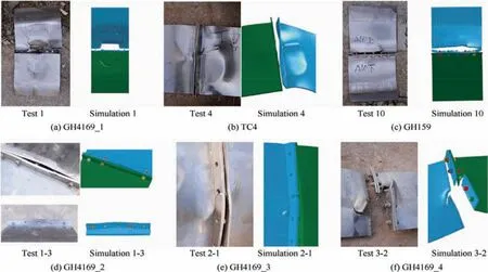
Fig. 20 The failure comparisons of experimental and numerical results.
For the purpose of simplicity,the lower casing thickness of the original model was modeled as the same thickness to the upper casing(3 mm).The target holder was replaced by proper constraints. The obturators and sabots were removed. The projectile impacted at the center of the specimens, the roll angle α was 90°and the pitch angle β was 0°.In order to evaluate the resistance of the structure, the critical velocity that represented the failure initiation was defined as the impact velocity which caused the first bolt facture. Influences of the casing-flange thickness and bolt-hole location were studied using this model.
4.3.1. Influence of the casing thickness and flange thickness
The flange thickness significantly influences the failure mechanisms of the bolted casing-flange structure. However, the effects of casing thickness were still unknown. In order to investigate the casing thickness effects and the influence of the flange thickness on the critical velocity, simulations were carried out for different casing thickness and flange thickness combinations. The casing thickness is varied from 1.5 mm to 5 mm and the flange thickness is varied from 2 mm to 3.5 mm.
Fig. 23(a) gives βyand βudistributions for different flange thickness conditions.The failure mode of the structure changes from Mode 13 to Mode 11 when flange thickness is decreased to 2 mm. In the condition of 2 mm flange thickness, flanges were fractured and bolts were pulled out from the bolt-hole,as shown in Fig. 23(b). Thus, there are no critical velocities for 2 mm flange thickness conditions according to the critical velocity definition. Though the failure mode of 2.5 mm flange thickness is almost Mode 11, bolts were still fractured in this flange thickness, which might be because the failure mode is under a mixed regime. As flange thickness increases to 3.5 mm, the failure mode of the structure changes from Mode 13 to Mode 23. Fig. 23(c) presents the failure of the 3.5 mm flange thickness condition, which had the typical failure mode of Mode 23.
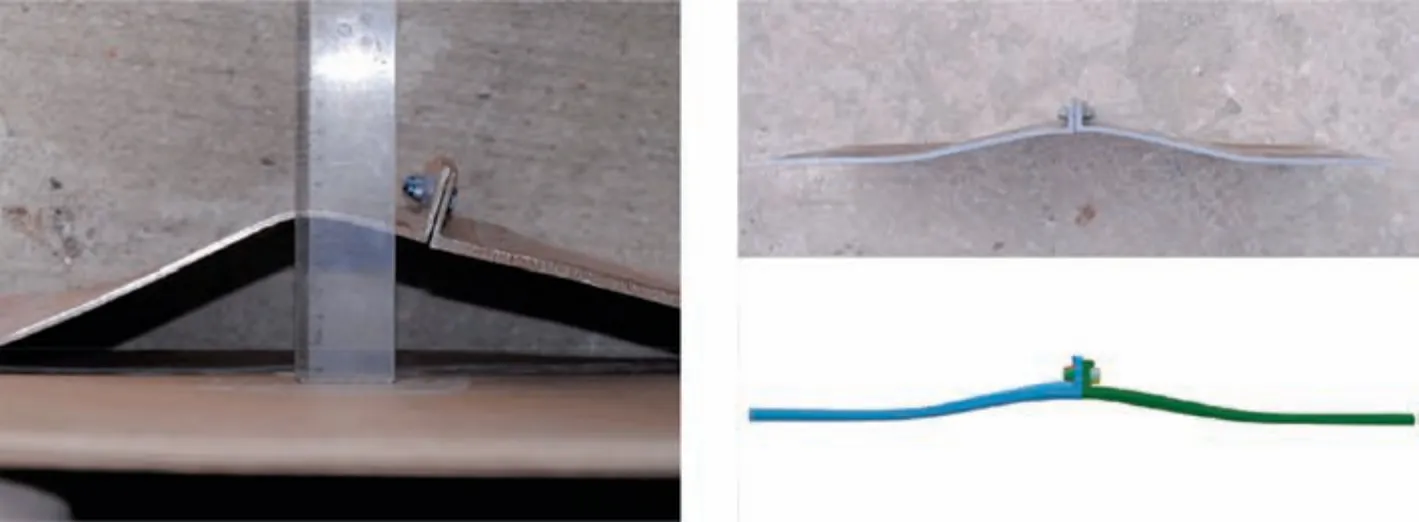
Fig. 21 Data measurement and lateral deformation comparison.
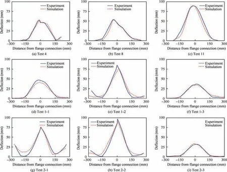
Fig. 22 Lateral deformation comparisons of the bolt-failure specimens.
For 1.5 mm casing thickness conditions,casing penetration occurred before the failure of the structure,as shown in Fig.23(d). The small casing thickness resulted in the impact failure without structural failure. This implies that the occurrence of structural failure is influenced by the casing’s thickness.
The critical velocities for different casing thickness and flange thickness combinations were simulated and shown in Fig. 24. It is observed that the critical velocity increases as the casing thickness increases for all flange thickness conditions. This observation can be explained by the change of energy absorption in casings. When the casing thickness increases, the impact energy absorbed by casings is also increased. This decreases the impact energy that transmitted to the flanges and bolts. The change of energy absorption makes the fracture of bolts more difficult, thus the critical velocity becomes higher.
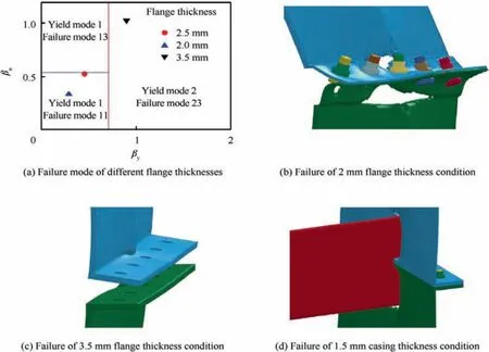
Fig. 23 Failure modes of 2 mm and 3.5 mm flange thicknesses, and 1.5 mm casing thickness conditions.
Another observation in Fig. 24 is that the increase of the flange thickness results in lower critical velocity. This should be attributed to βy, which is related to the yield modes of the structure. As tfis increased, βyincreases according to Eq.(12) which is obtained by substituting Eqs. (4) and (5) into Eq. (6). As the increase of βy, the yield mode of the structure tends to change from Mode 1 to Mode 2.As a result,the bolts are easier to be fractured, and this leads to lower critical velocity.

In order to gain insight into the effects of the geometry design on the critical velocity,the relationship between the critical velocity and tc/tfis plotted in Fig.25.It is obvious that the relationship between the critical velocity and tc/tfis approximately linear, the critical velocity increases as tc/tfincreases.This relationship would give an effective reference on the impact resistance design of the casing-flange structure thickness.
4.3.2. Influence of the bolt-hole’s location
As mentioned in Section 2,βyand βudetermine the yield mode and failure mode of the structure, and they are affected by m.Thus, the yield mode and failure mode of the structure are directly influenced by the bolt-hole’s location. Since m and e determine the bolt-hole’s location, simulations were carried out for the following three conditions to study the bolthole’s location effects:
(1) m+e=25 mm, and m equals to 8 mm, 10 mm,12 mm, 14 mm and 16 mm respectively.
(2) e=13 mm, and m equals to 8 mm, 10 mm, 12 mm,14 mm and 16 mm respectively.
(3) m=12 mm, and e equals to 11 mm, 13 mm, 15 mm,17 mm and 19 mm respectively.
As m increases to 14 mm in condition(2), the bolts are not fractured and fractures occur at the flange root.Thus,there are no critical velocities when m is larger than 14 mm in condition(2).
Fig. 26 presents the influence of bolt-hole’s location on the critical velocity. When m is determined, the only difference between condition (1) and condition (2) is e. However, they have almost the same critical velocity under the same m, as shown in Fig. 26(a). This indicates that e has negligible influences on the critical velocity. This can be verified by Fig. 26(b), which presents that the critical velocity of condition (3)is almost not influenced by e.However,the failure mode transition in condition (2) indicates that e have non-negligible effects on the occurrence of the failure mode. Fig. 26(a) also presents that the critical velocities of condition (1) and condition (2) are increased when m increases, and the relationship between the critical velocities and m is nearly linear.
For the purpose of gaining insights into the mechanisms that cause the phenomena in Fig.26,failure modes of the structures werestudiedforthethreeconditions.βu.limandβuwerecalculated and illustrated against m and e in Fig.27.Since βuis only affected by m,condition(1)and condition(2)have the same βuunder the same m.This indicates that condition(1)and condition(2)have the same ultimate strength relationship between the flange and the bolt under the same value of m.Thus,they have close critical velocity under the same value of m.
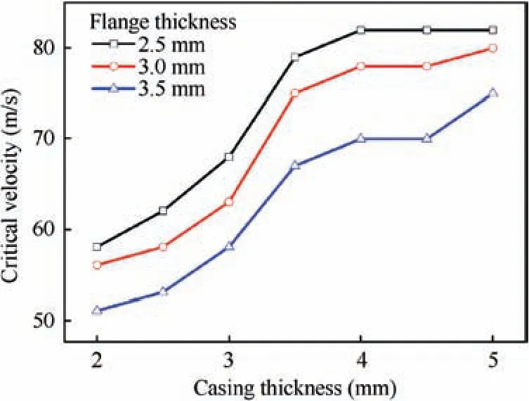
Fig. 24 Critical velocities for different casing and flange thicknesses combinations.
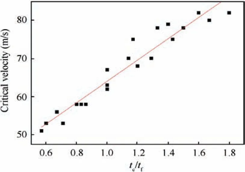
Fig. 25 Relationship between critical velocity and tc/tf.
However,βu.limin condition(1)is lower than that in condition(2)when m is larger than 12 mm.This enables the βu.limof condition(2)remarkably exceed βu,which implies that the failure mode of condition (2) is changed from Mode 13 to Mode 11.Therefore,no bolt fracture occurs in condition(2)when m is larger than 12 mm.For condition(1),bolt fracture still exist when m is larger than 12 mm,since βu.limand βuare quite close and the failure mode is between Mode 13 and Mode 11.
For condition (3), Fig. 27(c) presents that βuis kept constant when e is varied. This is because that βuis determined by m, which is a constant in condition (3). When e is larger than 13 mm, n becomes equal to 1.25 m. Thus βu.limis kept constant,as shown in Fig.27(c).Therefore,the critical velocityis almost a constant and no failure mode transitions occur when e is varied.
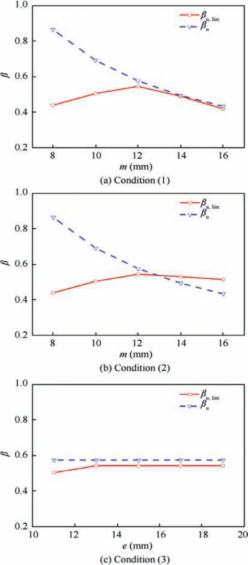
Fig. 27 Influence of bolt-hole’s location on failure mechanisms.
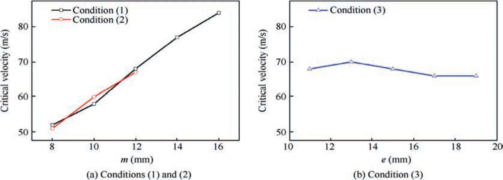
Fig. 26 Influence of bolt-hole’s location on critical velocity.
The investigation of the influence of the bolt-hole’s location reveals that the critical velocity is determined by βu. When βuincreases, the structure’s failure mode tends to transfer from Mode 13 to Mode 23.This implies that bolts tend to have relatively lower strengths compared to flanges. Thus, bolts are easier to be fractured and this results in lower critical velocities. When βudecreases, the structure’s failure mode tends to transfer from Mode 13 to Mode 11. This implies that bolts tend to have relatively higher strengths compared to flanges.Therefore, bolts are harder to be fractured and this results in higher critical velocities.
This investigation also presents that the occurrence of the failure mode is significantly influenced by e. However, this influence is ended when e is increased to be larger than 1.25 m.Furthermore, e has negligible influences on the critical velocity.
A structural design suggestion for the impact resistance can be presented based on this study. When the casing’s thickness is determined, enabling the structural failure mode to be between Mode 11 and Mode 13 is the best structural design in consideration of the structural failure resistance. For Mode 13,the structural resistance is determined by the critical velocity of bolt fracture.The critical velocity increases when the failure mode tends to transfer to be Mode 11(βudecreases).Thus,the critical velocity increases to the peak value when the failure mode is between Mode 11 and Mode 13. When the failure mode transfers to Mode 11, the structural resistance is determined by the flange’s fracture resistance,which becomes lower as βufurther decreases. Therefore, the peak structural resistance occurs in the failure mode between Mode 11 and Mode 13, as shown in Fig. 28. When the structural design of the flanges and bolts are determined, the design of the casings should obey the design of the aero-engine containment, which considers both impact resistance and reducing weight.
5. Conclusions
In this research, the failure mechanisms of the bolted casingflange structure under impact loadings have been investigated.The proposed failure evaluation procedure has been validated by ballistic tests and numerical simulations. The parameter studies provide structural design suggestions under impact loading. The main findings in the present work are as follows:
(1) Penetration of the casing-flange structure, fracture of the bolts and fracture of the flanges can occur in the failure of the bolted flange-casing structure under impact loading.Among these failures, penetration is the impact failure, fracture of the bolts and fracture of the flanges are the structural failure. The impact failure is mostly determined by casings,while the structural failure is determined by the ultimate strength relationship between the flanges and the bolts.
(2) The impact roll angle and impact location have negligible influences on the occurrence of penetrations and structural failure modes. However, the impact location affects the fracture of the bolts in bolt-fracture failure modes,bolts are easier to be fractured when impacts are on one side of the two casings in comparison with impacts are on both sides of the two casings.
(3)FE models can reproduce the ballistic tests accurately in both failure modes and lateral deformations.The validated FE model can be used to conduct further investigations to avoid the high cost of ballistic tests.
(4) The materials and dimensions of the flanges and bolts can be designed to enable the structural failure mode to be between flange failure and bolt failure to improve the impact resistance of the structure.
Declaration of Competing Interest
The authors declare that they have no known competing financial interests or personal relationships that could have appeared to influence the work reported in this paper.
Acknowledgments
The authors are grateful for the support from the National Natural Science Foundation of China (Nos. 11772158,11502113), and the Fundamental Research Funds for Central Universities, China (No. 30917011103).
 CHINESE JOURNAL OF AERONAUTICS2021年12期
- CHINESE JOURNAL OF AERONAUTICS的其它文章
- Entropy based inverse design of aircraft mission success space in system-of-systems confrontation
- Nonlinear resonance characteristics of a dual-rotor system with a local defect on the inner ring of the inter-shaft bearing
- Synchronized perturbation elimination and DOA estimation via signal selection mechanism and parallel deep capsule networks in multipath environment
- Improving seeking precision by utilizing ghost imaging in a semi-active quadrant detection seeker
- A high dynamics algorithm based on steepest ascent method for GNSS receiver
- Relevant experience learning:A deep reinforcement learning method for UAV autonomous motion planning in complex unknown environments
