A high dynamics algorithm based on steepest ascent method for GNSS receiver
Qinghu ZENG, Wenqi QIU, Jinye LIU,b,c, Rui XU, Jinheng SHI,Yongrong SUN
a Navigation Research Center, Nanjing University of Aeronautics & Astronautics, Nanjing 211106, China
b Key Laboratory of the MIIT Advanced Aircraft Navigation, Control and Health Management, Nanjing 211106, China
c Jiangsu University Collaborative Innovation Center for Satellite Communication and Navigation, Nanjing 211106, China
KEYWORDS Carrier tracking loops;Fast Fourier Transform(FFT);Global Navigation Satellite System (GNSS);High dynamics;Steepest ascent
Abstract High dynamic conditions impose critical challenges on Global Navigation Satellite System (GNSS) receivers, leading to large tracking errors or even loss of tracking. Current methods that intend to improve receivers’ adaptability for high dynamics require either complicated structures or prior statistical information of noises. This paper proposes a high dynamics algorithm based on steepest ascent method that can circumvent the deficiencies of existing methods. First,the relationship between the error of carrier tracking and the maximum of Fast Fourier Transform(FFT) outputs is established, and a performance function based on the steepest ascent method is designed. It can keep stable in high dynamics. Second, a new carrier-tracking loop is constructed by deploying the performance function. When the variation of GPS receiver acceleration ranges from 10 g to 100 g, compared with the PLL that either loses lock or keeps tracking accuracy less than 33.89 Hz,the experimental results show that the proposed method can not only keep tracking,but also achieve tracking accuracy more than 2.77 Hz.
1. Introduction
Hypersonic vehicles,1whether winged or wingless, have attracted increasing attentions from military and civil areas,thanks to their potential benefits. Hypersonic vehicles fly at high altitudes and high speeds, under severe conditions that require high level of maneuverability. GNSS is an important part of the navigation system2-6which provides high-quality navigation services for hypersonic vehicles. However, the high dynamic environments of hypersonic vehicles can easily drive GNSS receiver’s carrier-tracking loop to lose lock.7A typical solution is to widen the bandwidth and trade off the tracking performance against dynamics8: a wider bandwidth leads to better performance in high dynamics, but suffers more tracking errors as well.9
Many researchers have devoted to novel methods to improve the tracking performance of the carrier-tracking loop without sacrificing its adaptability for high dynamics. The researchers attempted in two directions: Using extra sensors for assistance, or improving the loop’s own structure.
As a necessary sensor of hypersonic vehicle, Inertial Navigation System (INS) has been used to improve the dynamic performance of carrier tracking loop in the way of GNSS/INS ultra-tight coupling.10The coupling component predicts the Doppler shifts and feed them back to the carrier-tracking loop, thus the dynamic performance of the receiver is improved.Horslund et al.used a code discriminator and a carrier discriminator as inputs of the GNSS/INS ultra-tight coupling system based on Kalman Filter (KF).11Abbott et al.defined the principle and method of GNSS/INS ultra-tight coupling12in detail in 2003,which laid a solid theoretical foundation for follow-up studies.Based on different pre-filter methods, the structures of GNSS/INS ultra-tight coupling can be divided into three categories: the basic scalar tracking loop,13-15the basic vector tracking loop16-21and the cascaded vector tracking loop.19,21,22Mark et al. reviewed the three structures23and focused on the navigation performance of the vector tracking structure24in weak signal environment.Xiyuan Chen et al.proposed a GNSS/INS ultra-tight coupling component based on Extend Kalman Filter(EKF).25Aided by external sensors, these methods have improved the tracking accuracy while retaining an acceptable dynamic performance.However, these methods require precise synchronization between the carrier-tracking loop and external sensors, which results in high costs and practical difficulties.9
Some studies have retrofitted the carrier-tracking loop’s structure to improve tracking performance in high dynamic conditions.The researchers usually focus on the discriminator,the estimator or the vector.The discriminator revision is based on the traditional Phase-Locked Loop (PLL) structure.Although assisting the PLL with the Frequency Locked Loop(FLL)26or the Wigner-Ville Distribution (WVD)27can alleviate the conflict between fitting high dynamics and obtaining high accuracies, this method still requires complicated mechanism.The estimator revision is to replace both the discriminator and the loop filter in the PLL by a single estimator,such as KF,28EKF,29Unscented Kalman Filter (UKF),8and maximum likelihood.7,30This method needs the known statistical features of noise in advance to achieve better carrier estimation. The vector-based method is to replace the individual tracking loop in each channel with a navigation filter.15With estimated position and velocity, the range and range rate of the local signal are computed and fed to generator. The primary drawback of this method is that the processed data from all satellites are closely coupled. Any error in one channel could potentially corrupt other channels.23
To circumvent the deficiencies of the two kinds of methods,this paper proposes a performance function based on the steepest ascent method that can keep a stable work state under high dynamics. Then, a new high dynamic tracking loop is constructed by deploying the proposed performance function.The rest of this paper is organized as follows: Section 2 introduces the steepest ascent method; Section 3 describes the new carrier-tracking loop; Section 4 presents simulations and experiments for the new loop and their results are analyzed.Section 5 draws some conclusions.
2. Steepest ascent method
According to the rule that multiplication in the time domain is equal to convolution in the frequency domain,S(n) is transferred from the time-domain to the frequencydomain, and the transformation is described as
where sinc(•) is the sinc function.
We take ATL/Ts= 1, TL= 1 ms as an example. The magnitude spectrum of S(n) dealt by the Discrete-Time Fourier Transform (DTFT) is depicted in Fig. 1.
As shown in Fig. 1, the spectral patterns with the frequencies Δf of -2 kHz, -1 kHz, 0 kHz, 1 kHz and 2 kHz are exactly the same, which means the spectral pattern with any frequency can be obtained by moving the magnitude spectrum of 0 kHz.

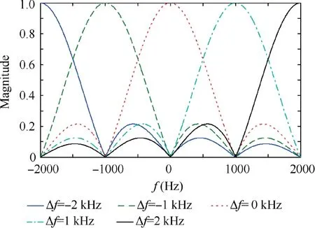
Fig. 1 Magnitude spectrum of the signal S(n).
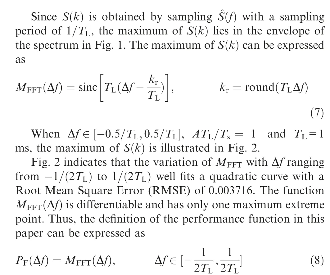
where PF(•) is the performance function. Eq. (8) is time independent, which means that the performance function is not affected by high dynamics.
The principle of the steepest ascent method31is to maximize performance function PFby adjusting Δf. According to the state update method of the steepest ascent method, the iterative process of Δf can be expressed as

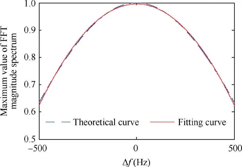
Fig. 2 Maximum value of FFT magnitude spectrum.

When the tracking error is less than 1/(2TL)Hz,the tracking loop will enter a stable tracking state. If TL=1 ms, as long as the acquisition error of Doppler shift is less than 500 Hz, the loop will enter a stable tracking state, and the change rate of Doppler shift will increase 51 Hz/s for 1 g(9.8 m/s2) acceleration of the receiver, according to the analysis of Ref. 32. The latter implies that, theoretically, if the acceleration of the receiver is not more than 500/(51×10-3) g, the loop will enter a stable tracking state.
As we intend to simplify the analyzing of the stability of the iterative process, based on the illustration in Fig. 2, we fit the performance function with a quadratic function as
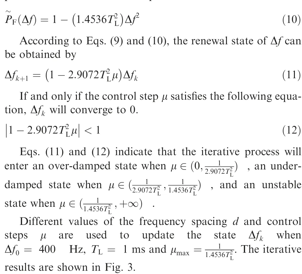
Fig.3 exhibits three important phenomena.First,when the iterative process enters an over-damped state, the setting time decreases with an increasing control step;conversely,when the iterative process enters an under-damped state,the setting time increases with an increasing control step. Second, the steadystate error is mostly related to the frequency spacing d and its value can be approximately expressed as 0.5d. Third, the setting time is almost unaffected by the frequency spacing d.
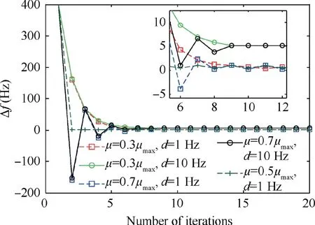
Fig. 3 Iterative process of Δfk.
3. Carrier tracking structure
Based on the steepest ascent method, a new carrier-tracking loop is designed, as illustrated in Fig. 4.
The proposed tracking loop works through five steps.First,the ranging code is stripped away by multiplying the input Intermediate Frequency(IF)signal with the local code replica.Second, the late carrier (or early) and the locally-generated punctual carrier are separately mixed with the signal that enters this step.Third,the sampling rate is reduced by an integration operation. Fourth, the FFT operation is conducted.Fifth, the carrier is controlled by a Numerically Controlled Oscillator (NCO) based on the steepest ascent method. These five steps are illustrated as follows.
Step 1. Strip the ranging code away
According to the format of the Code Division Multiple Access (CDMA) modulation signal, it is assumed that the signal structure of the discrete IF that is input into the tracking loop can be expressed as

where f2is the frequency of the local punctual carrier,and d is the frequency spacing.
If the iterative process of Δf adopts the left partial derivative equation as shown in Eq. (9), the local late carrier and the local punctual carrier will be used in this step. Similarly,if the iterative process of Δf adopts the right partial derivative equation, the local early carrier and the local punctual carrier will be used alternatively.
We take the iterative process based on the left partial derivative as an example, and the carrier mixing process can be expressed as

where Δf is the frequency difference between the received signal and the local punctual carrier, and can be represented by Δf = f2-f1.
Step 3. Down-sampling
Since the sampling rate fsis much larger than the frequency difference Δf, the down-sampling operation can be described by
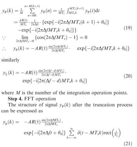
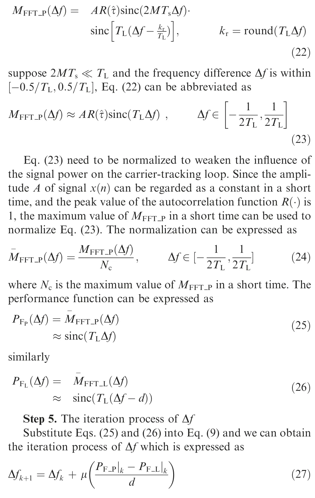
As Eq. (21) is similar to Eq. (2), after FFT processing, the relationship between the maximum value of FFT outputs and Δf can be expressed as

Fig. 4 Carrier tracking loop based on the steepest ascent method.
4. Simulations and experiments
The algorithms and design described in Sections 2 and 3 are viable under an ideal prerequisite that the tracking loop is not influenced by noises and high dynamics. To validate the practicability of our approach, we simulated an interfering environment containing noises or high dynamics for the Bei-Dou B1I signal, as well as tracked real BeiDou B1I signal in the static condition and simulated the GPS L1 signal in the dynamic condition.
4.1.Stability analysis of the carrier tracking loop in a static state
The theoretical analysis indicates that the steady state error is mostly affected by the frequency spacing d, and the setting time is mostly affected by the control step μ. Therefore, we simulated the B1I signal of BeiDou PRN 3 satellite under different noise conditions and investigated the influences of the control step μ and the frequency spacing d on the stability of the tracking loop. The simulation parameters are listed in Table 1.
The tracking loop was simulated according to the parameters in Table 1,and the results are exhibited in Figs.5,6 and 7.
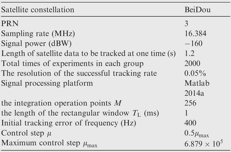
Table 1 Simulation parameters for stability analysis under a static state.
Fig. 5 depicts the influence of the frequency spacing on the steady-state error and presents two facts.First,under the same Signal Noise Ratio (SNR), the setting time is almost unchanged as the frequency spacing is increasing,which is consistent with the result of the theoretical analysis.Second,under the same frequency spacing, the setting time is shortened as SNR is rising.
Fig.6 illustrates the influence of the control step on the setting time and demonstrates that the steady-state error increases with the increase of the frequency spacing, and its value can be approximately expressed by 0.5d; and that the steady-state error is almost unaffected by the noise when the receiver is in a static state.
Fig. 7 displays the influence of the control step on the successful tracking rate. It indicates that even if SNR=-20 dB,the tracking loop holds a 100%probability of retaining the steady tracking state.
Results in Figs. 5-7 imply that a small frequency spacing can help to obtain a small steady-state error, and improving the SNR of the tracking loop can shorten the setting time without reducing the steady-state error.
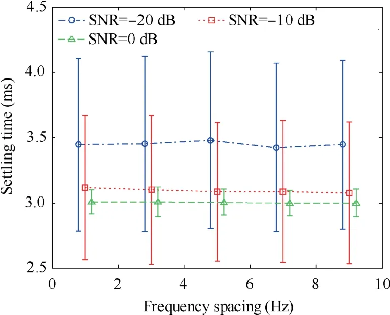
Fig.5 Influence of frequency spacing on steady-state error in the static environment.
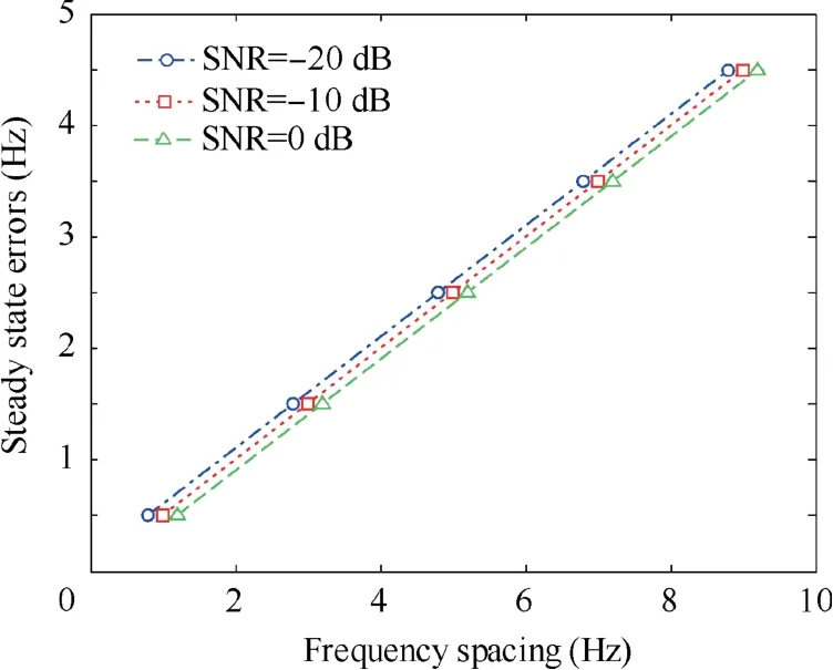
Fig. 6 Influence of control step on setting time in the static environment.

Fig. 7 Influence of control step on tacking success rate in the static environment.
4.2. Stability analysis of carrier tracking loop under high dynamics
We conducted a simulation to investigate the stability of the carrier-tracking loop when the receiver is in a dynamic state.Simulation in Section 4.1 demonstrates that when SNR=-20 dB,the setting time is the longest,so the parameters of this simulation can be set as listed in Table 2.
As Ref.32indicates that the change rate of Doppler shift increases by 51 Hz/s with 1g (9.8 m/s2)increase of the recei-ver acceleration a, we set three dynamic conditions for the investigation on the influence of the control step on the carrier tracking loop: the receiver acceleration a is set as 5g , 10g and 20g with the change rate of the Doppler shift of the received signal as 255 Hz/s, 510 Hz/s and 1020 Hz/s, respectively.The results are displayed in Figs. 8, 9.
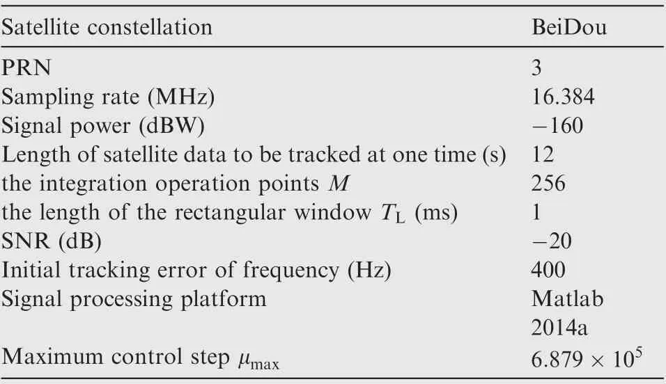
Table 2 Simulation parameters for stability analysis under high dynamics.
Figs. 8 and 9 demonstrate that even if the acceleration of the receiver is 20g , the carrier-tracking loop can enter the stable tracking state; and that increasing the control step μ can more quickly drive the tracking loop enter the stable state,although the tracking error will increase as well.
Next, in order to analyze the influence of the control step on the steady-state error, we used a series of control steps to track the same signal, and the statistical results of the steady-state error are shown in Fig. 10.
Results in Fig.10 indicate three facts.First,no matter how the control step changes, the mean steady-state error stays at 0.5 Hz,which is consistent with the conclusion under the static state.Second,the steady-state error increases with the increase of the control step,indicating that smaller control steps would be better in practice. Third, with the same control step, the steady-state error is almost unaffected when the receiver maneuverability is increasing, which validates that the proposed performance function cannot be affected by the receiver maneuverability.
Finally,we investigated the influence of the frequency spacing on the steady-state error of the carrier tracking loop in the dynamic environment, and the result is displayed in Fig. 11.
Fig. 11 reveals three phenomena. First, the mean value of the steady-state error increases with the rising frequency spacing, which is consistent with the conclusion drawn in Section 4.1. Second, the standard deviation of the steady-state error is much larger than its average value, which means that it is difficult to reduce the steady-state error by reducing the frequency spacing in the dynamic environment. Third, with the same frequency spacing, the steady-state error is almost unaffected as the receiver maneuverability improves, which again validates that the proposed performance function is not affected by the receiver maneuverability.
Results in Figs. 8-11 demonstrate that it is possible to reduce the steady-state error by reducing the control step in a dynamic environment, although this will slightly increase the setting time of the tracking loop.
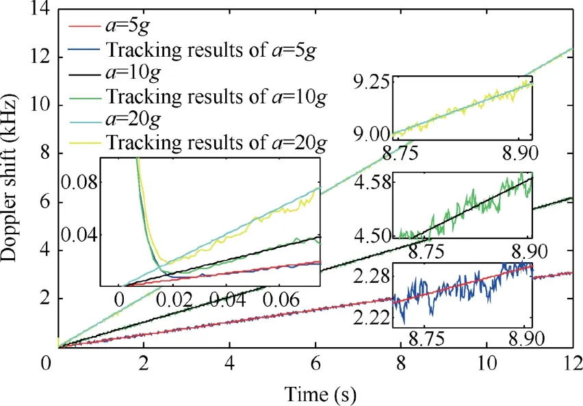
Fig.8 Tracking results of Doppler shift when the control step is 0.1μmax and the frequency spacing is 1 Hz.
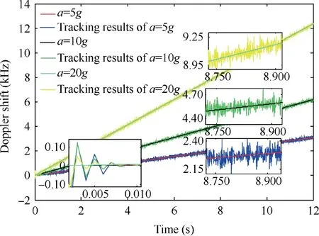
Fig.9 Tracking results of Doppler shift when the control step is 0.7μmax and the frequency spacing is 1 Hz.
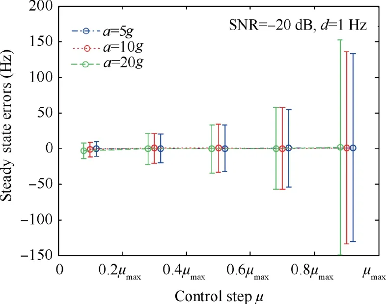
Fig.10 Influence of the control step on the steady-state error in a dynamic environment.
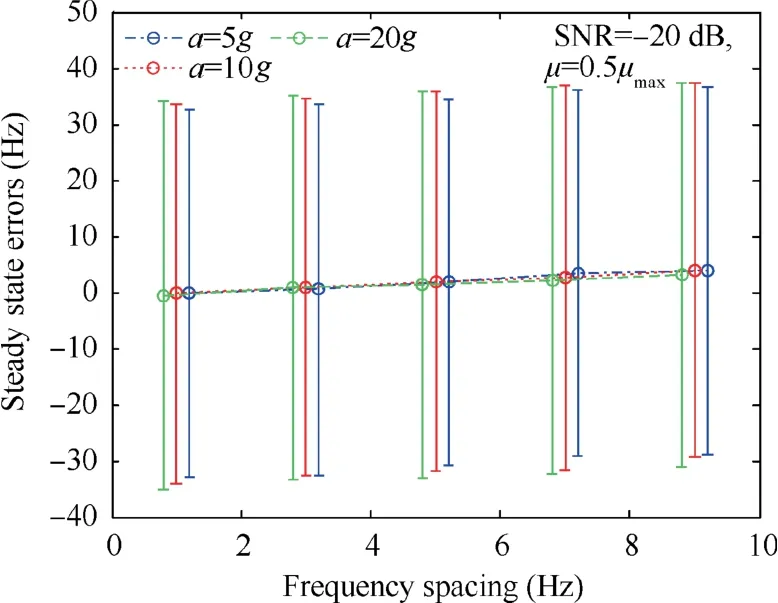
Fig. 11 Influence of the frequency spacing on the steady-state error in the dynamic environment.
4.3. Experiments on the feasibility of the proposed algorithm
We conducted two experiments on the real BeiDou B1I signal and the simulated GPS L1 signal to demonstrate the feasibility of the proposed algorithm in static and dynamic conditions,respectively.
1) Static Test
We recorded real BeiDou B1I data by using the sampler SIS600B1+L1 in a static state,and processed them on a software receiver based on MATLAB 2014a. The parameters are listed in Table 3.
Next, we deployed the proposed algorithm and the PLL to track the BeiDou PRN3 satellite signal, and the tracking results are shown in Fig. 12.
Compared with the PLL, the proposed algorithm not only achieved bit synchronization, but also improved the tracking accuracy of Doppler shift. The approximate value of the steady-state error could be expressed by 0.5d, which is consistent with the result of the theoretical analysis. The tracking errors in Figs. 12(b) and (d) are counted. The RMSE of the proposed algorithm is 0.002 Hz, and that of the PLL is 0.839 Hz,which means that the accuracy of the proposed algorithm is 99.76% higher than that of the PLL.
2) High dynamic test
We employed the GNS 8450 generator to simulate a set of Radio Frequency (RF) GPS L1 signals under a high dynamic condition. We collected the data by the IP-solutions sampler and recorded them in a PC.A simulated receiver moved along the north direction from(118.797196°E,31.943662°N)at different velocities, as shown in Fig. 13. Its acceleration reached 5 g, 10 g, 20 g and 100 g. In the simulation, signals from nine satellites are generated and logged.The distribution of the nine satellites is shown in Fig. 14.
The software receiver based on MATLAB 2014a was used to process the collected signals off-line. We also deployed the second-order PLL with a loop bandwidth of 100 Hz and a damping coefficient of 0.7, and the proposed loop with a control step of 0.5μmaxand a frequency spacing of 2 Hz to track the collected signals. The tracking results for PRN 23 are displayed in Fig.15 and the statistical tracking results of the nine satellites are listed in Table 4.
Fig. 15 shows that the proposed tracking loop is able to track signal under high dynamics with the receiver’s accelerations of 5 g,10 g,20 g and 100 g,while the PLL loses the signalwhen the acceleration reaches 10 g; and that the carrier tracking results of the proposed loop is significantly smoother than those of the PLL. It implies that the proposed algorithm has higher tracking accuracy than the PLL in the same dynamic state. In a nutshell, with an increasing receiver acceleration,the proposed algorithm can track signals stably and accurately, while the tracking ability of the PLL gradually decreases.
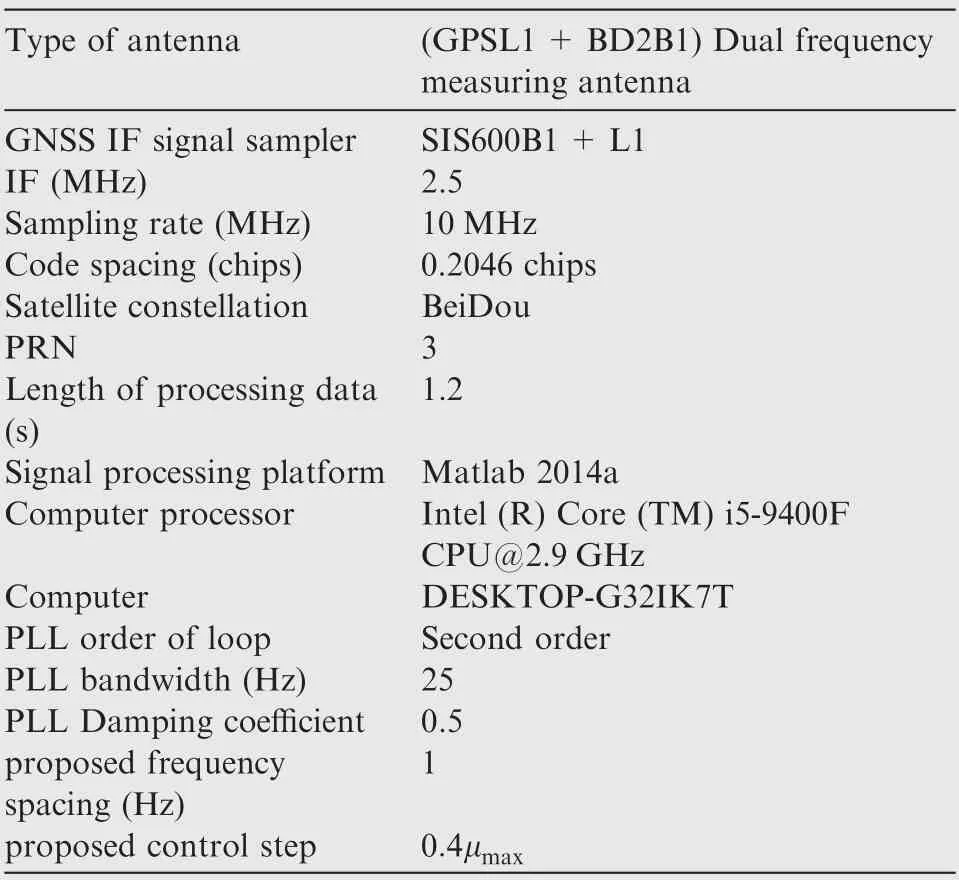
Table 3 Simulation parameters of multipath suppression.
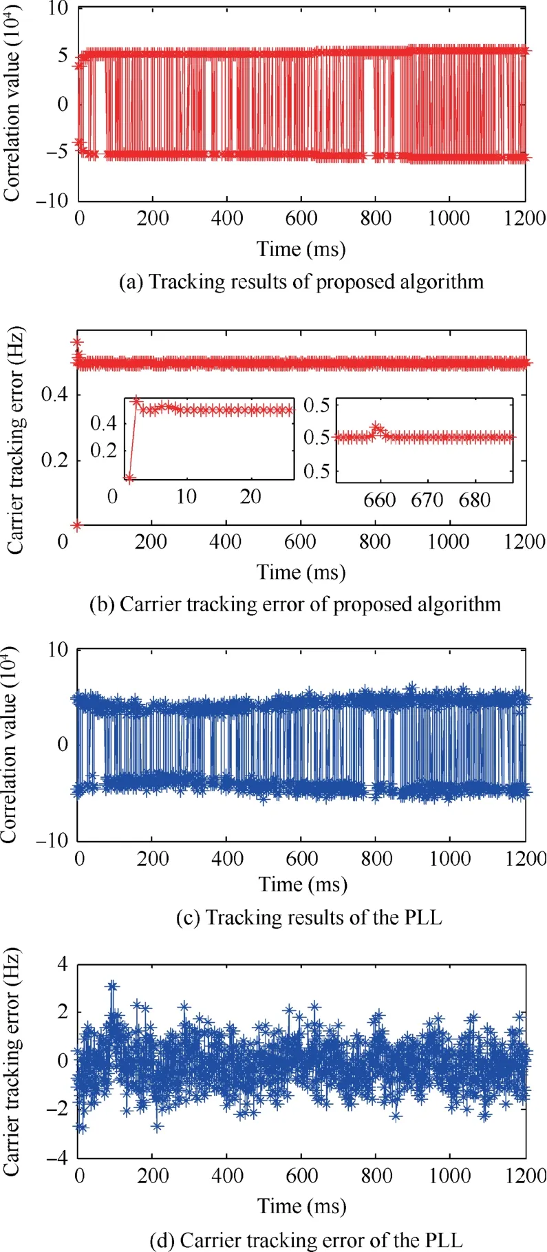
Fig. 12 Tracking results.
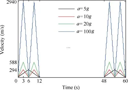
Fig. 13 Moving speeds of the receiver under different dynamic states.
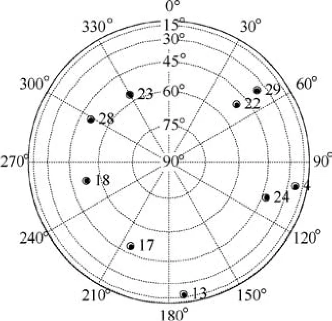
Fig. 14 GPS skyplots.
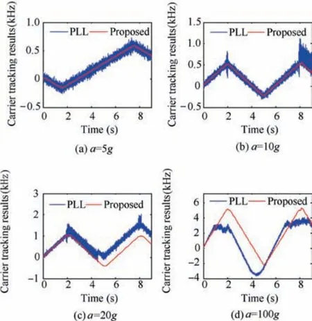
Fig. 15 Carrier tracking results of PRN 23.
Similar conclusions can be drawn from Table 4. In the statistical results, loss-of-lock for the PLL occurred when the acceleration reached 10 g. In those locking cases, the tracking error the PLL was at least 33.89 Hz; no loss-of-lock exited for the proposed loop and its tracking error was below 2.77 Hz,about 91.82% better than that of the PLL. The proposed method is more robust and can present more accurate results than the PLL.

Table 4 Statistical table of tracking error.
5. Conclusions
A new carrier-tracking loop is proposed specifically to adapt to the high dynamic environment.First,the relationship between the maximum value of the FFT magnitude spectrum and the frequency of a single frequency signal is analyzed, and a performance function that cannot be affected by the receiver’s maneuvering is designed based on the steepest ascent method.Second, a new carrier-tracking loop is constructed based on the performance function. Whether the receiver is in a static or a dynamic state,this tracking loop can track the carrier signal with high precision and without external assistance. Theoretically, when the receiver’s acceleration is lower than 500/(51×10-3) g and the acquisition error of Doppler shift is less than 500 Hz, the tracking loop can stably tracking signals if the correlation time is 1 ms. The tracking loop has a 100% probability of retaining a steady tracking state if SNR ≥-20 dB. When the receiver is in a static state, the probability that the carrier tracking error goes down less than 0.5 Hz reaches greater than 95%;while when the receiver is in a high dynamic state where the acceleration is greater than 10 g, the probability that the tracking error plumps under 35 Hz is greater than 95%. When the receiver is in a static state, the RMSE of the proposed algorithm is 0.002 Hz and that of the PLL is 0.839 Hz, which implies that the accuracy of the proposed algorithm is 99.76% higher than that of the PLL. As the acceleration of the GPS receiver ranges from 10 g to 100 g, the proposed loop can keep tracking as well as obtain a tracking accuracy more than 2.77 Hz, while the PLL either loses lock or its tracking accuracy decreases lower than 33.89 Hz.
Compared with the PLL, the proposed carrier-tracking loop is established in a parallel structure,which allows it retain a good real-time performance even its calculation amount is almost doubled.
Declaration of competing interest
The authors declare that they have no known competing financial interests or personal relationships that could have appeared to influence the work reported in this paper.
Acknowledgments
This work is funded by National Natural Science Foundation of China (Nos. 61533008, 61603181, 61673208, 61873125).
 CHINESE JOURNAL OF AERONAUTICS2021年12期
- CHINESE JOURNAL OF AERONAUTICS的其它文章
- Entropy based inverse design of aircraft mission success space in system-of-systems confrontation
- Nonlinear resonance characteristics of a dual-rotor system with a local defect on the inner ring of the inter-shaft bearing
- Failure mechanisms of bolted flanges in aero-engine casings subjected to impact loading
- Synchronized perturbation elimination and DOA estimation via signal selection mechanism and parallel deep capsule networks in multipath environment
- Improving seeking precision by utilizing ghost imaging in a semi-active quadrant detection seeker
- Relevant experience learning:A deep reinforcement learning method for UAV autonomous motion planning in complex unknown environments
