Multiaxial fatigue life prediction of composite laminates
Jingmeng WENG, Tong MENG, Weiong WEN, Shoong WENG
a Xi’an Aerospace Propulsion Institute, Xi’an 710100, China
b Academy of Space Electronic Information Technology, Xi’an 710100, China
c College of Energy and Power Engineering, Nanjing University of Aeronautics and Astronautics, Nanjing 210016, China
d School of Mechano-Electronic Engineering, Xidian University, Xi’an 710071, China
KEYWORDS Composite laminates;Fatigue damage parameter;Life prediction;Multiaxial fatigue;Multiaxial strength
Abstract A study of composite laminates under tension-torsion biaxial loading is presented. The focus is placed on fatigue lives of composite laminates under different tension-torsion biaxial fatigue loading paths. A macro-meso model used to predict multiaxial fatigue life of composite laminates is also presented in this paper. Firstly, a macro-scale 3D RVE corresponding to composite laminates is established to determine strain components in the material principal direction of each layer for each biaxial stress ratio.Secondly,a meso-scale 3D RVE corresponding to each layer with fibers distributed randomly is established, with progressive damage prediction method, biaxial strength of composite laminates can be predicted, and the final failure layer can be confirmed.Thirdly, select any one of fatigue loading path at which the final failure of composite laminates is fiber failure (matrix failure) to establish the reference curve for fiber (matrix). Finally, with reference curve, fatigue life of composite laminates under any biaxial loading path can be predicted.And numerical results show good agreements with experimental data.
1. Introduction
In addition to the excellent properties of composite materials such as fatigue resistance and corrosion resistance, composite laminates also have the advantages of designability of lay-up,simple processing technology and low material cost. Composite laminates have been widely used in aviation and aerospace industry.However,the research on static behavior and fatigue characteristics of composite laminates under complex loads is still very limited.
Cruciform specimen1is often used to test the in-plane biaxial strength of composite materials. Nevertheless, all researches2-5have demonstrated that it is almost impossible to eliminate the stress concentration in the outer fillet corner between two perpendicular arms. Therefore, the distribution of stress is not constant over the test area. The experimental results do not reflect the biaxial mechanical properties of composite materials precisely.
Tubular specimen6-8is also used to test the in-plane biaxial strength of composite materials. The experimental results showed that tubular specimen can be used to test the biaxial mechanical properties of composite materials successfully.And the forms of composite materials include filament wound composite,9,10plain-woven fabric laminate,11off-axis unidirectional fiber reinforced composites,12,13textile-reinforced composites,14et al.
Up to present,mature prediction models of biaxial strength include classical lamination theory and progressive damage model,15and mature prediction models of biaxial fatigue life include empirical method,16fatigue damage accumulation model based on the continuum damage mechanics theory,17fatigue life prediction model based on critical plane theory,12,18,19et al. However, the above fatigue life prediction methods are established at meso-scale20and only applicable for off-axis unidirectional fiber reinforced composites.Fatigue life of composite materials with complex structures are basically studied with experimental method.
Composite materials are composed of fibers and matrix,they are known as hierarchical materials with three structural levels: micro-scale, meso-scale and macro-scale. The microscale defines the distribution of fibers,the meso-scale generally relates to the fabric/lamina geometry, and the macro-scale refers to the engineering structures.20Micro-scale approaches are usually applied to predict the effective stiffness of composites21,22and predict fatigue life of unidirectional fiber reinforced composites under off-axis fatigue loading.23,24Mesoscale approaches are usually used to establish the finite element model of fabric/lamina and predict strength and fatigue life of composite materials. And macro-scale approaches are usually used to establish the finite element model of engineering structures for stress and strength analysis.
In this paper, the multiaxial mechanical behavior and fatigue life prediction model under combined tension-torsion biaxial loading are systematically studied for composite laminates. For composite laminates in the form of[45/70/0/-70/-45], multiaxial static strength tests were carried out at different biaxial stress ratios, the corresponding mechanical properties were obtained. And multiaxial fatigue tests were carried out at different biaxial stress ratios and different phase angles, the effects of biaxial stress ratio and phase angle on fatigue life have been analyzed. Based on the previously proposed method to generate random distributions of fibers in the transverse cross-section of fiber reinforced composites, a macro-meso multiaxial static strength prediction model and multiaxial fatigue life prediction model for composite laminates have been established.A good agreement can be observed between the predicted results and experimental data.
2. Mechanical property tests of composite laminates
In this section,unidirectional T700/epoxy composite laminates and tubular composite laminates are both manufactured.Unidirectional composite laminates are tested to get the mechanical properties of T700/epoxy,and tubular composite laminates are tested to get the tension-torsion biaxial mechanical properties of composite laminates.

Table 1 Mechanical properties of T700.
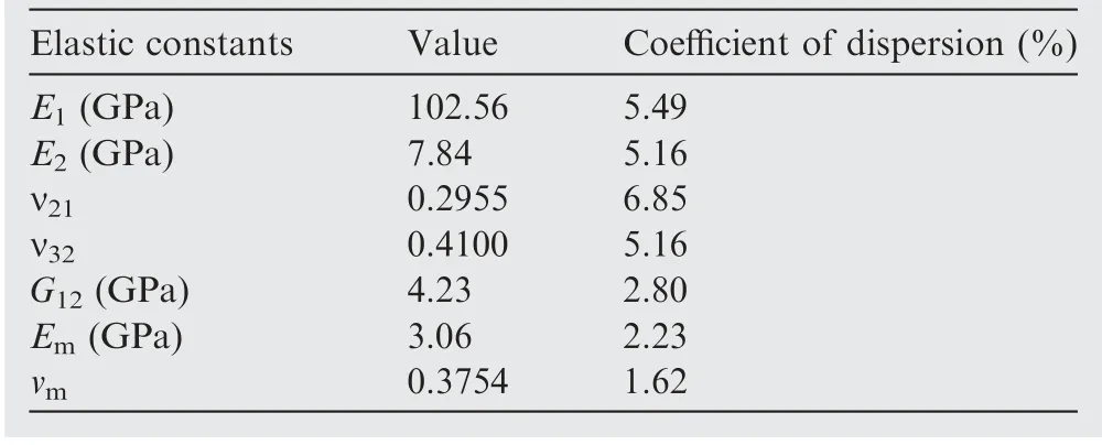
Table 2 Mechanical properties of T700/epoxy composites and epoxy.
2.1. Materials
T700 (carbon fiber) is one kind of orthotropic materials, and its mechanical properties are listed in Table 1. The biaxial mechanical test material is T700/epoxy with a volumetric fiber content of 55.53%, and its mechanical properties are tested with unidirectional composite laminates and listed in Table 2.21
2.2. Manufacture of composite laminates
In order to test the biaxial properties of composite laminates,the unidirectional prepreg of T700/epoxy is used to manufacture the tubular specimens. The detailed procedures are described below.
1) According to the stacking sequence of laminated tubular specimen, calculate the width of unidirectional prepreg corresponding to each layer.

where width is the width of unidirectional prepreg corresponding to the nth layer, Dnis the diameter of the nth layer, DIis the inner diameter of the tubular specimen, tsis the thickness of one single layer, and θnis the layer angle of the nth layer.
2) Prepare each unidirectional prepreg according to the calculated width of each layer, and the length of each unidirectional prepreg should be greater than Ln-min.

where Ln-minis the minimum theoretical length of the nth unidirectional prepreg, L is the length of the laminated tubular specimen.
3) According to Fig. 1, draw Line AB on the end of each unidirectional prepreg.
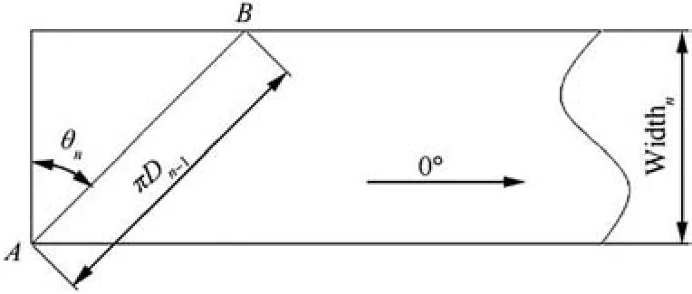
Fig. 1 Schematic diagram of unidirectional prepreg.
4) Brush silicone oil release agent on the mandrel, and wind corresponding unidirectional prepreg on the mandrel successively. During the winding process, Point A and Point B should coincide at the circumferential direction. For clarity, Fig. 2 shows the front and back views of the schematic diagram that the mandrels wind a third the width of unidirectional prepreg in 45° and 70°direction.It can be seen that when the width of each uni width directional prepreg increases to corresponding, composite laminates without seam and overlap can be processed by one winding process.
5) Line out the test section, and then enhance the gripping sections.
6) Curing the winding at elevated temperature, demouldin and cutting off the materials which are not closed in the circumferential direction, tubular laminated composite specimens can be achieved.
In this paper,the stacking sequence of composite laminates is [45/70/0/-70/-45]. The dimensions of tubular specimen are shown in Fig. 3, and the width of each unidirectional prepreg is listed in Table 3.
With this thin-walled tubular specimen (Fig. 4, where σ is axial stress and τ is torsional stress), the stress state of axial and in-plane shear stress can be obtained.
2.3. Biaxial strength testing
In the first instance, biaxial static tests were conducted to test the baseline properties of laminated tubular specimens. And the biaxial mechanical properties were tested under force control with a MTS 809 hydraulic machine at room temperature.The tests were performed with a rate of 1 N•m/sec for circumferential loading, and the loading rate for axial loading depended on the biaxial stress ratio.
Biaxial extensometer was used to measure the axial and circumferential strain.The axial stress σ and torsional stress τ are calculated by Eqs. (3) and (4). Biaxial strength tests were carried out at different biaxial stress ratios rbs(Eq. (5)). Four specimens per biaxial ratio were tested. And the results are listed in Table 4.
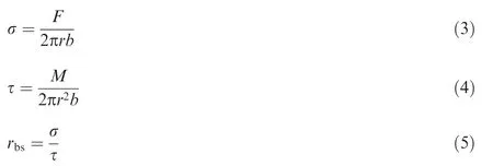
where F is axial load,M is torque,r is the average radius of test sections of the tubular specimens,and b is the thickness of test sections of the tubular specimens.
When tubular specimen is subjected to torsional loading,shear buckling may occur. A steel bar with a diameter slightly smaller than the internal diameter of the specimen was inserted into the part of gauge length of the specimen to prevent buckling. The steel insert was free and was not carrying any load during experiments.In addition,two steel bars with a diameter equals to the internal diameter of the specimen were inserted into the gripping sections of the specimen to prevent destruction of gripping sections. These steel bars were also used for all fatigue tests.
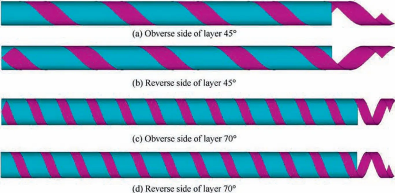
Fig. 2 Obverse and reverse sides of spindle winded with corresponding one-third width of unidirectional prepreg for layer 45° and 70°(Schematic diagram).

Fig. 3 Dimensions of tubular specimen (mm).

Table 3 Width of each unidirectional prepreg of each layer.
Experimental strengths of composite laminates under tension-torsion biaxial loading are listed in Table 4.And the fracture morphologies of composite laminates are shown in Fig.5.From Fig.5(a),it can be seen that the fracture direction is perpendicular to the direction of fibers in each layer.
2.4. Biaxial fatigue life testing
Biaxial fatigue tests were carried out at different biaxial stress ratios and different phase angles. 5 different loading paths(Fig.6)were chosen to analyze the effects of biaxial stress ratio and phase angle on fatigue life.The frequency was kept at 2 Hz for all tests to ensure no appreciable temperature increase wasdetected during cycling at all loading conditions. Typically,three specimens were tested for each loading path and stress level. The failure of the specimen is defined as complete separation occurred.

Table 4 Experimental results of composite laminates under external biaxial loading.
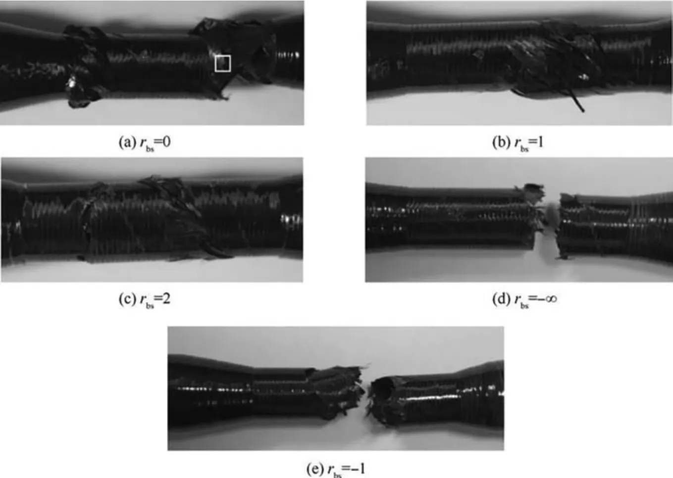
Fig. 5 Fracture morphologies of composite laminates.
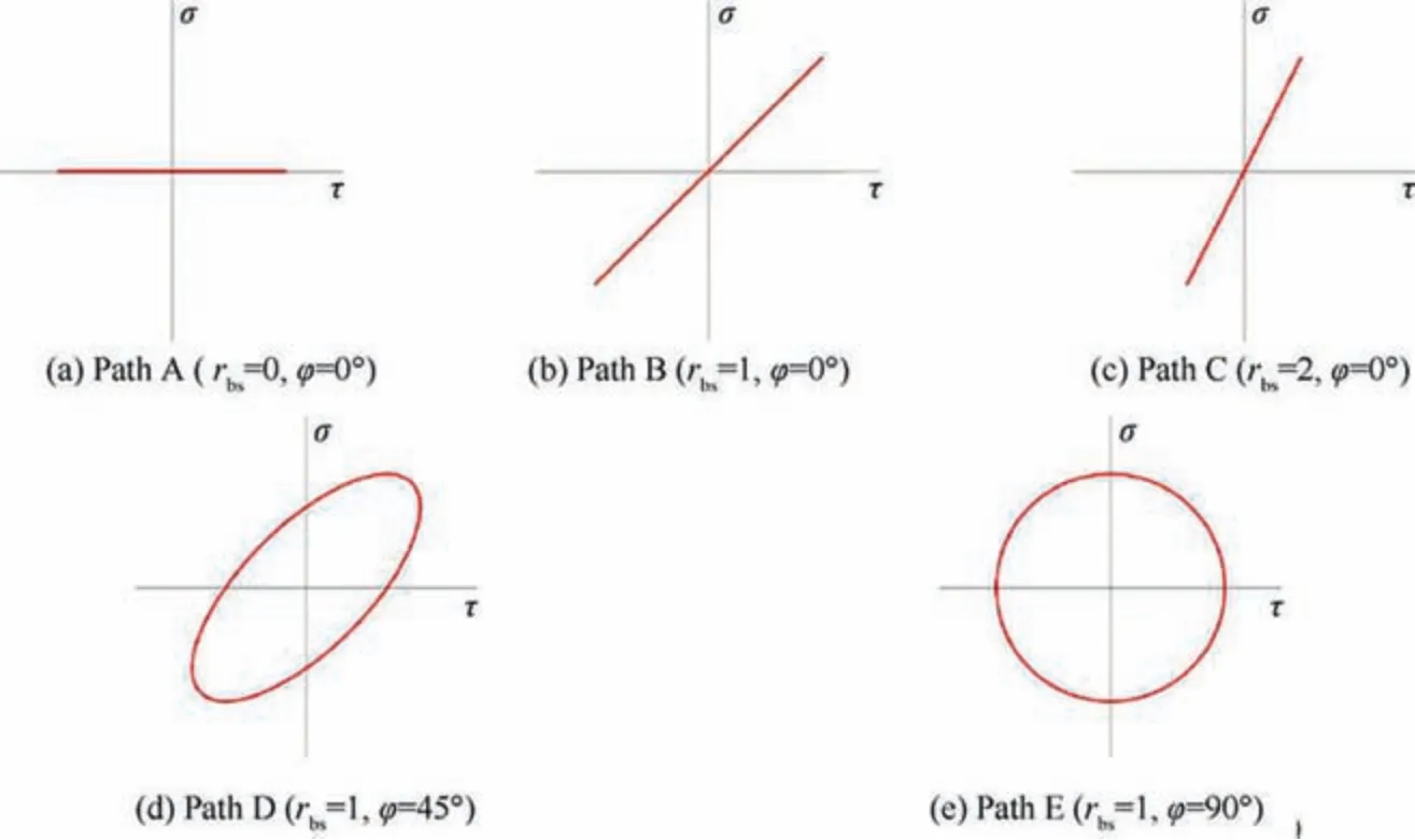
Fig. 6 Tension-torsion biaxial fatigue loading paths of tubular specimen.
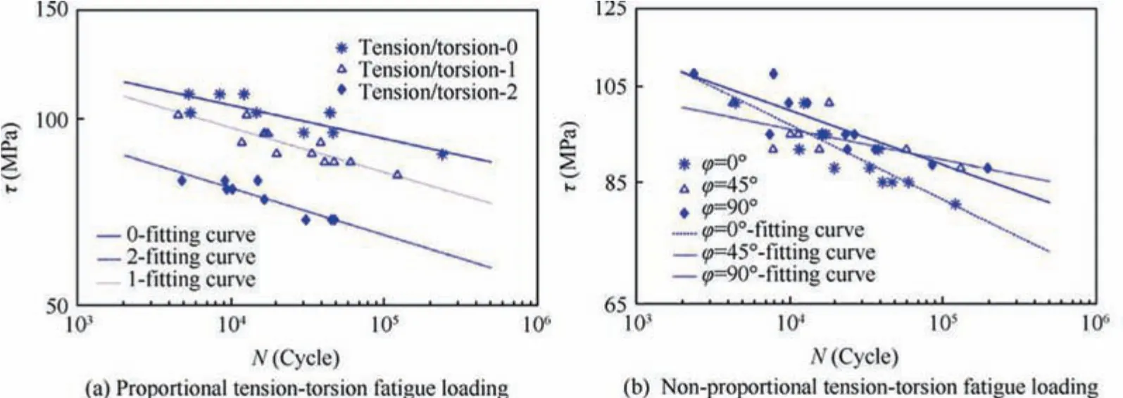
Fig. 7 Maximum stress-fatigue life curves for composite laminates under tension-torsion biaxial loading.

where σais axial stress amplitude, τais torsional stress amplitude, ω is angular frequency, t is time, and φ is phase angle.The biaxial fatigue data for different loading paths are plotted in Fig. 7. Fitting the data by the least square method, it is found that the experimental data can be fitted by straight line in double logarithmic coordinate axis.From Fig.7(a),it can be seen that fatigue lives are strongly dependent upon the biaxial ratio.With increase of biaxial ratio,fatigue lives decrease obviously.While from Fig.7(b),it can be seen that phase angle has less effect on fatigue lives. When fatigue lives are in the range of 2000-30,000, phase angle has little effect on fatigue lives.And with stress level decreases, under the same stress level,the fatigue life of composite laminates under 90° nonproportional loading is longer than 45° non-proportional loading, and the fatigue life of composite laminates under 45° non-proportional loading is longer than proportional loading.
3. Biaxial strength and fatigue life prediction of composite laminates
3.1. Macro-scale 3D RVE
For composite laminates,the strain components in each material principal direction of each layer is different and restricted by the stacking sequence. With periodic boundary conditions,a macro-scale 3D RVE corresponding to composite laminates(Fig. 8, tnis the thickness of the nth layer, and θnis the ply orientation angle of the nth layer) is established to calculate the strain components in each material principal direction of each layer for each biaxial stress ratio.
3.2. Meso-scale 3D RVE
The authors21proposed a new method to generate random distributions of fibers in the transverse cross-section of fiber reinforced composites. Based on microscopy observation of the transverse cross-section of unidirectional composite laminates,this algorithm takes hexagon arrangement as the initial arrangement, assigns a random initial velocity to each fiber,and simulates perfectly elastic collision. With appropriate terminal condition, the RVEs corresponding to unidirectional prepreg with randomly distributed fibers can be adequately generated. Fig. 9 gives an example of generated distribution of fibers in the cross-section. Extruding the fibers and the matrix along the normal direction of transverse cross-section,3D RVE corresponding to each layer with randomly distributed fibers (Fig. 10) can be obtained.
3.3. Prediction of biaxial strength
By applying periodic boundary conditions to macro-scale 3D RVE and adjusting strain components, the equivalent stress components of macro-scale 3D RVE can satisfy each biaxial stress ratio. Establishing meso-scale 3D RVE of each layer and inheriting each strain component from macro-scale 3D RVE of each layer,with progressive damage method,the biaxial strength of composite laminates can be predicted. The meso-scale 3D RVE contains two kinds of materials. Therefore,under external load,the failure of fiber and matrix should be judged simultaneously.
The integrated model to predict biaxial strength of composite laminates consists of three parts:stress analysis, failure criteria and stiffness degradation model.The details of the whole process are presented as follows.
Hashin25proposed a set of famous failure criteria for predicting the failure of fiber at macroscopic. In this paper,Hashin failure criteria of fiber are extended for fiber monofilament as follows.
Tensile fiber failure mode (σ11>0)

where σijis mechanical stress, Xtfand Xcfrepresent the longitudinal tensile and compressive strength of fiber respectively,Xsfis the shear strength of fiber, αTand αcrepresent the contribution factor of shear stress in tensile fiber failure and compressive fiber failure mode respectively.
Since matrix is one kind of isotropic material,energy-based failure criteria are used to judge the failure of matrix.
Tensile matrix failure mode (σ11+σ11+σ11>0)
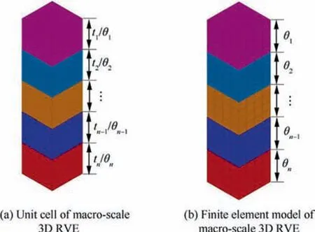
Fig. 8 3D RVE which is corresponding to composite laminates.
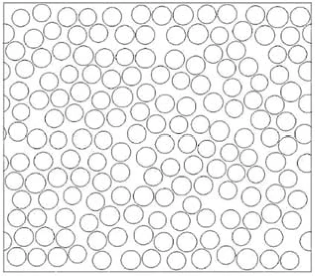
Fig. 9 An example of generated distribution of fibers.
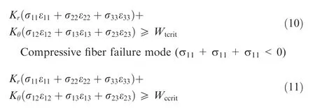
where Krand Kθare the function (Eq.(12), defined in this research) of stress components of Point A as shown in Fig.11(a single fiber is included in infinite matrix,and the area of the fiber divided by the area of the hexagon equals to fiber volume fraction, where R is the radius of the fiber, and or θ is the cylindrical coordinate system). Wtcritand Wccritrepresent the tensile and compressive fracture strain energy respectively(Eq.(13)),and they are obtained from the tensile and compressive properties of resin casting body according to GB/T 2567-2008.
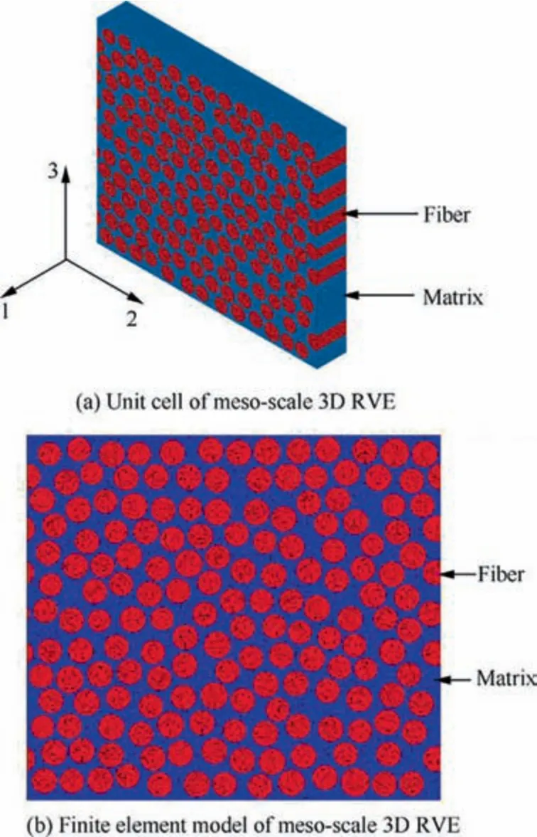
Fig. 10 3D RVE corresponding to each layer with randomly distributed fibers.

Once fiber or matrix element satisfies corresponding failure criteria,the carrying capability will degrade. In this paper,the technique of deactivate and reactivate element is used to realize the degradation of carrying capability of fiber or matrix element. When any element in fiber or matrix domain fails, the degradation factor is 10-6. Once the carrying capacity of all layers reduced by 50%,it can be considered that the composite laminates fails.
3.4. Prediction of biaxial fatigue life
3.4.1. Energy-based fatigue damage parameter
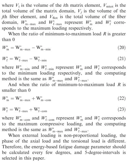
Since composite material is one kind of multiphase material which contains tremendous amount of fibers, the stress field and strain field of fiber and matrix are not uniform and periodic under external biaxial loading. In combination with the meso-scale 3D RVE proposed by the author,21the energybased fatigue damage parameters of matrix and fiber are defined as
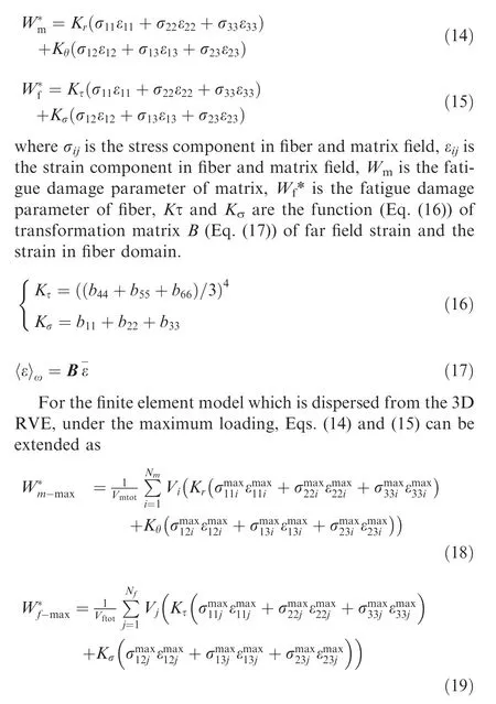
3.4.2. Method of multiaxial fatigue life prediction
The whole method of multiaxial fatigue life prediction contains three parts: part of determining the boundary condition, part of establishing the reference curve and part of predicting biaxial fatigue life.In the part of determining the boundary condition, establish 3D RVE which is corresponding to composite laminates, apply periodic boundary condition, and adjust the strain components to make sure the equivalent stress components satisfy the biaxial stress ratio.In the part of establishing the reference curve,select any one of off-axis angle to establish the equation of W*m- N,and select any one of loading path at which the final failure of composite laminates is fiber failure to establish the equation of W*f - N. In the part of predicting biaxial fatigue life, through 3D RVE which is corresponding to each layer of composite laminates, predict the fatigue life of composite laminates. The detailed procedures are shown in Fig. 12.
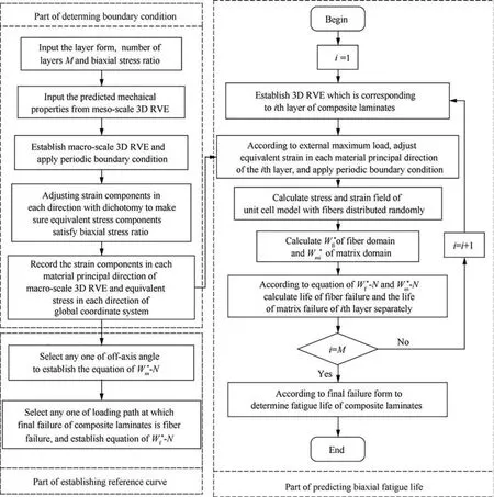
Fig. 12 Flow chart of predicting multiaxial fatigue life.

Table 5 Comparison of predicted off-axis strength and experimental results of unidirectional composite laminates.

Table 6 Comparison of predicted biaxial strength and experimental results of composite laminates.

Fig. 13 W*m - N data for 90° and fitting curve.
In addition,Refs.12,18-19,26have shown that all data fall on a straight line when the fatigue damage parameter is plotted against the fatigue life in a log-log co-ordinate system. This relationship will be verified and used in this paper.
4. Results and discussion
Two sets of experimental data are used to verify the proposed biaxial fatigue life prediction method.One is the data of unidirectional laminates subjected to cyclic off-axis loading,and the other is the data of composite laminates subjected to tensiontorsion biaxial loading.
4.1. Strength prediction
4.1.1. Off-axis strength prediction
Unidirectional T700/epoxy fiber reinforced epoxy laminates at four different fiber load angles have been tested in this paper.With progressive damage prediction method, the strength of unidirectional T700/epoxy composite laminates is predicted.And the results are listed in Table 5. The maximum error is 7.47%.
4.1.2. Tension-torsion strength prediction
With progressive damage prediction method, the multiaxial static strength of composite laminates in the form of[45/70/0/-70/-45] is predicted. The results are listed in Table 6.When the biaxial stress ratio equals to 2, the error between predicted results and the experimental values are around 12%. For other biaxial stress ratios, the maximum error is 5.12%.
4.2. Fatigue life prediction
4.2.1. Off-axis fatigue life prediction
In order to verify the applicability of the proposed method,the fatigue lives of T700/epoxy on four different fiber load angles,namely 30°,45°,60°and 90°have been examined.The ratio of external minimum-to-maximum stress is 0. For all fiber load angles, the failure mode is matrix failure. Therefore, an arbitrary one can be used to predict the fatigue lives of other fiber load angles. Data obtained from 90° are used to establish W*m- N curve (Eq. (24), Fig. 13).

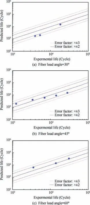
Fig. 14 Comparison of predicted fatigue life and original test data under different fiber load angles.
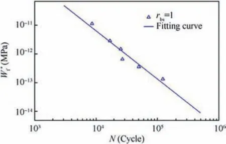
Fig. 15 W*f - N data for loading Path B and fitting curve.
With W*m- N curve of 90°as reference,a comparison of the predicted fatigue lives and experimental results are presented in Fig.14.Predictions and experimental data show good agreement, 82% data of the total predictions lie in two error band(×±2), and 100% data of the total predictions lie in three error band (×±3).
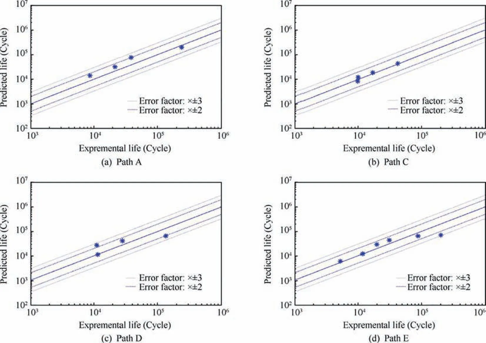
Fig. 16 Comparison of predicted fatigue life and original test data under different loading path.
4.2.2. Tension-torsion fatigue life prediction
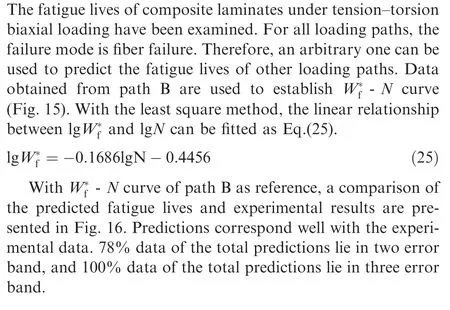
5. Conclusions
In this paper, the multiaxial mechanical behavior and fatigue life prediction model under combined tension-torsion biaxial loading are systematically studied for composite laminates.The experimental investigation of composite laminates has been conducted under tension-torsion biaxial loading. The experimental results show that biaxial stress ratio has an influence on multiaxial fatigue life, while phase angle has little effect on fatigue life.
A macro-meso multiaxial static strength prediction model for composite laminates has been established. One energytype failure criterion was proposed for matrix, and the range of application of Hashin failure criteria has been extended to fiber monofilament. According to the theory of gradual damage propagation, combining the failure criteria of the unit cell of composite laminates, the macro-meso multiaxial static strength prediction model has been established.
A macro-meso multiaxial fatigue life prediction model for composite laminates has been established, which is based on the macro-meso multiaxial static strength prediction model for composite laminates. For the fiber and the matrix, corresponding fatigue damage parameters which considering the effects of stress,strain and loading path were proposed respectively.Combined with damage analysis of composite laminates under multiaxial static loading, the macro-meso multiaxial fatigue life prediction model has been established.
Compared with off-axis experimental results,the maximum error of predicted strength is 7.47%,82%data of the total fatigue life predictions lie in two error band,and 100%data of the total fatigue life predictions lie in three error band.In Comparison with tension-torsion biaxial experimental results, the maximum error of predicted tension-torsion biaxial strength is 12.15%, 78% data of the total fatigue life predictions lie in two error band,and 100%data of the total fatigue life predictions lie in three error band.
Declaration of Competing Interest
The authors declare that they have no known competing financial interests or personal relationships that could have appeared to influence the work reported in this paper.
 CHINESE JOURNAL OF AERONAUTICS2021年12期
- CHINESE JOURNAL OF AERONAUTICS的其它文章
- Entropy based inverse design of aircraft mission success space in system-of-systems confrontation
- Nonlinear resonance characteristics of a dual-rotor system with a local defect on the inner ring of the inter-shaft bearing
- Failure mechanisms of bolted flanges in aero-engine casings subjected to impact loading
- Synchronized perturbation elimination and DOA estimation via signal selection mechanism and parallel deep capsule networks in multipath environment
- Improving seeking precision by utilizing ghost imaging in a semi-active quadrant detection seeker
- A high dynamics algorithm based on steepest ascent method for GNSS receiver
