Dynamic parametric modeling-based model updating strategy of aeroengine casings
Chengwei FEI, Hotin LIU, Sholin LI, Hun LI, Liqing AN,Cheng LU,*
KEYWORDS Aeroengine casings;Correlated mode pair;Model updating;Parametric modeling;Structural dynamics;Uncorrelated modes
Abstract For accurate Finite Element (FE) modeling for the structural dynamics of aeroengine casings, Parametric Modeling-based Model Updating Strategy (PM-MUS) is proposed based on efficient FE parametric modeling and model updating techniques regarding uncorrelated/correlated mode shapes.Casings structure is parametrically modeled by simplifying initial structural FE model and equivalently simulating mechanical characteristics.Uncorrelated modes between FE model and experiment are reasonably handled by adopting an objective function to recognize correct correlated modes pairs.The parametrized FE model is updated to effectively describe structural dynamic characteristics in respect of testing data. The model updating technology is firstly validated by the detailed FE model updating of one fixed-fixed beam structure in light of correlated/uncorrelated mode shapes and measured mode data. The PM-MUS is applied to the FE parametrized model updating of an aeroengine stator system(casings)which is constructed by the proposed parametric modeling approach. As revealed in this study, (A) the updated models by the proposed updating strategy and dynamic test data is accurate, and (B) the uncorrelated modes like close modes can be effectively handled and precisely identify the FE model mode associated the corresponding experimental mode, and (C) parametric modeling can enhance the dynamic modeling updating of complex structure in the accuracy of mode matching.The efforts of this study provide an efficient dynamic model updating strategy (PM-MUS) for aeroengine casings by parametric modeling and experimental test data regarding uncorrelated modes.
1. Introduction
Model is referred as a bridge accessing to engineering from mechanics.As one effective way to evaluate structural dynamic characteristics, Finite Element (FE) modeling and simulation is often applied in structural design. Especially, for the development of products,the FE modeling and simulation can promote market competitiveness by saving time and experimental costs.Therefore, accurate mathematical models are frequently required to predict the dynamic characteristics of engineering structures.Mathematical models can be derived by FE analysis or modal testing.Sometimes,a mathematical model derived by FE analysis is inaccurate for structures due to complex joints,boundary conditions and damping and exact material properties.1For FE model,error is also unavoidable due to uncertain parameters and hypotheses in modeling.2Need for obtaining accurate models have led to the development of model updating technology which aims at reducing the errors presented in an analytical model based on dynamic test data.
In past thirty years, need of high computational accuracy promotes the rapid development of structural dynamic model updating techniques, to reduce parameter error and improve modeling accuracy by evaluating the correlation between analytical response values and experimental(test)values on vibration modes. Then high-fidelity FE models were iteratively obtained.2,3Berman and Flannelly. investigated structural dynamic model updating with experimental mode data.4Collins et al. systematically discussed the FE model updating approach on mass and stiffness matrix by experimental natural frequencies and modes.5Recently, model updating has been front-burner issue in structural dynamics. Model updating techniques were extensively applied in structural systems.1,6,7Friswell and Mottershead. reviewed FE model updating in structural dynamics.1Ahmadian et al. studied parameters selection strategy in FE model updating.8Mares et al. investigated natural frequency error between FE model and experiment.9Marwala and Sibisi developed a FE model updating strategy using Bayesian framework and modal properties.10Modak studied model updating technique considering uncorrelated modes by the FE model updating of a beam.11Zhai et al. also researched FE model updating techniques of complex structures with static experimental data.12,13Wan and Ren discussed stochastic model updating utilizing Bayesian approach and gaussian process model.14Ren and Chen performed FE model updating in structural dynamics based on response surface method.15These works promote the development of structural dynamic model updating technique.
Model updating technology mainly comprises direct methods and iterative methods.Direct methods are defined by onestep procedures to make a minimum change in structural matrices. By this way, the updated model can reproduce its measured natural frequencies and mode shapes.16,17One of the concerns in the direct approaches is inefficient in dealing with some spurious modes of vibration, i.e., spill over phenomenon in model updating.18-20Iterative methods are used to accomplish model updating based on experimentally identified modal data.Various efforts on this method have appeared for model updating.5,21-24Iterative method is concerned due to its good convergence and high updating efficiency.
In most instances, updating parameters and measured data have strong random, and thus, so that are variable associated with additional factors. Currently, stochastic FE model is focused in FE model updating to reflects the variability associated with the test data. Perturbation-based methods were developed regarding test-structure variability.25,26Recently, Fang et al. proposed a model updating process to improve the updating efficiency by decomposing one stochastic updating problem into a series of deterministic ones.27Beck and Goller applied Bayesian method to present a statistical framework for model updating.28,29Mthembu et al. discussed the best FE model updating approach by Bayesian evidence statistics.30Zhai et al. discussed a stochastic model updating strategy based on improved response surface model and Monte Carlo simulation for gas turbine stator system.31
Most of the above works indicate that the iterative method of model updating based on modal data may use incomplete measured modal data to freely select updating parameters.Therefore, the iterative method is more widely employed in updating methods,5,21-24to reduce the difference between FE model and experiment in natural frequencies (mode shapes).However,it is noted that before the computation of this difference, FE model mode shapes corresponding to which experimentally identified mode shapes need to be determined.
Modal Assurance Criterion (MAC)32is used to quantify correlation degree (or correlation coefficient) between an FE model mode shape and an experimentally identified mode shape. A MAC value close to 1 indicates good correlation while a value close to 0 indicates a poor correlation.MAC values between all possible pairs of FE model and experimentally identified modes can be computed and the resulting values can be structured as a MAC matrix. A mode-shape pair with the largest MAC value in each column/row is regarded as Correlated Mode Pair (CMP), which indicates the same mode for a pair of an FE model mode and an experimental mode.
In the stochastic updating of complex structures, mode shape pair might change while the updated parameters change with iteration process.Generally,the correlation of each experiential mode shape with the corresponding FE model mode shape is not uniquely established in the model updating of complex structures. This phenomenon is always induced by the following four reasons. (A) It is possible that an experimental mode shape has more than one FE model mode shapes due to similar MAC values in a tiny range,so that the reliably CMP is difficultly determined. (B) An experimental mode shape often has a high relevance with a specific FE model mode shape, but their absolute MAC value is too small to be indicated as a real correlated pair. (C) It is difficult for experimental modal analysis to establish reliably CMPs when close modes in a structure arise.(D)Many uncorrelated modes might be caused by such large FE modeling error which can produce overlarge difference between the mode shapes gained by the FE model and the mode shapes obtained by a modal test.So far, it has not been found yet that an iterative method of modal data-based model updating can efficaciously handle the above uncorrelated modes simultaneously.
To address the above issues,this paper proposes Parametric Modeling-based Model Updating Strategy(PM-MUS)to deal with uncorrelated modes in above-mentioned situations from two perspectives. One is to develop a new method to accommodate and include information about both correlated and uncorrelated modes in updating, by introducing a new objective function to resolve the first three situations. The other is to apply parametric modeling technology to establish FE model by being equivalent to the mechanical characteristics of bolted joints in complex structures,to improve the modeling accuracy.By the ways,the above forth situations are addressed potentially.
2. Model updating theory
This section discusses an undamped model updating technique when the right (one-to-one) correlation between experimental mode and analytical mode for some modes cannot be identified.
2.1. Model updating using corrected modes
For free undamped vibration,the equation of motion of structure is given by

where T and S indicate mass and stiffness matrix,respectively;x and ¨x denote the vectors of displacement and acceleration at degree of freedom on this model.
In Eq. (1), the solutions of the eigenvalue problem involve eigenvalues λAand eigenvector φApredicted by the FE model of the structure. Similarly, let λEand φEexpress eigenvalues and corresponding eigenvector gained by a modal test. Experimental eigenvectors are often complex and require the updating of an undamped model.1,20Low acceptable level of correlation between eigenvalues and eigenvectors lead to the development of FE model updating. It should be noted that the superscripts or subscripts A and E in variables, vectors and matric represent the FE/analytical and experimental data,respectively.
Assuming the vector of updating parameters u=[u1, u2,......, uNu] for FE model updating where Nuis the number of updating parameters, the eigenvalues and eigenvectors of FE model are taken as the function f of the updating parameters, i.e.,
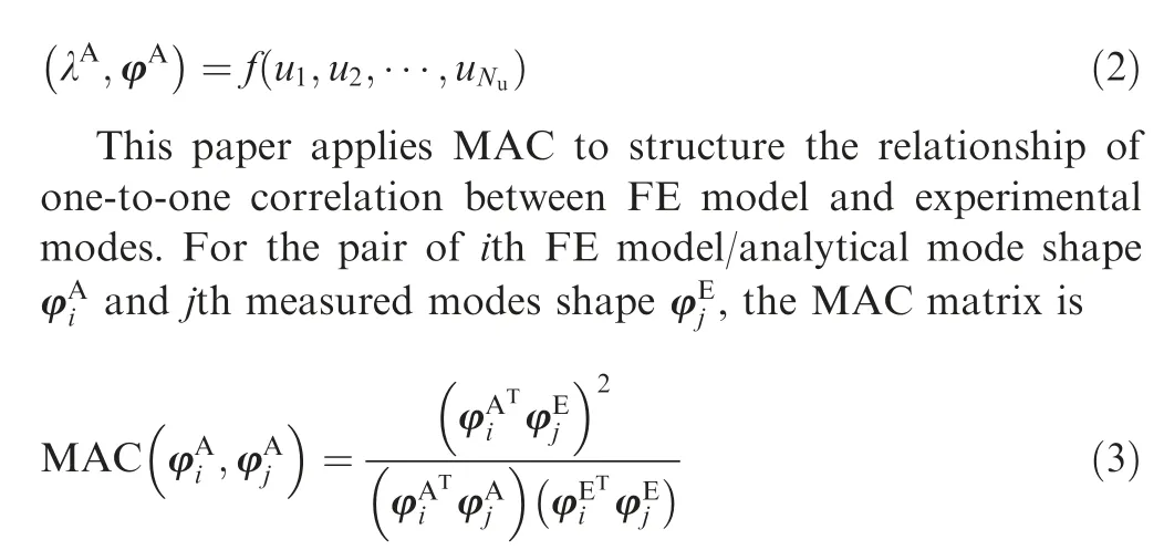
MAC values called mode correlation coefficients indicate the degree of correlation between FE model and experimental modes, which vary in [0, 1]. MAC=1 indicates absolute correlation while MAC=0 denotes zero correlation. Thus, the correlation between the two modes is larger when MAC is closer to 1, and vice versa.32,33MAC is generally a matrix. Reasonable correlation is qualified by all diagonal elements in MAC matrix which are larger than 70%while all nondiagonal elements are less than 10%.33
For use of MAC matrix, erroneous judgment on correlation degree may happen when systemic errors of FE model exist or structure presents local modes.In this case,one experimental mode could be correlated with previous order mode or posterior order mode. It is difficult to correctly judge the correlation for MAC matrix,and easily cause the misled updating of FE model. For the symmetrical structures with repeated roots such as disk,cylinder,and so forth,34-36the MAC values of two similar mode vectors on experiment and analysis/FE model are sometime very small relative to the actual situation.The existing updating methods were based on precise modes in experimental data and did not consider uncorrelated modes.The updating technique requires excessive experiment data to acquire enough correct correlation information, which lead to unbearable time-consuming, human cost and money, especially for costly experiments in aerospace, ship, weapon, and so on. Besides, the updated FE model is inaccurate by only using MAC matrix to identify some distinct correlated data.To address the issues, a novel model updating method is proposed by minimizing an objective function F subject to specific bounds on updating parameters.
2.2. Model updating technique using uncorrelated modes
For updating the model with Uncorrelated Mode Pairs(UMPs) between FE model and experiment, the UMPs are legitimately processed by developing a novel model updating method.
2.2.1. Objective function
In the novel model updating method, the objective function F is defined as
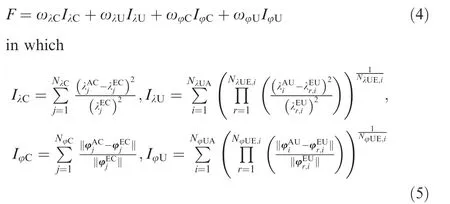
in which Π is the symbol of multiplication; C and U as subscripts and superscripts represent CMPs and UMPs respectively; Subscripts λ and φ indicate eigenvalues and eigenvectors,respectively;IλCand IλUare the percentage errors of FE model eigenvalues against CMPs and UMPs, respectively; IφCand IφUare the percentage errors in FE model eigenvectors against CMPs and UMPs, respectively; ωλC,ωλU, ωφCand ωφUare constant scalar weighting factors of the errors(error functions) IλC, IλU, IφCand IφUrespectively;NλCis the number of eigenvalues corresponding to CMPs applied in F; NλUAdenotes the number of uncorrelated eigenvalues of FE model modes with experimental modes; NλUE,iindicates the number of experimental uncorrelated eigenvalues selected which are considered as possible correlation with the ith analytical/FE model eigenvalue; NφCmeans the number of eigenvectors corresponding to CMPs adopted in the function F; NφUAexpresses the number of uncorrelated eigenvectors of the FE model in F; NφUE,iis the number of experimental uncorrelated eigenvectors chosen for considering possible correlation with the ith analytical/FE model eigenvector.Obviously,the objective function F contains both the correlated and uncorrelated information between FE model modes and experimental modes, i.e., CMPs and UMPs. Lower and upper bounds (ulower, uupper) on updating parameters are regarded as uncertain constrains, i.e.,

The updating parameters vary between lower and upper bounds in Eq.(6),which give out all known information about the maximum degree of variation or uncertainty in the fractional correction factors at the updating stage for obtaining a more meaningful updated model.
From the above analysis, the constrained minimization problem is stated by minimizing the objective function F in Eq.(4),subject to Eq.(6).In this process,the value of u is used to find the updated values of the updating parameters to build the updated FE model. The objective function F in Eq.(4) is elaborated as how to gain a correct estimation of the updating parameters by the minimization of F. Let u* be the vector of updated unknown parameters, the error functions IλCand IφCis zero as u=u*.
2.2.2. Model updating process
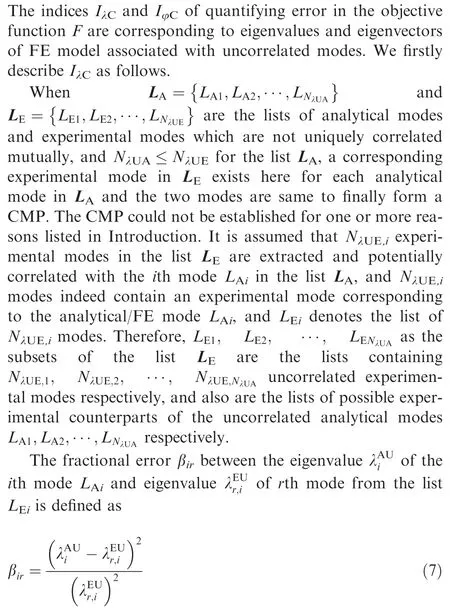
When the rth experimental mode in LEiindeed corresponds to the analytical mode LAi, the error function βiris zero at u=u*, because the two corresponding eigenvalues would be equal at the correct value of the vector of updating parameters.Otherwise, βiris nonzero at u=u*.
For r=1,2,...,NλUE,i, all the error functions {βir} are rewritten as
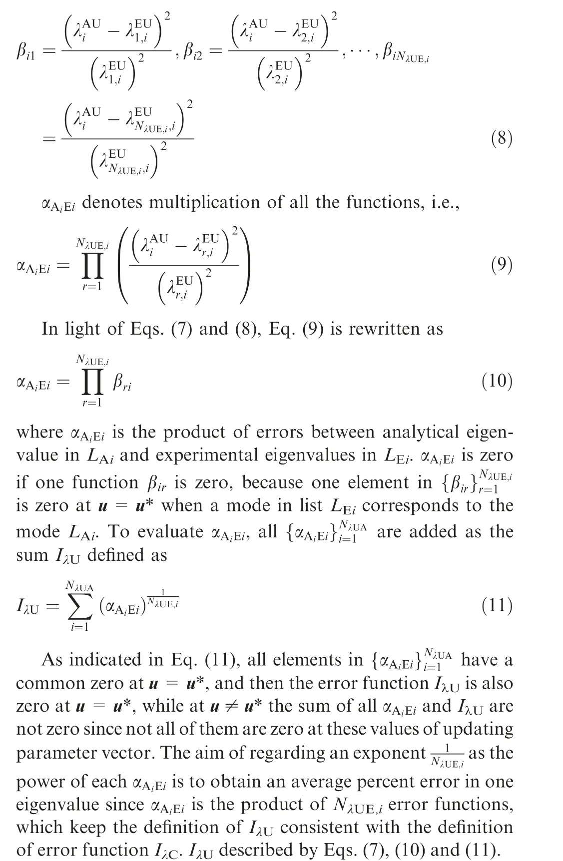
Similar to IλU, the error function IφUmay be also depicted based on the norm of the error between an analytical and an experimental eigenvector. By the same token, IφUis also zero at u=u*.
Based on the above analysis, four error functions IλC, IλU,IφCand IφUmay be discussed. Furthermore, all the functions are zero at u=u*.In this case,the objective function F in Eq.(4) is also zero at u=u*. Obviously, zero is the global minimum value of F since it is always a non-negative function.Thus, the strategy of minimizing the objective function F can successfully achieve the correct value u* of the unknown solution vector u.
From the above analysis,we can find that the model updating strategy considers uncorrelated modes and automatically search for the reliable CMPs, which is promising to improve the effectiveness and precision of model updating. Therefore,the model updating technique regarding uncorrelated modes can enhance the model updating accuracy and make the updated model more match engineering practices.
3. Example
This section regards a simulated beam structure to test the performance of the presented model updating method by updating an FE model and identifying unknown updating parameters.
3.1. Model on beam structure
An undamped FE model of a fixed-fixed beam structure shown in Fig. 1 was considered for updating. Length, width and height on the beam are 1 000 mm, 50 mm and 5 mm.The beam was modeled using six two-nodded beam elements(shown in Fig.2)with lateral and axial displacement and rotation at each node as degrees of freedom.In Fig.2,E1,E2,E3,E4, E5 and E6 indicate the modulus of elasticity of six Fes in simulated beam structure. For the beam, the modulus of elasticity, Poisson ratio and density are 2.0×10¹¹N/m2, 0.3 and 7.8×10³kg/m3, respectively, in the initial FE model that is to be updated.
3.2. Experimental modes
As experimental test structure in Fig.1,certain known discrepancies were introduced in the modulus of elasticity of all FEs as listed in Table 1. Though the analysis of the simulated model, the eigenvalues and corresponding eigenvectors of the model were gained as experimental test or measured data.Six parameters to modulus of elasticity of six FEs were taken as updating parameters,denoted by u1,u2,u3,u4,u5and u6.In the process of updating,the six updating parameters were conducted in the form of fractional correction. As per the simulated errors detailed in Table 1, the correct values of the six updating parameters are shown in Table 2.
Various values on material attribute were given for all beam elements. Three-Dimensional (3-D) FE model of the structure was built as shown in Fig.3.Different color analytical models with the corresponding material property and boundary conditions are equivalent to real structure. For this reason, natural frequencies and modes acquired by calculation are also equivalent to real modes data gained by experimental tests.
3.3. Model updating process
The first three measured eigenvalues and corresponding eigenvectors are considered to perform model updating. For the purpose of validation,the 1st FE model eigenvalue/eigenvector is considered to be correlated with the 1st measured eigenvalue/eigenvector. However, a reliable pairing of the 2nd and 3rd FE model modes is assumed to be obtained abortively,namely, 2nd FE model mode correlates with either 2nd or 3rd measured mode, and 3rd FE model mode correlates with either 2nd or 3rd measured mode as well. Therefore, there is one fact that a definite pairing for some of the FE model modes could not exist, while a mode among measured modes is known to be correlated with a particular FE model mode.37Therefore, the form of a correlation matrix is constructed as given in Table 3.

Fig. 2 Simulated beam structure.
Based on Table 3, mode pair (1A, 1E) is a CMP, while mode pairs {(2A, 2E), (2A, 3E)} and {(3A, 2E), (3A, 3E)}are UMPs, because the actual correlation among them are not confirmed. Therefore, we can gain

Then the updating of beam initial FE model is conducted by minimizing the objective function F described in Eq. (4).The constant scalar weighting factors ωλC, ωλU, ωφCand ωφUare taken unity in all the examples presented. The function F is constructed using both CMPs and UMPs. On the objective function F is now discussed using the numerical example.Thus,the variation of F and its subcomponents with change in updating parameters are studied. Variation with a single updating parameter is first considered. The objective function value is computed by changing this specific updating parameter while holding the correct values of other updating parameters.
Change of IλCand IλUis studied followed by variation of IφCand IφU. For the current example having one such pair in light of correlation matrix in Table 3, the error IλCin the eigenvalues of CMPs is written as

The variation of error function IλCwith modulus of elasticity(u1) of the first FE is gained shown in Fig. 4(a). The minimum value of the error function IλCis zero at u1= -0.1 which is the correct value referencing in Table 2.In this example, we gain

Fig. 1 Beam structure.

Table 1 Elasticity modulus deviation between FE model and simulating experiment.

Table 2 Correct values of updating parameters for FE model.
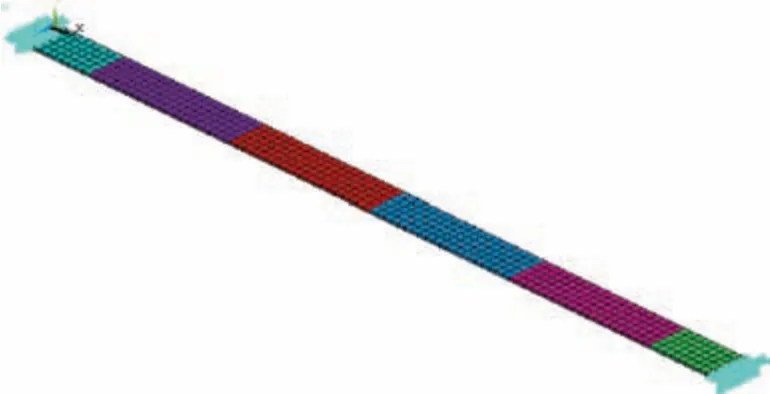
Fig. 3 Simulated experimental FE model of beam structure.

Table 3 Correlation of mode shapes between FE and experiment.
Thus, βirin Eq. (16) is expanded as

By computing β22, β23, β32and β33based on FE model updating on parameter u1varying within[-1,1],the updating results of β22and β23are drawn in Figs.4(b)and(c).Fig.4(d)shows the variation of the function αA2E2=β22×β23with respect to u1
Considering the discussion procedure on the change of the functions β22and β23with updating parameter u1, the variations of β32and β33with u1are drawn in Figs. 5(a) and (b),respectively. Fig. 6 depicts the variation of the function αA3E3=β32×β33with respect to u1. It is found that the function αA3E3has a zero at u1= -0.1 and increases on either side of this point.
In the process of updating,the change of the error function IλUwith u1is depicted in Fig. 6(b). As uncovered in Fig. 6(b),the error function IλUalso has a zero at u1= -0.1 and increases on either side of this point. The phenomenon is due to that the constituting functions αA2E2and αA3E3also have zeros at u1= -0.1.
The above discusses the computational process of the error function IλCand IλU. Similarly, IφCand IφUcan be gained.Then the objective function F is evaluated based on the acquired four error functions(IλC, IλU, IφCand IφU). When the weighted factors are assumed to be unity ‘‘1”, in respect of Eq. (4) the objective function F is

Regarding Eq.(18),the evaluation of the objective function F is shown in Fig. 7. It is seen that the minimize value of the objective function F is zero at u1= -0.1 which is the correct value. However, F is larger when u is other values.
One updating parameter u1in FE mode of beam was updated in detailed and investigated using uncorrelated modes in the above. Similarly, with the modes test data, other five parameters (u2, u3, u4, u5and u6) can be updated. When the objective function F is minimum, the correct values of all updating parameters are achieved in Fig. 8.
To further support the effectiveness of the proposed updating technique,the comparison of the first five natural frequencies before and after updating for the experiment measurement and FE model is shown in Table 4. Herein, MAC values between the corresponding measured and FE model mode shapes are also shown.
3.4. Discussion
It is illustrated in Fig.4(b)that β22has a zero(minimum value)at u1= -0.1 which is the correct value of the updating parameter u1and increases on either side of this point,because the 2nd analytical mode indeed correlates with 2nd measured mode. The function β23in Fig. 4(c) has a positive non-zero value at u1= -0.1 within global range [-1, 1], rather than zero.The reason is that the 2nd analytical mode does not correlate with 3rd measured mode.Besides,β23decreases with rising u1since the 2nd analytical eigenvalue increases and approaches 3rd measured eigenvalue.Fig.4(c)shows variation of the function αA2E2=β22×β23with respect to u1, indicating the product of the plots in Fig.4(b)and(c).It is revealed that the function also reaches at a zero at u1= -0.1 while it increases as u1is not-0.1.
As shown in Fig. 5(b), the function β33reaches to a zero(minimize value) at u1= -0.1 and increases on either side of this point, because 3rd analytical mode and 3rd measured mode are indeed correlative. However, function β32in Fig. 4(a) has a positive non-zero value at u1= -0.1 since 3rd analytical mode does not correlate with 2nd measured mode.Meanwhile, β32increases with the increase of u1because the 3rd analytical eigenvalue increases away from the 2nd measured eigenvalue.
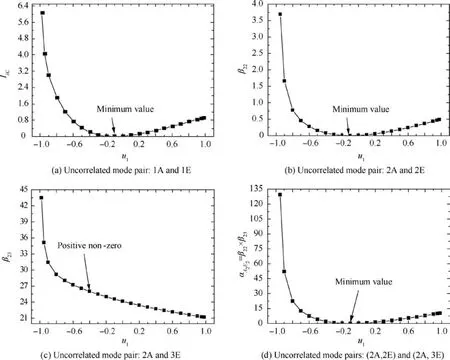
Fig. 4 Variations of functions with updating parameter u1.
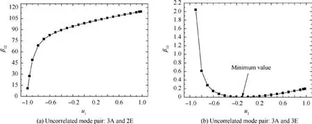
Fig. 5 Variations of functions β32 and β33 with updating parameter u1.
As indicated in Figs.4-6,the function αA2E2=β22×β23has a zero at the correct value of the updating parameter u1since β22has a zero at this point even though β23does not have zero.If 2nd analytical mode finally correlates with 3rd measured mode,β23would have a zero at the correct value of the updating parameter u1. In this case, the function αA2E2would still have a zero at the correct value of u1even though β22does not have. It is important for this conclusion because the minimization process automatically tend to form a pair of the modes which is correlated actually,namely,the error functions αA2E2and αA3E3are convergent. In other words, when the correlation of FE model modes with experimental modes cannot qualified,the correlated and uncorrelated modes in experimental modes with respect to analytical/FE model modes can be automatically identified by the term βirin the objective function F. Therefore, updating of model should be performed even when the correct pairing of modes from the two sets of data is unknown.
As indicated in the analysis on the objective function F with parameter u1(in Fig. 7), all the functions IλC, IλU, IφCand IφUcomposing the objective function F have a zero at the correct values of the updating parameters u1,leading to that F also has a similar behavior. Therefore, the minimization (zero) of F, a non-negative function, can indeed find the correct values of the updating parameters u1.
As illustrated in Fig. 8, all the updating results are consistent with the data in Table 2, which demonstrates the correctness and efficiency of the results from processing uncorrelated modes for model updating.
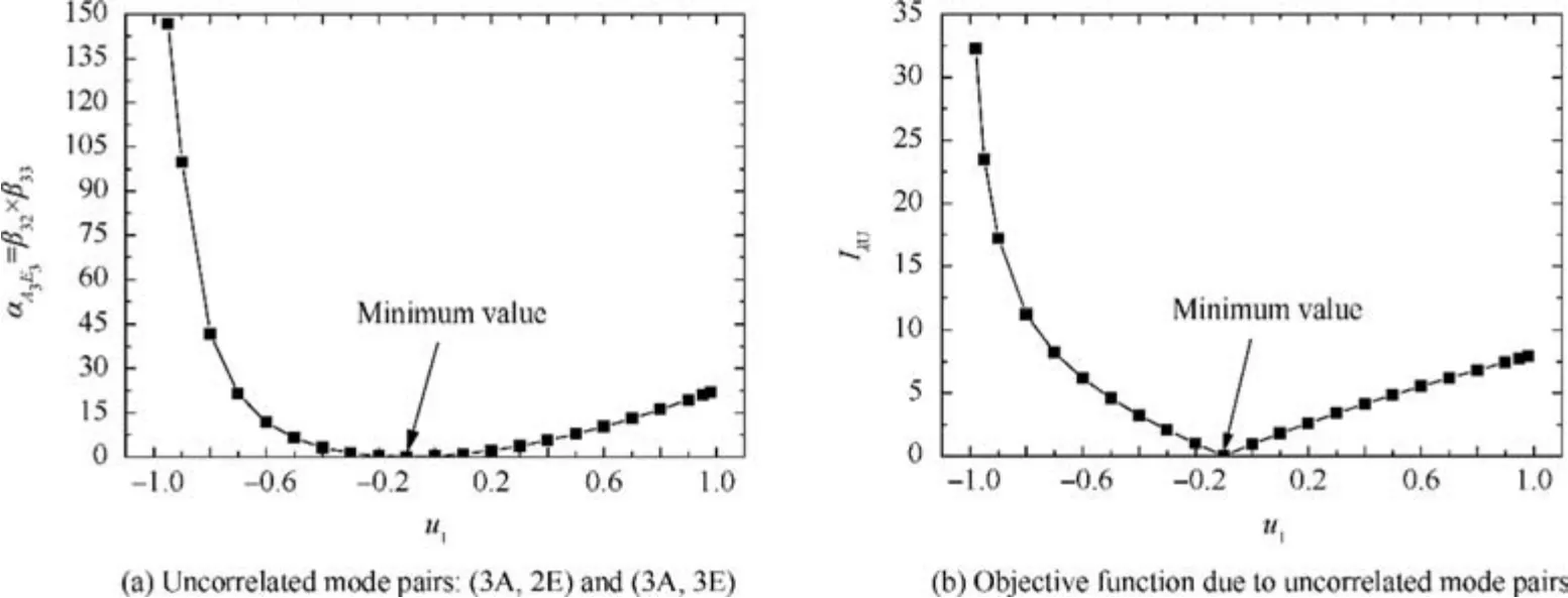
Fig. 6 Variation of functions αA3E3 and IλU with updating parameter u1.
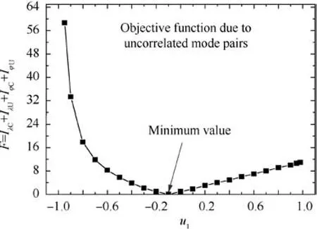
Fig. 7 Variation of objective function F with parameter u1.
As revealed in Table 4, natural frequencies and MAC values show a good correlation for the updated model, not only for the modes used in updating (first three modes shown in shade) but also for those not used in updating. A MAC value 1.0 for 2nd and 3rd modes indicate that the model updating method has automatically chosen the correct CMPs, because the correlation for these modes was assumed to be unknown and treated as uncorrelated modes.
Therefore, the proposed updating method is efficient and precise in FE model updating with CMPs and UMPs. The upcoming section is to adopt the proposed updating technique to perform the model updating of complex structure (stator casings system of an aeroengine) with parametric modeling based on thin-layer element method.
4. Model updating for complex structure
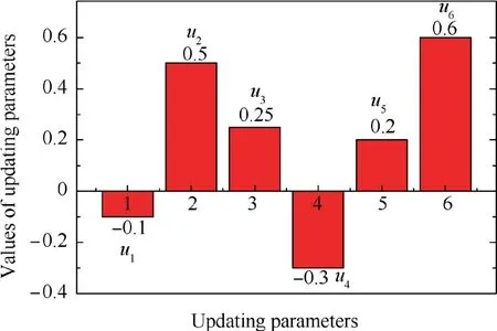
Fig. 8 Values of updated parameters.
In this section, we apply the proposed model updating technique and parametric modeling method to conduct the FE model updating of an advanced turbofan engine stator system(casings) by considering uncorrelated and correlated modes as well as test data. The engineering background on the model updating of the stator system is firstly introduced with the emphasis on the mechanical characteristics of the casings. Then parametric FE model of the casings is built by simplifying bolted joint structures with respect to the equivalent simulation of mechanical characteristics.

Table 4 Experimental and FE model natural frequencies before and after updating.
4.1. Characteristics analysis of casing structure
As an important structure system of an aeroengine. The dynamic characteristics of the casings severely influence critical speed of rotor and dynamic characteristics of aeroengine.38FE modeling of casings is always disturbed by some uncertainty factors and thus has some model error.39Especially, it is difficult to efficaciously simulate the real mechanical features of joint structures by the equivalent simulation and modeling methods of jointed components to reduce error between FE model and real structure model, because the intrinsic frequencies and mode shapes of FE model always deviate from and mismatch with the real values of structures. How to establish precise FE model of bolted joints in aeroengine casings is one key issue in the aspect of FE modeling of the casings.
Posteriorly, stator system(casings) of an aeroengine is typical thin-walled cylinder structure with complicated modes like close mode. For the close modes, it is difficult to quantify the correlation of experimental modes with the corresponding FE modes.40Besides, available updating techniques of structural FE model are based on experimental test natural frequencies and mode shapes in structural model updating. When close modes exist,however,the methods are unworkable to quantify the correlation of test modes with FE model modes, so that it is hard to meet the accuracy of stator casings FE model.
To build the efficient and accurate FE model of aeroengine casings, the above issues are addressed by two aspects. One focuses on FE modeling of the casings. Hereinto, the thinlayer element method13,31,41is adopted to build the parametric model of bolted joints by the equivalent mechanical characteristics of bolted joint structures in the casings. Then the parametric model instead of the initial FE model on bolted joints is used in the FE modeling of the casings. The other is FE updating of the structure (casings). FE model of casings is updated based on the developed model updating technique in respect of both correlated and uncorrelated modes as well as valid test data. Namely, in the updating of model, the correlated and uncorrelated modes information between experiment and FE analyses in the structure of objective function are esteemed. Therefore, it is promising to improve the precision of FE model updating for casings structure based on the proposed PM-MUS.
4.2. Parametric FE model
The stator system(casings) comprises intermediate casing,composite external duct (bypass), bearing outer casing and augmented casing.These components are connected by bolted joints.The initial FE model of the casings with 49 152 elements and 91 485 nodes was established as shown in Fig.9.Therein,three directions on main installation section are restrained and one direction on rear auxiliary installation section is constrained.
The bolted joints of an aeroengine stator structure bear the loads of tensile force, pressure force and beading force,because shear load is transformed into rubbing effect and fasten among flange contact surfaces.41Due to existence of bolted joints,it is difficult for the FE modeling of casing and dynamic analysis. In this study, the initial FE model is simplified by simulating the mechanical characteristics of bolted joint structures through parametric modeling with thin-layer elements method.13,31The parametrized FE model of casings is displayed in Fig. 10, including the parametric model of bolted joint structures and the FE model of casings without bolted joint structures.Herein,the corresponding nodes to each other on contact surface(area)for bolted joints are radially coupled to generate large shear stiffness.Then these parts are contacted by introducing axial thin-layer element into the reciprocally corresponding nodes, to simulate the mechanical characteristics of bolted joints among intermediate casing, composite external duct (bypass), bearing outer casing, and augmented casing.
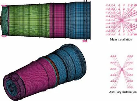
Fig. 9 Initial FE model of stator system(casings).
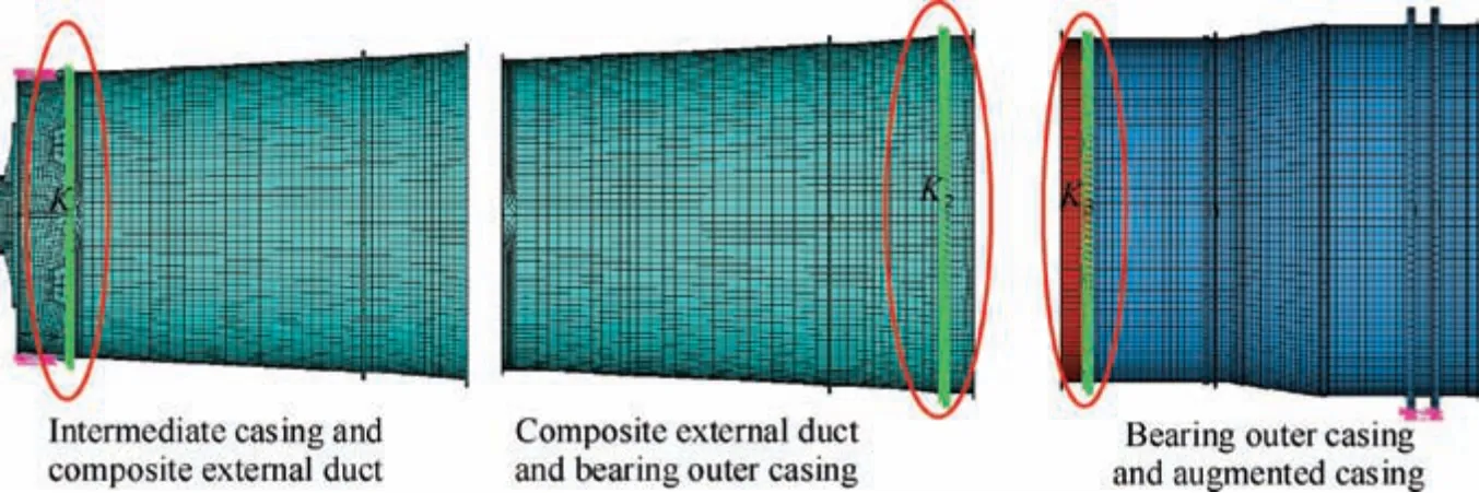
Fig. 10 Parametric FE models of casings with bolted joints.
4.3. Model updating
Based on the parametric FE model of the casings and engineering experience, the locations of bolted joints are regarded as the error sources of modeling,and the stiffness of bolted joints in casings are taken as K1=2.3×10⁸N/m, K2=1.5×10⁸N/m and K3=1.0×10⁸N/m, respectively. Though the experiment and FE analysis, the first twelve natural frequencies of the casings are achieved in Table 5. Besides, the MAC matrix between FE model modes and experimental modes is drawn in Table 6. From the above analysis, based on the FE model updating of the casings with dynamic model updating technique, the maximum MAC values for both FE model modes and experimental modes is listed in Table 7. Meanwhile, the analytical results of the correlation between FE model modes and experimental modes are illustrated in Table 8. It should be noted that all experimental data came from the dynamic test of an advanced aeroengine which is conducted in an aero-engine research institute of China,and the details on the experiment did not give due to the limitation of confidentiality.

Table 5 Natural frequencies from parametric FE analysis and experimental test of the casings.
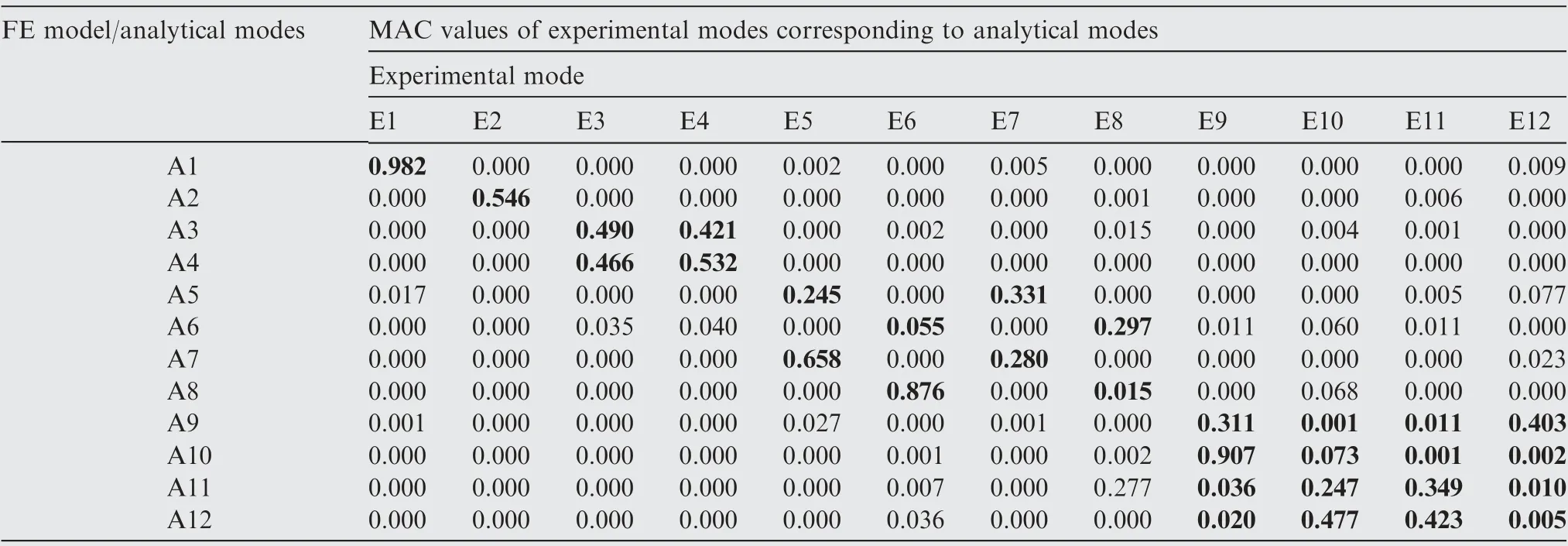
Table 6 MAC matrix between experimental and FE model modes.
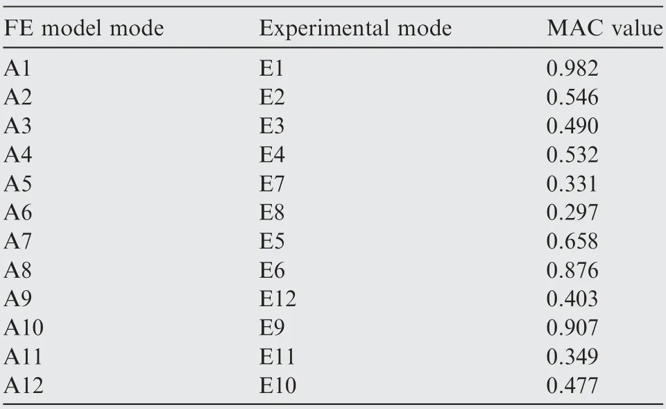
Table 7 The maximum MAC values between experimental and FE model modes.
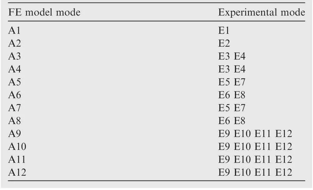
Table 8 Correlation between FE model modes and experimental modes.
To address this issue, via the developed model updating technique, the FE model updating of the casings is executed by the measured data as well as CMPs and UMPs gained from the above analyses. The results before and after updating are shown in Table 9.
5. Discussion
As illustrated for the casings in Table 5, the error rises for the twelve modes obtained by experiment and FE model analysis with maximum error 22.7%, minimum error 3% and average error 8.65%, which indicate large deviation for the FE model from real structure so that the FE model cannot be applied to the analysis and design of the casings replacing real structure.This is the reason why the updating of FE model needs be done to cater for experiments.
As revealed in Tables 6 and 7, the modes gained by FE model hold large deviation from the corresponding experimental modes.Namely,the FE model modes belonging to the corresponding test modes have obvious errors after FE model updating based on the traditional method and experimental data. For instance, 5th FE model mode has maximum MAC value 0.331 with 7th measured mode rather than 5th measured mode, and 7th analytical mode has maximum MAC value 0.658 with 5th experimental mode rather than 7th experimental mode, and so forth. Therefore, the initial parametric FE model is not too accurate to reflect the dynamic characteristics of the casings. In other words, it is inefficacious only by FE model and test data to ascertain the correlation of FE model modes and experimental modes based on model updating due to ignore the processing of uncorrelated modes.
As seen in Table 8,although the correlation on 1st and 2nd modes of FE model/analytical and experiment can be identified, the correlation on other modes is unsuccessfully recognized, and close modes appears from 3rd mode to 12th mode because one FE model/analytical mode is related with various experimental modes. Therefore, it is urgent to update the initial FE model of casings structure based on experimental test data and thus promote the accuracy of FE model established.
As demonstrated in Table 9, the natural frequencies and modes of the updated FE model are almost consistent with these of experimental test, and thus the updated FE model get a large improvement. This reason is that all the errors of natural frequencies of FE model are less than 3% referencing the natural frequencies measured from experiments,so that all the MAC values of CMPs between FE mode and experiment are 1. In other words, the proposed updating strategy indeedeffectively make FE model modes match experimental modes by processing close modes measured and other uncorrelated modes. It is demonstrated that the presented PM-MUS with uncorrelated modes has high accuracy and is likely to gain a high-fidelity FE model of an aeroengine casings(stator system)for dynamic analysis and health monitoring.
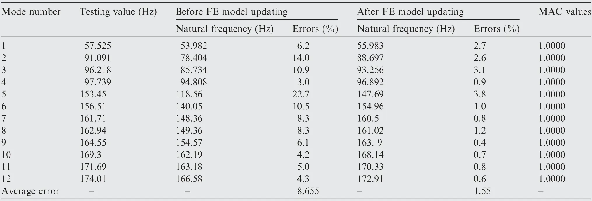
Table 9 Results before and after FE model updating via the proposed method.
6. Conclusions
The aim of this study is to propose Parametric Modeling-based Model Updating Strategy (PM-MUS) to deal with uncorrelated mode shapes of dynamic model updating of aeroengine casings, by adopting parametric modeling to be equivalent to the mechanical characteristics of structures. Model updating using uncorrelated modes was discussed at detail by introducing an objective function. The developed dynamic model updating technique was validated by the FE model updating of a fixed-fixed beam structure and then was employed to perform the FE model updating of the casings (stator system) of an advanced aeroengine. The conclusions are summarized as follows:
Through FE model updating of a fixed-fixed beam structure, we find that the proposed model updating technique can effectively handle uncorrelated modes and automatically identify the correct Correlated Mode Pairs (CMPs) in model updating by introducing an objective function. The proposed model updating method is likely to address the difficulties of identifying correct CMPs in structural dynamic model updating, and be also used in structural dynamic model updating of complex structures.
As illustrated in FE model updating of an aeroengine casings, the presented PM-MUS can make natural frequencies and modes between the updated FE model and experimental measure very close, so that the updated FE model get a large improvement. The presented model updating technology with uncorrelated modes has high accuracy for MAC=0 and tiny errors for modes between test mode data and the updated FE model by regarding corelated and uncorrelated modes. The results are likely to build a high-fidelity FE model of an aeroengine casings (stator system) and many apply the updated model instead of true structure to the dynamic analysis and health monitoring of an aeroengine. Besides, parametric modeling is also an efficient tool to enhance the model updating of complex structures, by regarding equivalent simulation of mechanical characteristics of bolted joints.
The efforts of this study offer an efficient model updating strategy (PM-MUS), which integrates an efficient model updating technique proposed and parametric modeling method, to establish accurate and reliable FE model for the complex structures of aeroengine stator casings. Thereby, it is possible for the model-based analysis and design of complex structures to largely reduce plenty of time lapse, costs and manpower.
Declaration of Competing Interest
The authors declare that they have no known competing financial interests or personal relationships that could have appeared to influence the work reported in this paper.
Acknowledgements
This study was co-supported by National Natural Science Foundation of China (Nos. 51975124 and 51675179), Shanghai International Cooperation Project of One Belt and One Road of China(No.20110741700)and Research Startup Fund of Fudan University(No.FDU38341).The authors would like to thank them.
 CHINESE JOURNAL OF AERONAUTICS2021年12期
- CHINESE JOURNAL OF AERONAUTICS的其它文章
- Entropy based inverse design of aircraft mission success space in system-of-systems confrontation
- Nonlinear resonance characteristics of a dual-rotor system with a local defect on the inner ring of the inter-shaft bearing
- Failure mechanisms of bolted flanges in aero-engine casings subjected to impact loading
- Synchronized perturbation elimination and DOA estimation via signal selection mechanism and parallel deep capsule networks in multipath environment
- Improving seeking precision by utilizing ghost imaging in a semi-active quadrant detection seeker
- A high dynamics algorithm based on steepest ascent method for GNSS receiver
