A novel model-based multivariable framework for aircraft gas turbine engine limit protection control
Shuwei PANG, Soheil JAFARI , Theoklis NIKOLAIDIS Qiuhong LI
a Jiangsu Province Key Laboratory of Aerospace Power System, Nanjing University of Aeronautics and Astronautics,Nanjing 210016, China
b Propulsion Engineering Center,School of Aerospace,Transport and Manufacturing,Cranfield University,Bedford MK43 0AL,UK
KEYWORDS Amplitude conversion;Command reconstruction;Gas turbine engine;Limit protection control;Multivariable control;Onboard prediction
Abstract Control technologies are innovated to satisfy increasingly complicated control demands of gas turbine engines.In terms of limit protection control,a novel model-based multivariable limit protection control method, which is achieved by adaptive command reconstruction and multiplecontrol loop selection and switch logic,is proposed in this paper to address the problem of balancing smaller thrust loss and safe operations by comparing with widely-used Min-Max logic.Five different combination modes of control loops, which represent the online control loop of last time instant and that of current time instant, is analyzed. Different command reconstructions are designed for these modes, which is based on static gain conversion of amplitude beyond limits by using an onboard model. The double-prediction based control loop selection and switch logic is developed to choose a control loop appropriately by comparing converted amplitude beyond limits regardless of one or more parameters tending to exceed limits. The proposed method is implemented in a twin-spool turbofan engine to achieve limit protection with direct thrust control,and the loss of thrust is improved by about 30% in comparison with the loss of thrust caused by Min-Max logic when limit protection control is activated, which demonstrates the effectiveness of the proposed method.
1. Introduction
Gas Turbine Engines(GTEs)are the main power source of an airplane, and robustness, flexibility, and performance are required to be improved for engines of the next generation.Thus, innovations of existing control technologies are motivated to cope with the increasingly complicated control requirements for GTEs.1-3The traditional control architecture that is an indirect thrust control based on sensors has been reported to be conservative because of the controlled variable and the fact that a pre-defined design margin should be kept.4-6 As a result, the novel concept of Model-Based Control(MBC) is proposed to replace the traditional control method,in which an onboard model is used to estimate unmeasurable parameters such as thrust and Turbine Inlet Temperature(TIT),and these estimations are fed back to the control system to achieve direct thrust control.1,7-11
From the view of control, the control system needs to ensure that the engine can gain a balance between better performance and acceptable operability, which means that the engine should not only meet the requirements of flight missions but also operate safely to prevent the occurrence of dangerous accidents.12,13The latter demand is known as limit protection control, which imposes various restrictions on the engine during the operation, such as the maximum speed, the maximum turbine inlet temperature and so on,and the real-time monitor for related parameters is conducted to determine whether these limits will be triggered.14,15The limit protection control is activated to force the engine to operate on or within limit boundaries when one or more limited parameters tend to go beyond limits. In traditional control architecture, different limitations are imposed on measurable parameters to realize an indirect limit of some unmeasurable parameters. However, the direct limit management can be available in model-based control.For example,Model Predictive Control(MPC)is implemented to manage the limitations of parameters online by solving an optimization problem with constraints that represent various restrictions of parameters.14,16-22Unfortunately, a large amount of computation burden is always required by these optimization-based methods, which is uneasy to be implemented in current control systems of GTEs.In contrast,traditional control methods based on Min-Max structure, which gives control signals based on pre-designed controller gains,are extended simply to applications of MBC by replacing limited parameters with estimations of unmeasurable parameters.7,8,10
Min-Max control framework is the most popular one for the limit protection control, of which selection logic is simple and easy to be understood, so it has been widely implemented in GTEs control systems.23,24Every measurable limited parameter is monitored and compared with its limit in realtime, and a control signal, i.e. fuel flow, is calculated by a related control loop.Then,the case that parameters go beyond their limits is avoided by selecting a suitable fuel flow signal based on the minimum and maximum operation. However,this structure is only compatible with single-variable controllers rather than multivariable controllers, because it requires a comparison between different control signals given by different control loops. However, other controllable variables, such as nozzle area, Inlet Guide Vane (IGV) and so on, can only be set in open-loop feature. Consequently, the benefits of multiple control variables being adjusted simultaneously are not considered. Besides that, for the conservative property of Min-Max logic, many methods have been studied to improve it, however, these improvements still focus on single-variable limiter.16,25-28
Indeed, multivariable control, in which multiple controllable variables are controlled at the same time, has attracted high attention in the field of GTE control with the development of Full Authority Digital Electronic Controller(FADEC). Multivariable control methods have been well developed, and many controllers like Hinfcontroller, Linear Quadratic Regulator (LQR) controller, Linear Quadratic Gaussian/Loop Transfer Recovery (LQG/LTR) controller have been studied, which indicates that multivariable controllers have a considerable application prospect in engine control.29-34Thus, multivariable control should be taken into account to make the engine operate as anticipated as possible when limit protection control is triggered.Although multivariable control is considered based on the optimization framework, it is not practical because of the huge computational power requested.14,16,35-37However, attention is not paid enough to implementing multivariable control to improve the limit protection control in traditional control architecture,namely not based on optimization.
In addition, as the fact that the command designed for MBC is not as conservative as the traditional control concept,it is more possible for an engine to reach the limit lines.When large degradations of engine occur, the increase of some parameters, such as low-pressure shaft speed, engine temperature,cannot be avoided because of the attempt to maintain the engine thrust level.4,7-10,17,22,38-42As a result, steady-state violation is caused usually, which means the operating points defined by commands cannot be reached unless the engine operates beyond limits. However, destructive influence may be made if the engine is forced to reach these operating points at the expense of breaking limitations. The issue of command mismatch caused by steady-state violation does not exist in Min-Max logic because only a one-dimensional command is required for a single-variable controller. However, it makes sense in multivariable controllers because their commands are coupled high-dimensional vectors,and unreasonable operating points defined by improper command combinations cannot be reached even with a perfectly-designed multivariable controller, which suggests that model-based limit protection control should have the capability to adjust the command to avoid command mismatch.
Therefore, a model-based limit protection control method for multivariable control is proposed in this paper,which realizes the limit protection control by adaptive command reconstruction and control loop switch. The biggest benefit of the proposed framework is that controller commands are reconstructed and modified adaptively based on static gains that are calculated by state-space models provided by linearizing an onboard model every sampling period. Based on analysis on different combination modes of control loops, which indicates what the online control loop of last time instant and that of current time instant are, different command reconstruction approaches are designed. Besides that, thrust is considered as the most important controlled variable,thus the multivariable control loop can not only control limited parameters but also control thrust at the same time. Furthermore, the case that multiple limited parameters exceed their limits at the same sampling period is also considered, and the limit protection control is realized by controlling thrust and the limited parameter that exceeds its limit most seriously based on a comparison of converted amplitude beyond limits. Also, bumpless switch among different control loops is achieved by introducing a controller-reset strategy based on augmented linear quadratic regulator’s principles, which dismisses complex compensator logic.
In summarize,the main contributions of this paper are:(A)proposing a control framework for the multivariable limit protection control system, and the thrust is always a controlled variable of either the main control loop or limit protection loop, which means that direct thrust control is achieved all the time; (B) presenting an adaptive command reconstruction method to modify the given thrust command automatically in order to achieve a match of thrust command and commands of other parameters in a multivariable control loop; (C)achieving a smaller thrust loss in comparison with Min-Max logic when limit protection control is activated.
The proposed method for limit protection control can be considered as an extension of Min-Max logic to some extent.This is because Min-Max logic can be recognized as a multiple control loop switch logic while the similar switch logic is also conducted in the proposed method.The static gain conversion based command reconstruction method is proposed to generate a reasonable command vector, which makes full use of the onboard model, but it is worthwhile to mention that the reconstructed command may not be the optimal commands.Besides that, it is still necessary to fine-tune the controllers’parameters to achieve an acceptable control outcome because traditional controllers, in which many gains are implemented to calculate control signals, are used in the proposed method.
The paper is organized as follows.Section 1 gives the introduction, and Section 2 describes the proposed framework.LQR based multivariable controller is given in Section 3 while Section 4 and Section 5 describe the core parts of the proposed framework, namely control loop selection module and command reconstruction method respectively. Section 6 gives the information about simulation results and Section 7 concludes the paper.
2. Proposed framework
The innovative multivariable framework for limit protection control,which is comprised of multivariable controllers,a control loop switch logic and a command reconstruction module,is shown in Fig. 1, where r and rlim,iare commands from control schedules, yL,0and yL,iare controlled variables, x is the state, u is the control signal, and Y is the engine output.
Fig. 1 shows the layout of the proposed framework, which operates based on command reconstruction and control loop switch. It contains the main control loop and multiple limit protection loops, the former loop aims at achieving main control objectives with the main controller while the latter provides multivariable limit protection control, in which the controller-reset strategy is embedded to ensure bumpless switch. A control loop selection module is implemented to decide when and how the switch among different control loops(i.e. different controllers) happens. Through this module, a control loop is delegated to be the online control loop to control the engine, while the rest of control loops are allocated to be offline control loops of which outputs are not sent to the engine.Also,an onboard model is introduced to not only provide estimations of unmeasurable parameters as control feedback, including thrust, TIT, surge margin and so on, but also realizes online predictions of certain parameters that are used in the selection and switch logic.Furthermore,it provides static gains that are used to realize adaptive command reconstruction.
Adaptive command reconstruction is one of the most important parts of the proposed framework. Generally, the command of set-point is fed into the main control loop to calculate the control signals, and boundaries of limited parameters are used by limit protection controllers. However, in the proposed framework, man-made commands are not fed to the corresponding control loop directly, instead, they are sent into a command reconstruction module that uses these commands and predictions to reconstruct commands according to different combination modes of control loops.Then,reconstructed commands are given to control the engine by the online control loop.At the same time,all the offline controllers are updated by a simple controller-reset strategy, so their outputs are driven to equal the online controller’s outputs either during the transient operation or at steady-state.
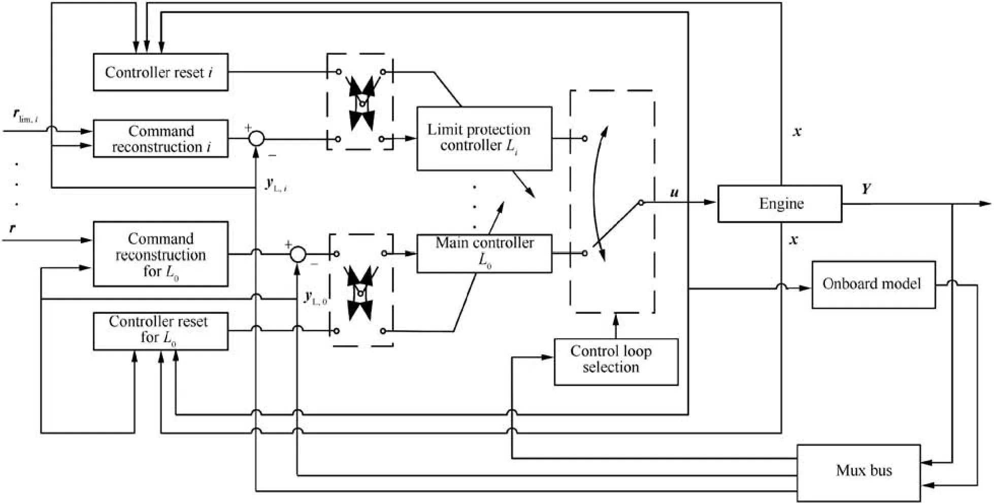
Fig. 1 Layout of proposed multivariable framework.
The control loop selection and switch module plays another key role to activate the appropriate control loop. Aiming at achieving limit protection control, whether these parameters will go beyond limits is evaluated based on a prediction module and a judgment module. As a result, the limit protection loop related to the limited parameter that is predicted to exceed the limit most seriously is activated as the online control loop,and the reconstructed command is fed into the online control loop. Otherwise, the main control loop is activated to control the engine.
An onboard nonlinear model is implemented to provide not only estimations of unmeasurable parameters but also statespace models by linearization, and the state-space model is used to predict parameter changes over next few sampling periods in the prediction module and calculate static gains that are used in command reconstruction module. It is worthwhile to mention that the onboard model is assumed to track the engine well, and then the module to update the onboard model is omitted because the research objective is to realize multivariable limit protection control rather than to improve the onboard model’s accuracy of tracking the engine operation.The control signals that are used to control the engine are also received by the onboard model at the same time,and the state of the onboard model is updated by this control signal.
Fig. 2 shows the flowchart of the proposed method, which denotes the procedure of control loop selection and switch,command reconstruction, and engine control at time instant k. For every sampling period, the assumption that the online control loop of current time instant is the main control loop is made first regardless of which loop is online at time instant k-1,and the command are constructed according to the corresponding control loop combination mode. Then, the closedloop prediction is conducted with the main control loop, and the evaluation of excess of limits is conducted to decide whether the main control loop can be the target control loop based on whether predictions are going beyond limits if it is controlled by the main control loop. The similar closed-loop prediction process and evaluation are conducted with the online control loop of time instant k - 1, which decides whether the online loop should be maintained or switched to another limit protection loop. After that, the target control loop is activated and the reconstructed command is used to control the engine under this control loop. Finally,all the offline control loops’ controllers are reset and control signals are used to control engine behaviors. It is worthwhile to mention that the first-time output prediction is essential for the system to withdraw from the limit protection mode.
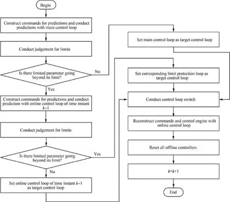
Fig. 2 Flow chart of proposed limit protection method.
3. LQR based multivariable controller
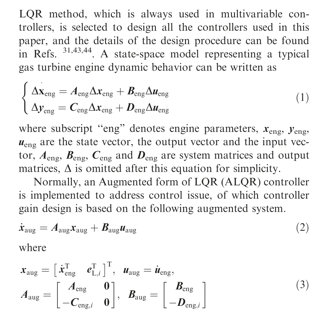
where the subscript ‘‘i” denotes the index of different controllers,the main controller is numbered as 0 and limit protection controllers are numbered from 1 to N respectively.N is the number of limit protection controllers, and it also denotes N limit protection loops. Subscript ‘‘L” denotes the controller parameter. Ceng,iand Deng,iare components of Cengand Dengrelated to the outputs controlled by the ith controller. eL,iis the control error defined as follow.
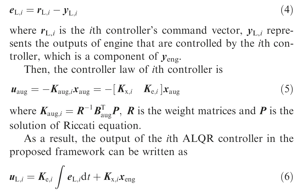
Moreover, for a twin-variable controller, Liis designed to control the controlled variable yL,i= [yeng,0,yeng,i]Twhile yeng=[yeng,0,yeng,1,...,yeng,N]T,where yeng,0is a key parameter controlled in the main and all the limit protection loops.Also,its command vector can be written as rL,i= [reng,0,reng,i]T,where reng,0is the command for yeng,0and reng,iis the command for yeng,i. For model-based limit protection control, yeng,0is always selected as thrust, and yeng,ican be set as different limited parameters,and it leads to a benefit that the limited parameters are controlled directly when excesses of limits happen,which can ensure the limited parameter is kept at the limit line.
For clarify,note that yengis a output vector that consists of N+1 engine parameters yeng,i(i=0,1,...,N)that are scalars,while yL,iis a vector containing two engine parameters (i.e.yeng,0and yeng,i) from the vector yeng. Additionally, for the main controller L0’s controlled variable yL,0, one of its controlled variables is yeng,0and the other is an engine parameter no matter it has been listed in yengor not,which is determined by actual control demands. In this paper, for simplicity, the engine parameter yeng,iis selected without loss of generality,which means the main controller L0’s controlled variables are as same as the ith controller Li’s. But note that these two controllers are for different functions.
For simplicity, denote all the controllers as

Note that every control loop contains an individual controller, thus the control loop index is also represented by the corresponding controller index, namely Li.
Note that only one controller is used as the online controller when an online control loop is selected while other controllers are considered as offline controllers, and control signals generated by the online controller are fed into the engine. In terms of engine control, it is not allowed to change inputs of the engine abruptly, which may cause dangerous impacts on the engine operations even an accident. However,several controllers are designed for different control purposes in the proposed framework, and the switch among these control loops is expected to occur when different control conditions are satisfied. It means that outputs of the control loops should be the same to avoid the discontinuity of inputs of the engine when the switch of control loop occurs.
Thus, a simple strategy, which re-initializes the offline controller, is implemented. Concretely, for the ith offline controller, the controller’s error integrator is initialized to zero,and the reference of rL,i,yL,i,xengand uL,iare reset to the current engine operating point and the online control signals. It means that the same control signals are constructed by different controllers every sampling period. Therefore, the continuity of control signals that are fed into the engine is satisfied completely. When this control loop is activated as the online control loop,the reset operation for this control loop is paused and the controller’s behavior is decided by the error signals generated by subtracting the feedback of engine outputs from the command given by the command reconstruction module.
4. Control loop selection and switch logic
Min-Max logic is a control loop selection logic essentially,and its selection structure makes itself unsuitable to be applied in the framework of multivariable control anymore because it is difficult to compare output vectors of multivariable controllers and determine which one is maximum or minimum. Consequently,single-variable control is used in Min-Max logic while other controllable variables are given in the open-loop features.Therefore,a new control loop selection and switch logic is proposed, which aims at selecting and activating the appropriate control loop during the engine operation.
This logic consists of a prediction module,a judgment module for limits, and a control loop switch logic. Engine parameters over next few sampling periods are predicted by the prediction module, and these predictions of parameters are compared with boundaries of limited parameters in judgment module to determine whether one or more parameters tend to go beyond limits in next few sampling periods. Finally, the switch logic activates an appropriate control loop.
4.1. Prediction module
Parameter predictions have two main functions in the proposed framework. Firstly, they are conducted to monitor the trend of excess of limits, which further helps the control loop selection logic to activate the corresponding control loop.What’s more, predictions provide a series of available operating points that can be used to reconstruct new commands when an excess of limits of parameters happens, which is detailed in Section 5. Thus, a novel closed-loop prediction method, which provides predictions by simulating the whole system, is presented in the proposed framework to conduct accurate predictions. It means the engine operation is predicted with a specific control loop, which benefits the control loop selection.
Concretely, the predictive model is a discrete state-space model linearized from the onboard model.

It is worthwhile to mention that the state-space model is built at time instant k- 1.m denotes the discrete-time instant of a discrete-time state-space model while k denotes the simulation time instant,so the prediction vector yeng,k+m,pof future time instant k + m equals to yeng,mof Eq. (8) by conducting prediction with Eq. (8) at time instant k, where subscript ‘‘p”denotes predicted parameters.
In this paper, the linearization method presented in Refs.45,46is implemented to construct the state-space model shown in Eq.(8),in which a component level model that has the capability to calculate thermodynamics parameters and their derivatives simultaneously is selected as the onboard model.For every simulation instant k-1,the control signals are sent into this onboard model, then the baseline values of Eq. (8),namely xeng,k,xeng,k-1,ueng,k-1,yeng,k-1,are given by the thermodynamics calculation while derivatives, namely Aeng,k-1,Beng,k-1,Ceng,k-1and Deng,k-1,are given by the partial derivative calculation.
Then, the closed-loop control system can be simulated by considering a specific control loop with controller’s states of time instant k - 1 and the state-space model built at time instant k - 1, which means that the whole system dynamics under the specific control loop can be taken into account. In other words, it evaluates the possibility of an excess of limits of limited parameters under either the case that the online control loop is maintained or the case that the control loop switch happens.
Assume that the prediction horizon is npand ith control loop, Li, is considered. After that, the prediction process with the control loop Liat time instant k can be summarized as follow.
Step 1. Initialize m = 0.
Step 2. Construct the command rL,i,k+0for prediction.
Step 3. Feed engine’s output vector yL,i,k-1of time instant k-1 and the command rL,i,k+0into the ith control loop to calculate control signal vector uL,i,k+0.
Step 4. Predict parameters for time instant k + 0, namely yeng,k+0,pby Eq. (8).
Step 5. m = m + 1.
Step 6. Construct the command rL,i,k+mfor prediction.
Step 7. Feed prediction vector yL,i,k-1+m,pand the command rL,i,k+minto the ith control loop to calculate control signal vector uL,i,k+m.
Step 8. Predict parameters for time instant k + m, namely yeng,k+m,pby Eq. (8).
Step 9.If m=np-1,go to Step 10,else go back to Step 5.
Step 10. End.
Note that the vector yengis predicted every time the prediction process is conducted, but only some of its elements (i.e.yL,i) is feedback to the controller. It can be seen that the closed-loop system is simulated by using a state-space model instead of the online nonlinear model,which can achieve much less computational burden.Normally,npis set to a small number, so only a series of matrix calculation is required. In addition,more accurate predictions can be gotten than predictions attained by maintaining current inputs of engine in an openloop way, because future control signals for engine are predicted as an intermediate step.
4.2. Limitation judgement
In the proposed framework, there are several controllers designed for different limit constraints,however,only one control loop is delegated as the online control loop. Thus, it should be determined which control loop should be activated as the online control loop.
As mentioned above, the prediction module provides parameter change information that is used to judge the possible excess of limits in advance.Taking time instant k for example, the prediction series yeng,k,p, yeng,k+1,p,..., yeng,k+np-1,pare obtained with the response calculation of Eq. (8).
For simplicity, denote limits of limited parameters as

Note that for some limits, such as limits of surge margin,are the lower bounds of limited parameters while other limits of parameters are the upper bounds, and some of them may be triggered in acceleration while others may be triggered in deceleration. The upper-bound limit during the acceleration is discussed as an example in our paper while lower-bound limits can be judged in a similar way.
Again, take a twin-variable controller as an example, the limit protection loop Liis used to limit ith limited parameter yeng,i. If there is only a parameter, yeng,i, going beyond the limit, the related limit controller Libecomes the target controller and the corresponding control loop becomes the target control loop.Then,it becomes the online control loop after the real control action happens. However, criteria have to be designed to determine which limit protection control loop should be activated as the target control loop if there is more than one parameter exceeding their limits.Due to the fact that different physical signals cannot be compared directly, a comparison based on static gain conversion is developed.
Concretely, as the fact that there is a multivariable model and generally inputs (namely control signals) are changed together in a multivariable control loop, so all the inputs are perturbated one percent together and these inputs are fed into the predictive model shown in Eq. (8) to calculate predictions over two sampling periods, i.e. np= 2 (namely the value of yeng,k+mis calculated where m=1).The reason is that parameters change cannot be reflected by Eq.(8)because of the delay characteristic of a discrete state-space model if npis set to 1.Also, if npis too large, the current operating point may not be reflected by calculated static gains because the predicted operating point is a little far away from the current operating point. Then, the static gain of an element of yeng,k+1can be defined as the ratio of the change of the parameter Δyeng,i,k+1to the perturbation size of an input.

where Δu1denotes the perturbation size of the first element of input vector ueng.
Note that the denominator can be any element of uengas long as the same element is used to calculate the static gains,and these gains are re-calculated based on the latest predictive model every sampling period.
Thus, these static gains are denoted as the set K, namely

For ith parameter exceeding its limit,the amplitude beyond the limit of yeng,ican be calculated.
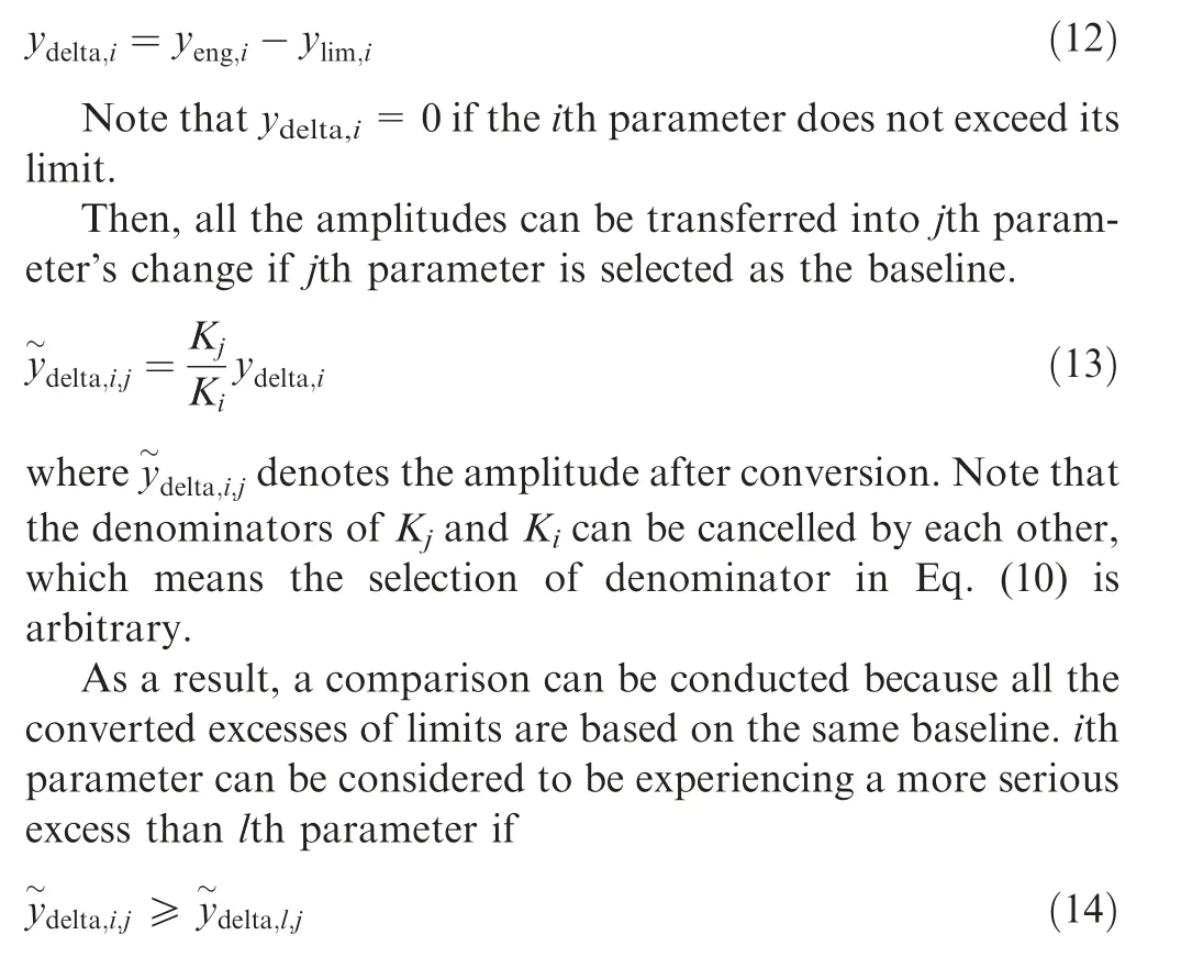
As a result, the limit protection loop Liis delegated as the target control loop, which means that the control loop containing Liwill be the online control loop after the real control action occurs. It can be seen that if there is more than one parameter going beyond limits,a limit protection loop is going to be activated. For a special case where there are same converted amplitudes beyond limits, a priority of all the limited parameters can be defined to ensure that a specific parameter can be limited first,which means that a preferred limit protection loop can be activated in this special case. Moreover, if other limited parameters continue to exceed their limits when a limit protection loop is activated,a control loop switch could be made to restrict another limited parameter that is predicted to exceed its limit most seriously in the future sampling periods.
Therefore,the judgment process can be summarized as follow. Without loss of generality, assume that the priorities of limited parameters are given as that smaller i has a higher priority.
Step 1. Initialize m = 0.
Step 2. Check whether there are elements of yeng,k+m,pexceeding limits. If yes, go to Step 4, otherwise, go to Step 3.
Step 3.m=m+1.If m ≤np-1,go back to Step 2,otherwise go to Step 5.
Step 4. If only a parameter is predicted to go beyond the limit, then the related control loop becomes the target control loop. If more than a parameter is predicted to exceed limits,then the target control loop is determined according to Eq.(14).
Step 5. End.
4.3. Control loop switch
Based on the prediction module and the judgment module,the logic for control loop selection and switch can be well developed. The behaviors of control loop selection and switch can be divided into two types, and one is to trigger a limit protection loop and the other one is to activate the main control loop. Thus, a mechanism should be defined to determine whether the control system should activate a limit protection loop and how to exit it. Due to the particularity of the limit protection control,the engine should be controlled by the main control loop for most flight conditions to realize the main control objective when it is possible. Thus, assessing the engine operation with the main control loop should be the first task for the selection logic, and then the engine operation with a limit protection loop is predicted if it is necessary.
A control loop selection logic is developed and implemented in the proposed framework according to the above analysis. Assume that the ith control loop, i∈{0,1,...,N}, is the online control loop at time instant k - 1. Then, the logic for time instant k can be summarized as follow.
Step 1. Conduct the prediction process with the main control loop L0.
Step 2.Use the judgment module to check whether there is any prediction going beyond the limit. If yes, go to Step 3,otherwise set L0as the target control loop, and then go to Step 5.
Step 3.Conduct the prediction process with the online control loop of last time instant, i.e. Li.
Step 4.Use the judgment module to check whether there is another parameter of which predictions going beyond the limit most seriously. If yes, set the related limit protection loop as the target control loop, otherwise set Lias the target control loop.
Step 5. Use the target control loop as the online control loop to control the engine.
Step 6. k = k + 1.
Step 7. If the simulation ends, go to Step 8, otherwise, go back to Step 1.
Step 8. End.
Above control loop selection and switch logic can be regarded as an extension of traditional Min-Max logic. Traditional Min-Max logic selects control signals by minimum and maximum operations, which is an implicit control loop switch among different control loops. Furthermore, the minimum and maximum operations determine that the engine is controlled by the limit protection loop related to the limited parameter that is regarded as being exceeding its limit most seriously based on its selection logic. For the proposed method, the switch among control loops is also a necessary step to achieve limit protection control, and the selection is based on a novel evaluation that determines which one is the most serious case. Secondly, engine parameters of last time instant are fed back into different single-variable controllers in Min-Max logic, which indicates that the limit judgment is based on current engine outputs. For the proposed method,the prediction is implemented, of which advantage is that changes of parameters are used to activate a limit protection loop in advance, but the prediction horizon that is not too large ensures that the activation of the limit protection loop will not happen too early. According to Eq. (8), if the control signals of time instant k - 1 is used for prediction, the proposed method judges the possible limit excess based on the latest engine state as the Min-Max logic does.
5. Command reconstruction
Different commands are required for different control loops,therefore how to construct required commands is an important issue for the framework. Furthermore, a proper command combination is of importance for limited protection control.For example, assume that ith controller’s command vector is two-dimensional,namely rL,i=[reng,0,reng,i]T.It is obvious that if the elements of the command vector for Licannot match each other properly, the operating point that this command vector defines cannot be reached by the engine, even a control accident may be caused. Indeed, when a limit excess happens,it is not suitable to combine the given command rrefg,0with the limit value as the command vector rL,i.Instead,reng,0should be reconstructed to ensure that it matches the limit command reng,i. Thus, the command reconstruction method is designed according to different combination modes of control loops.
The combination of possible control loops of last time instant and of the current time instant can be classified into five modes as shown in Table 1,where i∈{1,2,...,N}, j∈{1,2,...,N}and i ≠j.The initial control loop denotes the control loop that is the online loop of last time instant, and the target control loop denotes the control loop that is to be activated at the current time instant.
It can be seen that Mode 1, Mode 3 and Mode 4 represent cases that limit protection control is activated, while Mode 2 and Mode 5 denote cases that limit protection control is deactivated. Also, Mode 1, Mode 2 and Mode 4 are the case that the control loop switch happens while Mode 3 and Mode 5 means that the control loop of last time instant is maintained.
Concretely, Mode 1 represents that the main control loop L0is going to be transferred to Liwhen ith limited parameter yeng,itends to go beyond its limit while L0is the online controlloop. Mode 3 denotes the case that Licontinues to be the online control loop. This case must happen after Mode 1 or Mode 4 occurs, and continuous commands are required to ensure the engine operates back within safe boundaries. In contrast,Mode 4 means that jth limited parameter is predicted to be the only one exceeding the limit or exceeding its limit most seriously while ith limit protection loop has been activated as the online control loop.This means that another limit protection loop is going to be triggered during the process of controlling the ith parameter.

Table 1 Possible control loops of last time instant and of current time instant.
Mode 2 denotes the case where limit protection control is deactivated and the control signals are given by the main control loop, and it is the approach to quit the limit protection control in the proposed framework. Mode 5 indicates that no excess of limits is going to happen and the engine continues to be controlled by the main control loop L0,which is expected to occur during the operation of the engine and to achieve main control objectives.
Thus,different command reconstruction approaches can be designed for different modes, and boundaries that tend to be triggered during acceleration are taken as an example to describe how to conduct it.
For Mode 1 and Mode 4, a limit protection control loop that is different from the online control loop is going to be activated regardless of which control loop is the online one. It means that commands of the initial control loop cannot be changed simply to commands requested by the target control loop because there are different controlled limited parameters although the main controlled variable yeng,0is the same.Therefore, the command reconstruction can be designed as follow.Assume that ith limited parameter is predicted to exceed its limit at time instant k+q,and note that the prediction is calculated at time instant k. If q > 0, it is predicted that the ith limited parameter does not exceed its limit at time instant k + q - 1 but goes beyond its limit at time instant k + q.Then, the command for Liat time instant k can be reconstructed as

where Tsis the time constant of the first-order filter that should be fine-tuned, Tris the count of periods and starts from 1, Tcis the time constant that can be fine-tuned and it is 0.04ln 10 in paper.
If q=0 and the converted excess of the limited parameter,i.e.delta,i,j,k,is obtained after limit judgment,which means that the ith limited parameter tends to exceed its limit immediately at time instant k. Then, the command for Liat time instant k can be reconstructed as

For Mode 3,the online control loop is unchanged actually,which means that no control loop switch is required. Therefore,for the same control loop,the continuity of the command is considered, and a command recursion process is developed as follows.

It can be seen that the second item on the right sides of above equations will dominate the command as the time increases. Besides that, it can be found that the value of the main controlled variable, namely yeng,0,k-1is fed back to construct the command in Eqs. (15) and (16) while the command of last time instant reng,0,k-1is implemented to reconstruct new commands in Eq. (17) because Eqs. (15) and(16) is used for a control loop switch process while Eq. (17) is a kind of command recursion.
The main control loop is going to be the online control loop in Mode 2 and Mode 5 although these two modes represent two different cases.A control loop switch must occur in Mode 2 but the online control loop, i.e. the main control loop, L0,remains in Mode 5.However,these two modes are completely different from Mode 1,Mode 3 and Mode 4 because the target control loop is the main control loop, which means that the given command will not lead to an excess of limits during the engine operation controlled by the main control loop. As a result,the given command can be used to achieve real control objectives. Thus, the command for L0at time instant k for Mode 2 can be given as follow.
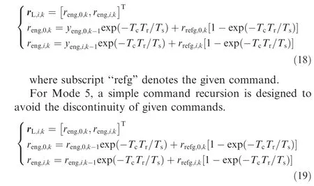
Note that for Eqs. (18) and (19), given commands rather than predictions are implemented to reconstruct new commands in the second item of the right side of equations, and Eq. (18) that uses the feedback from engine is designed for the case when a control loop switch happens while Eq. (19)that uses the commands of last instant is used for command recursion when the main control loop is still the online loop.
It can be seen that the prediction of main controlled variable,namely yeng,0,p,is used to reconstruct the main command in Eqs. (15)-(17). As mentioned above, the given command may not be suitable when a limited parameter exceeds its limit and the related limit protection loop tends to be activated. In contrast, predictions that denote a series of operating points,which may be more reasonable than the operating points defined by given commands, can be recognized as a series of feasible operating points because they are predicted to be reached during the engine operation. Thus, it is reasonable to use these predictions to reconstruct real commands that are sent to the online control loop. It can be considered that the prediction vector yeng,k+q-1,pdefines an operating point that is close to ith limited parameter’s boundary, so it is suitable to combine its element yeng,0,k+q-1,pwith the limit value of ith limited parameter as the command of ith control loop in Eq. (15). Instead, the prediction used in Eqs. (16) and (17)defines an operating point where the engine can reach at the cost of that limitations for limited parameters are violated.Thus,the amplitude beyond the limit of the ith limited parameter is converted to an equivalent amplitude of the main controlled variable, and then the prediction is modified according to this amplitude. It should be mentioned that the adaptive feature in command reconstruction is reflected because this modification is completed adaptively according to parameter static gain shown in Eq. (11) and the predicted amplitude beyond the limit.
Besides that,a control loop is selected according to the current engine operating state and its predictions, and the command reconstruction and control loop selection is interdependent.It means that when a control loop is delegated,the corresponding command reconstruction is also decided because the command reconstruction depends on the determined combination mode control loops.
In terms of tracking commands, these predictions are obtained by using given commands. Concretely, commands for predictions are constructed in a simple recursion process that is similar to Eqs.(18)and(19)but with relative parameter commands, namely no modifications are made for these given commands, and the closed-loop prediction is implemented in this framework, so the change of given commands can be reflected by these predictions, which suggests that changes of given commands can make an influence on reconstructed commands for control. In other words, reconstructed commands can track given commands if given commands are feasible.
6. Test case
6.1. Simulation setting
In order to validate the effectiveness of the proposed multivariable framework for limit protection control, this method is implemented in a low bypass twin-spool mixing-exhaust turbofan engine,which consists of inlet,fan driven by Low-Pressure Turbine (LPT), compressor driven by High-Pressure Turbine(HPT), combustion, mixing chamber and nozzle, as an example. For this simulated engine, main fuel flow and nozzle area are selected as controllable variables to achieve the control of engine operation by different control loops.
A well-developed high-fidelity component level model that consists of a basic thermodynamics model and a partial derivative model for the simulated engine is used as the onboard model, and the modelling details can be found in Refs.45-48.Four co-operating equations, including the continuity of mass flow at the high-pressure turbine inlet, the continuity of mass flow at the low-pressure turbine inlet, the pressure balance at the mixing chamber and the pressure balance at the throat of the nozzle,and two equations for the rotational speed calculation of low-pressure shaft and high-pressure shaft based on shaft dynamics,are used to simulate the engine transient operation,and every component’s performance parameter is calculated according to component maps during iterations. For given inputs, including altitude H, Mach number Ma, main fuel flow mfband nozzle area A8,four co-operating equations are solved by the Newton-Raphson method and shaft speeds are updated after solving the co-operating equations every sampling period.
Four engine parameters, including thrust F, low-pressure shaft speed nf, surge margin of fan component SMfanand TIT are considered.As a result,four twin-variable ALQR controllers are designed for the proposed framework,and thrust F is the major controlled variable, namely yeng,0, of which command is given by thrust control schedule according to flight condition and Power Level Angle (PLA). Concretely, a main controller is designed to control parameters thrust F and surge margin SMfan, while three limiters are designed to control the combination of F and nf, the combination of F and TIT and the combination of F and SMfanrespectively. It means that maximums of the low-pressure shaft speed and TIT and minimum of SMfanare considered as limits in the paper. It can be seen that thrust is controlled all the time regardless of which control loop is the online one,and it is controlled together with another parameter. Note that all the parameters expect SMfanare normalized relative to the design point.
Besides that,there are two parameters that should be set in the proposed method, namely prediction horizon npand time constant Ts.As described above,Tsis an important parameter in the proposed method because it is used to generate new commands. Different changeable commands are constructed with different Ts, and it further influences the response time of engine parameters, which suggests that Tsshould be finetuned. The selection of prediction horizon npusually is set empirically in prediction-based applications,5,21and a larger prediction horizon is preferred when the prediction accuracy is acceptable. As partial derivative-based state-space model shows an acceptable accuracy for predictions of future time instant k + 5,46npis set to 6 after trial and errors, which means that parameters from time instant k + 0 to k + 5 are predicted every prediction process.
As the above analysis,the proposed method can be considered as an extension of traditional Min-Max logic, so Min-Max logic is implemented as a comparison. For this logic,three single-variable LQR controllers with the same controller-reset strategy is designed for using main fuel flow mfbto control thrust F, low-pressure shaft speed nfand TIT respectively while nozzle area is given in open loop, and the controller feedback gains are well fine-tuned, then the schematic can be shown as Fig. 3 because only upper limits are considered as an example in our paper. Note that the controller for SMfanis not designed because it is not suitable to use main fuel flow to control SMfanin a way of singlevariable control, which also indicates one of the benefits of the proposed framework that controlling SMfanis achievable in a way of closed-loop control and also suggests the advantage of multivariable control.
In addition, the sampling period of control is set to 20 ms,and limits for nf,TIT and SMfanare 1.02,1.06 and 5%respectively, i.e. nf≤1.02, TIT ≤1.06, SMfan≥5%.
6.2. Results and discussion
6.2.1. Selection of time constant
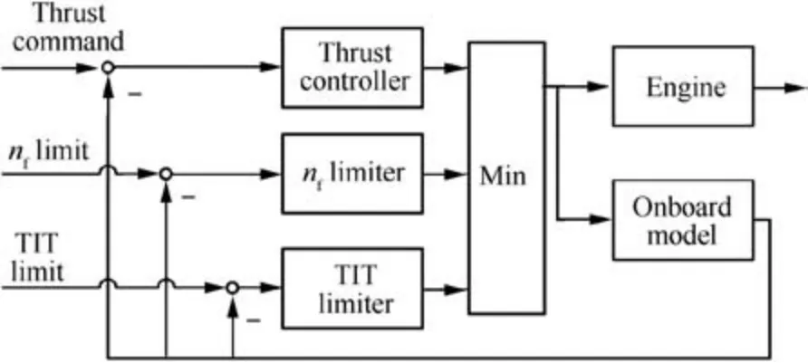
Fig. 3 Min-Max control considered in paper.
It can be seen that time constant Tsis a key parameter to reconstruct new commands according to Eq. (15) to Eq. (19).Different selections of Tsmeans different trajectories of commands. The too large time constant Tsshould not be chosen because it can make reconstructed commands track commands given by the control schedule too slow, which further influences the response time of parameter relative to man-made command (i.e. control schedule). For the simulated case, in terms of model-based control, the response time of thrust should be paid attention to.On the other hand,the much smaller time constant represents a shorter and sharper transition of commands, and it is easy for an abrupt change of commands to cause a large overshoot because it is difficult for ALQR controllers to maintain monotonicity when they are implemented to a nonlinear model. Thus, three different time constants,namely 0.2 s,1.0 s and 2.0 s(i.e.10,50,and 100 sampling periods), are studied, and the simulation is conducted at altitude 8 km and Mach number 0.9 with prediction horizon np= 6 as an example.
Fig. 4 shows the responses of four parameters during the acceleration and deceleration with three different time constant Tssettings. Especially, the command in Fig. 4(a) refers to the thrust command given by the corresponding control schedule.
Fig.4 shows that different responses are caused by different time constant settings.Concretely,the limit protection control is activated with all the time constant settings and maximum shaft speed limited to 1.02 for all the cases, but a little larger thrust is reached when a larger time constant (Ts= 2.0 s) is implemented. It suggests that different engine operation can be influenced by different time constants, and slower response but smaller overshoot are caused when a larger time constant is implemented, which suggests that constructing a smoother command can make the engine reach the limitation line smoother. However, a larger delay is experienced by thrust response with a larger time constant by comparing thrust responses with given commands. Thus, Tsis set to 0.2 s for the simulation in wide flight envelope as much faster thrust responses can be achieved while steady-state thrust loss closes to those with other time constants.
Besides that, this simulation indicates the necessity of reconstructing the command because it can be seen that there is a considerable gap between the given command and the real thrust engine achieve.As a result,if the thrust command is not modified, a mismatching of thrust command and limitation command can be caused, which can make a negative impact on multivariable-controller behaviors.
6.2.2. Simulation in flight envelop
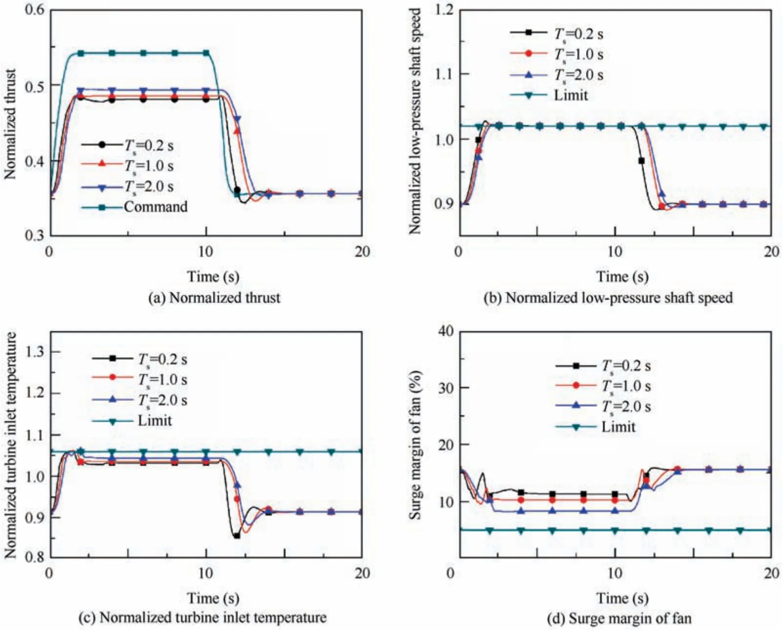
Fig. 4 Parameter responses with different time constants.
The simulation is conducted in a wide flight envelope as shown in Fig. 5. As mentioned above, achieving direct thrust control is the most critical feature of model-based control,and the aim of the proposed method is to ensure that thrust tracks the command as much as possible by making full use of advantages of multivariable control. Therefore, Eq. (20) is implemented to assess the loss of thrust caused by limit protection control.

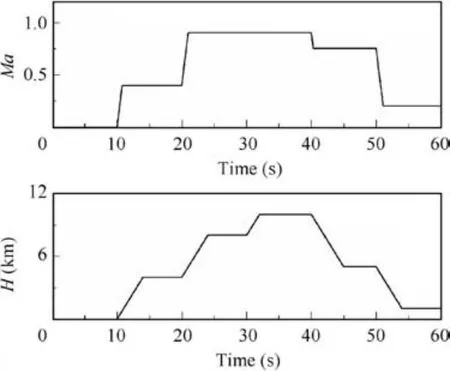
Fig. 5 Flight condition change in flight envelope.
Fig. 6 shows the responses of controlled variables with different limit protection control logic.Legend‘‘Main controller”means that there is no limit protection control applied and the engine is only controlled by the main control loop. ‘‘Min-Max” denotes the responses with Min-Max logic while‘‘MLPC”denotes responses under the control of the proposed method. Fig. 7 shows the control loop switch during the simulation, where control index ‘‘0” denotes the main control loop,‘‘1”is the limit protection loop for nfand‘‘2”is the limit protection loop for TIT and‘‘3”is the limit protection loop for SMfan. Note that for Min-Max logic the limiter is the singlevariable controller while it is the twin-variable controller for the proposed method. It is also worthwhile to mention that predictions are conducted before control action occurs at the current time instant.
Figs. 6 and 7 show a complicated and large transient operation of engine with changed altitude and Mach number in a wide flight envelope, and the engine is going to break the limitations to track the thrust command under the control of the main control loop when there is no limit protection control implemented.Concretely,transient violation is caused at some time instant such as the beginning of 20 s, while steady-state violation is caused during the period from 20 s to 30 s and 40 s to 50 s, during which the steady-state low-pressure shaft speed are 1.050 and 1.053 respectively when no limit protection control is implemented, and also the steady-state TIT goes beyond its limit with 1.080 and 1.089. Thus, while the engine is controlled by the main control loop for the most time, the limit protection control is activated at different simulation time instants because of transient violation and steady-state violation of limitations, and all the limited parameters are pulled back within their boundaries. Also, the control loop switch happens frequently when the flight conditions change,such as the beginning of 20 s; in contrast, a specific control loop is kept during the steady-state running, which indicates that it is easy for a large transient operation to trigger different limits.
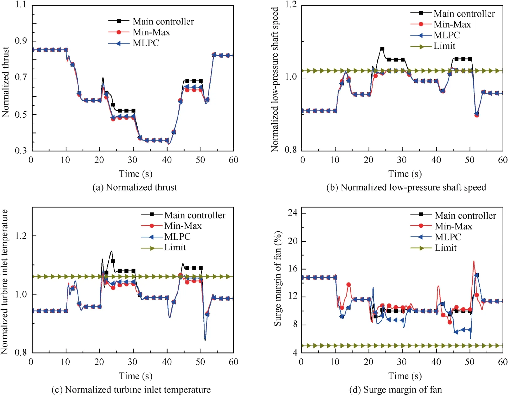
Fig. 6 Parameter responses with different limit protection control.
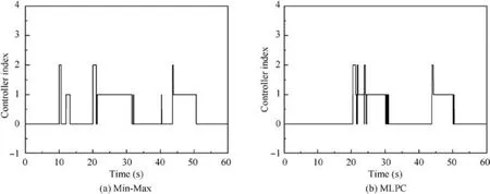
Fig. 7 Online controller index during simulation.
Fig. 8 shows the reconstructed command used in the proposed framework during the simulation. Fig. 8(a) compares the reconstructed command of thrust and the given thrust command, and Fig. 8(b)-(d) show the commands of surge margin of fan, of low-pressure shaft speed and of TIT.
Fig.8(a)shows that the thrust command is continuous during the simulation, because the thrust is the main controlled variable controlled by all the controllers. When a limit protection loop is activated,the given thrust command cannot match the command of the limited parameter, so the given thrust command is modified automatically to match the corresponding commands of the limited parameter,which shows the capability to reconstructing thrust command adaptively. In contrast, the reconstructed thrust command tracks the given commands well when the main control loop is the online one.
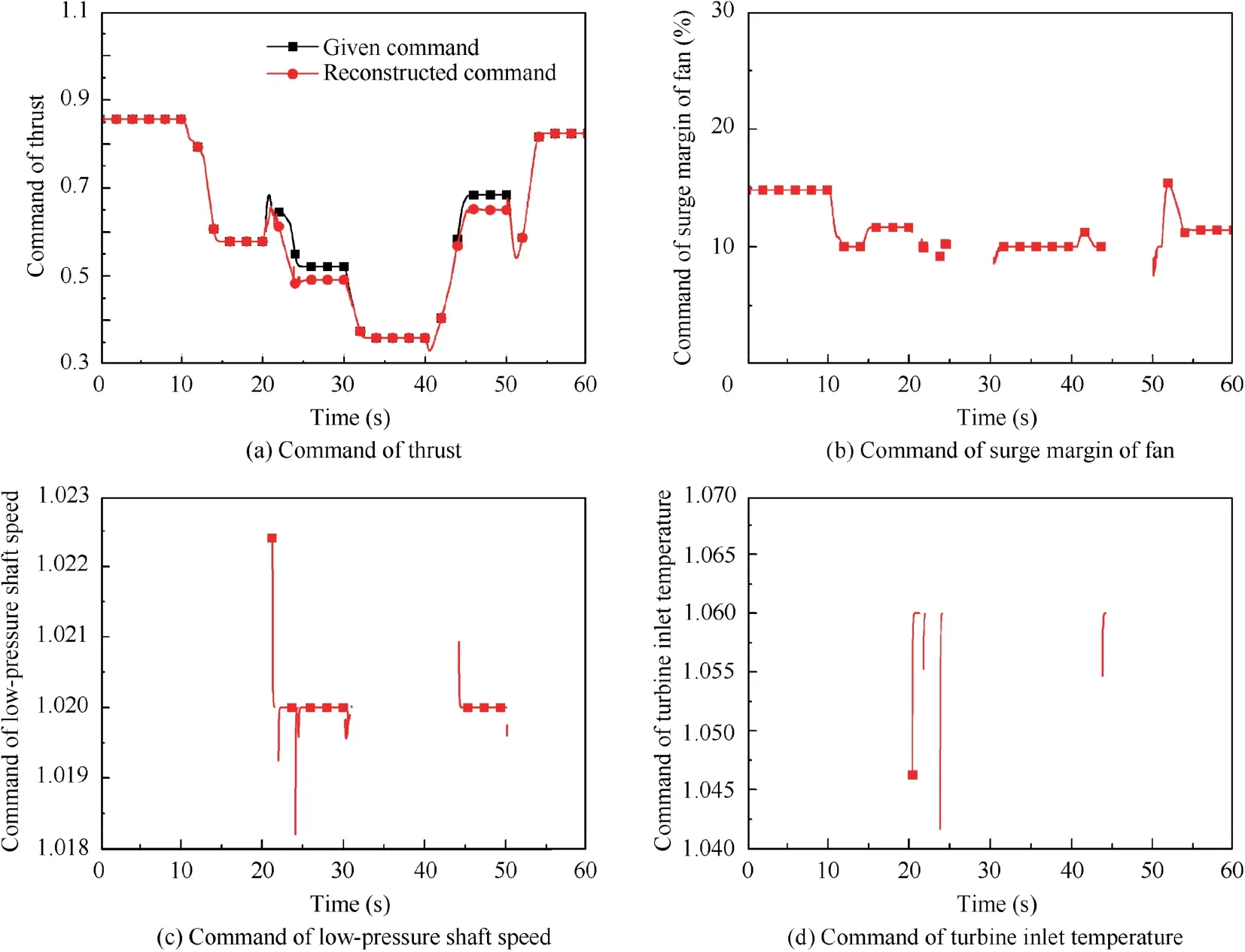
Fig. 8 Reconstructed commands.
For other three parameters,commands are not continuous,because the second controlled variables depend on the online control loop. Thus, as shown in Fig. 1, there is no command for the parameter when the corresponding control loop is offline; instead the controller-reset strategy is switched on. Note that Fig. 8(b) shows the command of surge margin when the main control loop is online because the limit of surge margin of fan is not violated and the limit protection loop for surge margin is not activated. However, Fig. 8(c) and (d) denote commands for limiting low-pressure shaft speed and TIT. It can be seen that the change of reconstructed commands for these two limited parameters are towards their limit lines,which aims at driving the engine to operate in the limit lines.Also, there are two command lines starting from the point above the limit value of low-pressure shaft speed (1.02), it is because the start point of command reconstruction, such as the first item on the right side of Eq.(16),begins from the real engine operating point. For instance, at simulation time instant 21.24 s, the limit protection loop for TIT is online.The low-pressure shaft speed is 1.0238, which is a little larger than its limit value and it is predicted to exceed the limit most seriously at predicted time instant k+0 based on comparison of converted amplitude at time instant 21.26 s. Thus, Eq. (16)is implemented to reconstruct the thrust command and the limit command for low-pressure shaft speed, and the value 1.0238 is used as the start point. With the simulation continuing,the limit command for low-pressure shaft speed changes to its limit value (1.02) gradually.
Table 2 gives information about the loss of steady-state thrust because of triggering the limit protection control.
It can be seen from Table 2 and Fig.6 that the largest losses of thrust are caused by Min-Max logic, which are 5.57% and 7.12% respectively. In contrast, all the losses of thrust caused by the proposed method are smaller than those caused by Min-Max logic,and improvements are 25.49%and 30.06%respectively, which highly indicates that the proposed limit protection control method, in which multivariable control techniques are implemented, can improve the loss of thrust effectively by comparing with Min-Max logic that cannot make full use of the potential of multiple controllable variables. It can also be demonstrated from Fig. 6(b)-(d) that the engine reaches a higher TIT under the control of the proposed method than that under Min-Max logic’s control,which is realized by lowering surge margin.However,the larger surge margin is caused by Min-Max logic by comparing with that without limit protection control because the nozzle area is given in an open-loop way, by which some possible adjustments of engine operation are dismissed.
In addition,it can be seen from Fig.7 that there is an obvious difference in the control loop switch between Min-Max logic and the proposed framework. For example, for Min-Max logic, the control signal, i.e. main fuel flow, of the limit protection loop for TIT is selected at 20.02 s, which is much earlier than a limit protection loop is activated for the proposed method, and the latter are 20.42 s. Besides that, limit protection loops are activated during 10 s to about 15 s and the beginning of 40 s under Min-Max logic’s control while the main control loop holds for these periods with the proposed method, and no excess of limited parameters is caused during these two periods in Fig. 6(b) and (c), which suggests that a reasonable activation of control loop can be given by proposed logic.
Fig.9 shows how many parameters are predicted to exceed their limits during the simulation by the prediction procedure with the main control loop and with the online control loop of time instant k - 1.
Fig. 9 shows that the predicted numbers of parameters beyond limits are different between prediction with the main control loop and with an online control loop. It can be seenthat it is easier for limited parameters to be predicted to go beyond limits under the main controller’s(control loop’s)control because unmodified commands are fed into the main controller. In contrast, some limited parameters are not predicted to exceed limits under the online control loop.For example,at simulation time 22.38 s, the limit protection loop for nf, L1, is online. Then, predictions with main control loop are conducted first at 22.4 s, and there is a parameter being predicted to exceed the limit, which means that the control loop switch from the online control loop to the main control loop is not allowed. After that, predictions with the online control loop is conducted by using recursive commands, and no limitation violation is predicted. It is easy to be understood that the recursive commands are specifically designed for imposing restrictions on the limited parameter,thus parameters are predicted to stay within safe boundaries under the online control loop while they are predicted to break the limitations if the limit protection control is not implemented.

Table 2 Thrust loss under different limit protection control.
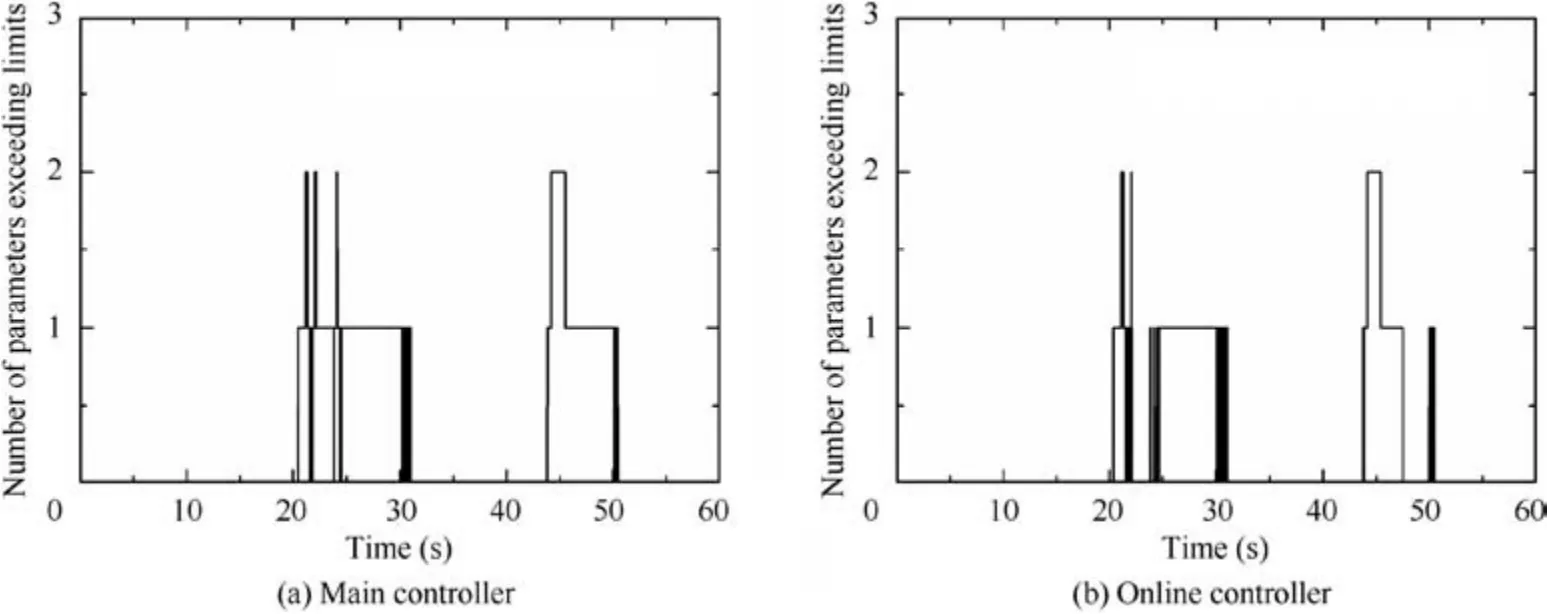
Fig. 9 Number of limited parameters being predicted to exceed limits.
It is also worthwhile to mention that a proper limit protection loop is chosen although there is more than one parameter being predicted to exceed their limits. For instance, two parameters,namely nfand TIT are predicted to go beyond limits at simulation time 45 s,but the limit protection loop for nfis selected by comparing their converted amplitudes beyond limits, which demonstrates the effectiveness of the proposed method for solving the case that there is more than one parameter beyond limits.
7. Conclusions
(1) A novel limit protection control framework for multivariable control is proposed, which can be considered as an extension of the single-variable Min-Max controller to some extent as switching among multiple controllers, which is the essence of Min-Max logic, is followed in the proposed method. The benefit of using multiple controllers is that the corresponding limit line can be reached when controllers are well designed and relative commands are reasonable.
(2) A command reconstruction method is designed for solving the problem of command mismatching, which does not exist in single-variable based Min-Max logic. This method can adjust the command adaptively according to static gains of parameters at every operating point,and static gains are provided by a continuously updated state-space model by online linearization. The control loop selection and switch logic,which is based on prediction and static gain-based conversion of amplitude beyond limits, is also proposed to determine which control loop should be delegated as the online control loop.
(3) A parameter,namely time constant,is introduced to the command reconstruction process, which influences the response of controlled variables. The simulation results show that a larger time constant can make the response smoother and cause relatively smaller thrust loss due to triggering limit protection control, while a smaller one can ensure a greater response speed.
(4) A nonlinear simulation is conducted in the wide flight envelope,and the results show that limit protection control can be well activated and safe operation can be guaranteed, which demonstrates the effectiveness of the proposed method. Furthermore, by comparing with classical Min-Max logic, the loss of thrust caused by limit protection control can be reduced significantly. In two flight conditions where the limit is reached, the loss of thrust is only 4.15%and 4.98%,which reaches up to 30% improvements by comparing with Min-Max logic.Thus, the advantage of the proposed method benefits from the multivariable controller is demonstrated.
(5) The proposed limit protection method can be implemented easily because it still belongs to traditional control architecture and no complex algorithms, such as nonlinear programming algorithms, are required. As a result, it does not require a huge computation burden in comparison with optimization-based control. For future work, it is interesting to investigate the performance of the proposed method by combining it with an onboard monitoring module that can be used to track engine degradations online such as extended Kalman filter.
Declaration of Competing Interest
The authors declare that they have no known competing financial interests or personal relationships that could have appeared to influence the work reported in this paper.
Acknowledgement
This study was supported by China Scholarship Council (No.201906830081).
 CHINESE JOURNAL OF AERONAUTICS2021年12期
- CHINESE JOURNAL OF AERONAUTICS的其它文章
- Entropy based inverse design of aircraft mission success space in system-of-systems confrontation
- Nonlinear resonance characteristics of a dual-rotor system with a local defect on the inner ring of the inter-shaft bearing
- Failure mechanisms of bolted flanges in aero-engine casings subjected to impact loading
- Synchronized perturbation elimination and DOA estimation via signal selection mechanism and parallel deep capsule networks in multipath environment
- Improving seeking precision by utilizing ghost imaging in a semi-active quadrant detection seeker
- A high dynamics algorithm based on steepest ascent method for GNSS receiver
