Investigation on surface integrity of electron beam melted Ti-6Al-4 V by precision grinding and electropolishing
Jiang GUO, Min Hao GOH, Pan WANG, Rui HUANG, Xiaohua LEE,Bin WANG, Sharon Mui Ling NAI, Jun WEI
a Key Laboratory for Precision and Non-traditional Machining Technology of Ministry of Education, Dalian University of Technology, Dalian 116024, China
b Ningbo Institute of Dalian University of Technology, Ningbo 315016, China
c Singapore Institute of Manufacturing Technology, Singapore 637662, Singapore
d Harbin Institute of Technology, Shenzhen 518055, China
KEYWORDS Additive Manufacturing(AM);Electron Beam Melting(EBM);Electropolishing;Grinding;Surface integrity;Ti-6Al-4V alloy
Abstract Electron beam melting (EBM), as an excellent Additive Manufacturing (AM) technology, enables the printing of Ti-6Al-4 V alloy for a wide range of applications such as aerospace and biomechanical industries. It improves functionality and integrity of components and negates complexities in assembly processes.However,due to the poor surface and sub-surface integrity represented by the rough surface finish and low dimensional accuracy, achieving a favorable surface condition is quite challenging.Therefore,post processing becomes essential for these electron beam melted (EBM-ed) Ti-6Al-4 V alloys. Being the most common technique to improve such parts,milling of Ti-6Al-4 V alloy is very challenging and resulting tool wear issues,due to its unique material properties.Thus,this paper presents a comprehensive study on the surface integrity of EBM-ed Ti-6Al-4 V parts processed by precision grinding and electropolishing, aiming to qualitatively and quantitatively clarify the interrelation between process parameters and processed surface quality.The surface and subsurface characteristics such as profile accuracy, surface roughness, microstructure,defective layer and residual stress before and after post processing were compared and evaluated. The results show that by precision grinding, the profile accuracy was improved from over 300 μm PV to 7 μm PV, while surface roughness (Ra) was reduced from 30 μm to about 2 μm.The layer with partially melt particles was removed, but introduced a deformed subsurface layer with more residual stress.Then by applying electropolishing,the residual stress was released and the deformed layer was removed. In addition, Ra was further reduced to 0.65 μm. The research can serve as a reference for the integration of post machining processes with AM.
1. Introduction
Ti-6Al-4 V alloy, also known as Ti64, is an Alpha-Beta (α+β) titanium alloy. It is recognized as the most popular titanium alloy for its superior material and mechanical properties.It has a wide range of applications, such as aerospace and biomechanical industries, where low density, high strength,excellent corrosion resistance and biocompatibility are necessary.1-3Conventional approach to manufacture Ti-6Al-4 V parts relies on forging, casting and rolling of bulk feedstock materials to form a rough shape. The fine features, dimensional accuracy and surface quality are thereafter achieved through subsequent processes, such as machining and polishing. However, these processes inevitably result in extensive material waste,high manufacturing cost and long lead time.4,5
Additive Manufacturing(AM),also known as 3D printing,is an emerging technology that has changed the way of manufacturing in recent years. Being a high-speed powder bed fusion AM technique, electron beam melting (EBM) not only enables the AM of Ti-6Al-4 V alloy,also improves functionality, integrity of components and negates extra effort from assembly processes to reduce lead time.6Complex Ti-6Al-4Vfeatures including porous cores, shell and even functional internal structures are enabled through EBM.6To date,research has been conducted on EBM-ed Ti-6Al-4 V alloy,mainly focusing on microstructure and mechanical properties.For instance, Wang et al. studied microstructure and microhardness through spatial and geometrical-based characterization, of an EBM-ed Ti-6Al-4 V component.7Brooks et al.did porosity detection in EBM-ed Ti-6Al-4 V using highresolution neutron imaging and grating-based interferometry.8Chastand et al. conducted a comparative study on fatigue properties of Ti-6Al-4 V specimens built by EBM and selective laser melting (SLM).9Besides, unlike the fully martensitic Ti-6Al-4 V printed by SLM that requires necessary post heattreatment, EBM produces excellent as-built mechanical properties. Studies have shown that standard heat treatments do not improve the properties significantly.10,11This makes EBM a competitive technology for applications requiring Ti-6Al-4 V with superior properties.
However, one non-negligible issue that disqualify an asbuilt EBM part from certain aeronautical or medical application is its low surface quality in terms of (1) low dimensional accuracy and(2)rough surface roughness.Our previous study7shows that the side surface parallel to the building direction has extremely rough surface quality (Fig. 1(b)). This is attributed to the irregular clustering of melted Ti-6Al-4 V resulted from the contouring process, more explanation is detailed in Section 2.1. As a result, post finishing process becomes essential for the EBM-ed Ti-6Al-4 V parts.Nonetheless,Ti-6Al-4 V alloy is known to be a difficult-to-cut material,especially when excellent surface is required. When machining Ti-6Al-4 V, a rapid increase in temperature at the tool-work interface leads to metallurgical alteration of the surface and subsurface layer and ultimately diminishes tool life through both nose and crater wear at elevated temperature.10,11At the same time, buildup edges(BUE)forms easily when the chips are welded on the tool’s rake face, which also affects the tool life drastically.Research has been conducted on the machining Ti-6Al-4 V alloy to improve surface quality for many years.For example,Sun et al. conducted a comprehensive experimental study on surface integrity by end milling Ti-6Al-4V.12Edkins et al.analyzed the surface and sub-surface microstructures by high speed machining of Ti-6Al-4 V alloy.13Setti et al. evaluated the performance of Ti-6Al-4 V grinding based on chip formation and coefficient of friction under the influence of nanofluids.14Yet the surface integrity of EMB-ed Ti-6Al-4 V is rarely investigated.15Although Beaucamp et al.did some preliminary study on the finishing of additively manufactured titanium alloy by shape adaptive grinding (SAG),16more research has to be conducted to scientifically and comprehensively understand this issue.
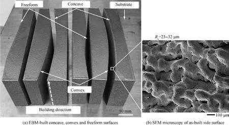
Fig. 1 Ti-6Al-4 V parts fabricated by EBM.
Apart from mechanical cutting,precision grinding is an efficient method for material processing of hard and brittle materials, has been successfully deployed in various industries.Owing to its deterministic material removal and surface finish,it is always used to fabricate high quality and functional parts with complex geometries.17In addition,tool wear is not a critical issue compared with cutting approaches. Nevertheless,electropolishing is an electro-chemical process that provides uniform material removal while relieving the machining stresses on the workpiece surface, which enables it to create a smooth and damage-free surface. Although Li et al. investigated the electro-chemical machining process, the fundamentals contribution of grinding and electropolishing was still not scientifically clarified.18
Hence, in this paper, a systematic surface integrity study was conducted aiming to achieve μm-level surface quality.The experiment comprised three approaches to finish the EBM-ed Ti-6Al-4 V freeform surfaces, namely (1) precision grinding, (2) electropolishing and (3) precision grinding followed by electropolishing.Through this study,optimal process parameters were identified by qualitatively and quantitatively investigating the interrelation between process parameters and surface quality. The necessary aspects including profile accuracy, surface roughness, microstructure, defective layer,and residual stress were incorporated in details. Based on the systematic analysis and evaluation,this paper serves as a comprehensive study on the surface integrity of EBM-ed Ti-6Al-4 V part polished using different approaches.
2. Experimental
2.1. Specimen preparation by EBM process
As shown in Fig.1(a),the EBM-ed Ti-6Al-4 V parts with concave, convex and freeform surfaces were fabricated by an Arcam A2X EBM system (software version 3.2, accelerating voltage 60,000 V, layer thickness 50 μm, Arcam AB standard build theme for Ti-6Al-4 V alloy). The pre-alloyed Ti-6Al-4 V powder supplied by Arcam AB had a nominal composition of Ti-6Al-4 V-0.03C-0.1Fe-0.15O-0.01 N-0.003H. The average powder particle diameter is 70 μm with a distribution range of 45-105 μm. A 210 mm×210 mm stainless steel start plate with a thickness of 10 mm was heated once the pressures of both the build chamber and electron beam column were below ~5×10⁻⁴and ~5×10⁻⁶mBar,respectively.The bottom temperature was measured by a thermocouple attached to the bottom of the start plate. When the bottom temperature reached 730°C,the parts were built directly onto the preheated start plate with a layer thickness of 50 μm by selective EBM.
The whole process was carried out under a vacuum of ~2×10⁻³mBar which was controlled by using high purity helium as a regulating gas to prevent powder charging. After finishing the build job and cooling to below 100°C, a powder recovery system was applied to remove the surrounding semisintered power from the built parts and to recycle the used powders. More detailed description can be found here.7Each layer of the EBM process is characterized by three primary process steps: preheating, contouring and melting. Each process step has a unique process parameter. In the preheating step,the entire powder bed surface is scanned at big focus offset and high beam velocity in order to maintain a high ambient temperature without sintering the powder,which can avoid the charging (charging of powder results in as widespread repulsion event referred to a ’smoking’). During the contouring step,only the layer perimeter is melted using relatively low currents and speeds in order to minimize surface roughness. The rough surface shown in Fig.1(b)is generated during this step,where powders near the contour path is partially melted and therefore sintered on the side wall, causing a coarse surface with large arithmetic roughness (Ra=23-32 μm). Lastly, the melting step was activated after contouring and the beam is scanned in a continuous raster pattern to melt the bulk portions.A rastering was conducted in a continuous snake pattern with 90° change in raster direction in the subsequent layer.
2.2. Precision grinding
Fig. 2 shows the experimental setup for the precision grinding process.The experiment was conducted by a precision grinding machine (SMART N10 KOMBI, ELB-Schliff Werkzeugmaschinen GmbH, Germany). It has a positioning resolution of 0.1 μm in all X-, Y-, and Z-axes. A Cubic Boron Nitride(CBN) wheel with a diameter of 300 mm and width of 8 mm was adopted to grind the as-built freeform surface. The feed depth, feed rate, and rotation speed of the wheel were listed in Table 1.
Parallel grinding, which is proved to achieve high form accuracy and good surface roughness, is adopted to do the freeform precision grinding. Here, y (x, z) is used to describe the profile of freeform surface.The machining path can be calculated according to the geometrical relationship between the workpiece and the grinding wheel. As shown in Fig.3,assuming the coordinate of grinding point G as (xg, yg, zg), its normal vector as n(a,b,c),and the coordinate of wheel center O as (x0, y0, z0), the machining path of grinding wheel can be therefore calculated as shown in Eqs. (1)-(3).19:
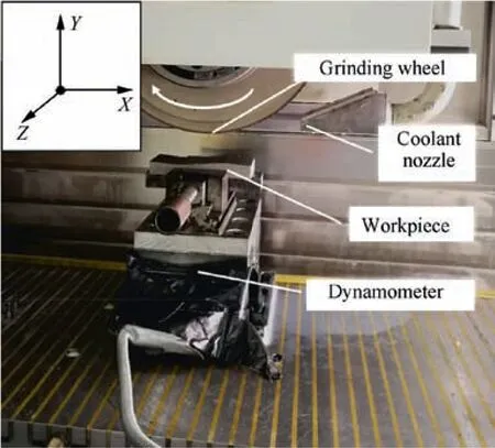
Fig. 2 Experimental setup of precision grinding process.

Table 1 Process parameters of precision grinding.
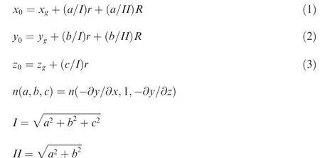
where ∂y/∂x and ∂y/∂z is the normal vector of equation in X-and Z-axis direction,r and R are the arc radius and center radius of the arc diamond grinding wheel, as shown in Fig. 3 respectively. In case that a plane wheel is used, i.e. r=0, the machining path of grinding wheel can be simplified to Eqs.(4) and (5):

Fig. 4 shows the freeform surface partially processed according to the abovementioned parallel grinding method and machining path calculation.As shown in Fig.4,the lower area is ground fully, while the top area was intentionally partially ground,with visible rough surface remaining.The roughness was resulted from incomplete removal of the as-built Fig.4 Fully and partially processed freeform surface by parallel grinding.surface features shown in Fig. 1(b). This workpiece was sliced to multiple pieces,thereby characterized to understand the surface morphology, dimensional accuracy and surface roughness.
2.3. Electropolishing
In general,Ti-6Al-4 V alloy is hard to electropolish,due to the fact that it is a kind of multi-phase alloy where different phases respond differently under a single anodic potential applied.20Less active phases will act as cathodic regions, causing more active phases to dissolve preferentially and thereby generating an uneven surface after electropolishing. Inclusions in the phase matrix can also aggravate uneven polishing, especially if the inclusions are inert, i.e. unable to be electropolished.Another reason is,the presence of a thin passivating TiO2film covering the surface of the alloy, which grants them superior chemical resistance.21The oxide film will quickly regenerate upon contacting with air or water,so prior mechanical polishing does not alleviate this issue.Being impervious to most common mineral acids, typical electropolishing solutions employ perchloric (HClO4) and hydrofluoric (HF) acids to remove the oxide film. However, both are extremely corrosive and hazardous.
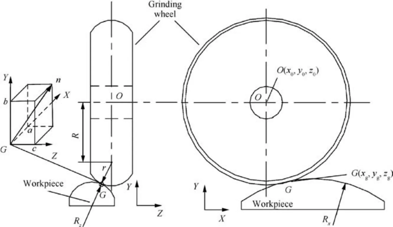
Fig. 3 Schematic illustration of parallel grinding of a freeform surface.
Currently, more research is conducted towards using of alcoholic acid mixtures as well as ionic liquid solutions to overcome this issue. Alcohols, such as methanol and ethanol, are known to de-stabilize the passive film in an anhydrous environment.22With the continuous film disrupted, stable anodic dissolution could be enabled on the bare metal surface. Ionic liquids are molten salts at room temperature. They act as anhydrous conductive media for the electropolishing.This prevents the continuous formation of the protective oxide film,as there is no oxygen evolution at the anode. In addition, it is reported that excess metal can be precipitated out from the solution above saturation.23
In this research, non-perchloric acid and non-HF based solutions were used to reduce the hazardous nature of the chemicals involved. An alcoholic solution containing chloride ion was adopted, to maintain moderate to high conductivity throughout the electropolishing process. Both as-built, partially ground and fully ground samples were electropolished in this study. Two solutions were proposed to investigate surface roughness and material removal. Both solutions contain aluminium chloride and zinc chloride dissolved in two premixed alcoholic solutions, (1) ethanol (EtOH) and isopropyl alcohol (IPA), (2) ethanol and n-butanol. The experimental conditions are listed in Table 2. The distance between the anode and the cathode (a Zinc plate) was maintained at 10 mm through all experiments. All experiments started with room temperature solutions. The temperature will rise as heat is generated from the electropolishing process. Constant voltage (30 V) and constant current modes were both investigated against the polishing duration, as part of the parameter optimization process. The expected reaction happening at the anode side would be the oxidation of metal into the corresponding metal ions:
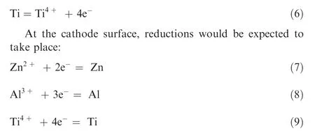
2.4. Characterization
GX51 Metallurgical Inverted Optical Microscope from Olympus Cooperation and Ultra Plus Field-Emission Scanning Electron Microscope (FESEM) from Carl Zeiss were utilizedto characterize both the surface morphology and crosssections of as-built and post-processed specimens. The dimensional accuracy was evaluated by a coordinate measurement machine (CMM), from Carl Zeiss. The surface roughness was measured by a stylus profilometer, Form Talysurf PGI 2540 from Taylor Hobson. Residual stress measurement was analysed through XRD (X-ray Diffraction) measurement using D8 Discover XRD from Bruker AXS Inc. This method is one of the techniques employed for surface residual stress measurement with the advantage of being non-destructive and with high accuracy.24For Electron Backscattered Diffraction(EBSD)measurement,a separate cross-sectional specimen from the various post-processed test pieces were prepared.Specimens underwent cross-sectional ion beam milling using IB-19500CP cross-sectional polisher from JEOL to attain a smooth surface for EBSD measurement. EBSD maps were captured by AZTEC software from Oxford Instruments which is coupled to Helios Nanolab 600i Focused Ion Beam (FIB)from Thermo Fisher Scientific. The re-crystallization fraction maps,which showed the deformed grains,were then calculated using HKL Channel 5 from Oxford Instruments.
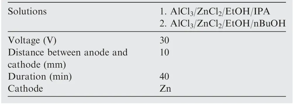
Table 2 Experimental conditions of electropolishing.
3. Results and discussions
The as-built surface was first ground by parallel grinding method, as discussed in Section 2.3. The surface quality was drastically improved compared to the as-built surface. Thereafter,both the as-built and the ground surface were electropolished to further understand the integrity of the polished surface quality. The results are detailed in the following sections.
3.1. Surface morphology
The change in surface morphology after grinding was evaluated by observing the cross-section and top surfaces of the ground specimen, as shown in Fig. 5.The partially melt particles on the as-built region are the main reason contributing to the large surface roughness.This partially melt layer was gradually removed during the grinding process and the change in roughness shows a strong correlation to the grinding depth.The surface roughness stabilized when the partially melt layer was fully removed,with tool marks becoming the main component contributing factor. Also, long and thin debris were observed in the valleys of the as-built region. This is due to intermittent grinding happening between the particles during grinding process.
In order to further improve the surface morphology, electropolishing was conducted on the ground surface, as well as the as-built surface for comparison. Fig. 6(a)-(d) shows the SEM images of as-built and various processed surface morphologies.The as-built surface by EBM was uneven and rough due to the partially melt particles resulting in the wavy surface(Fig. 6(a)). Electropolishing alone removed most of the partially melt particles and left behind low spatial frequency waviness on the surface, but was unable to remove the void zones between the particles (Fig. 6(b)). The surface after grinding became relatively flat but inherent tool marks were introduced(Fig. 6(c)). Through further electropolishing, the ground surface became relatively smoother, and at the same time minimizing the tool marks (Fig. 6(d)).
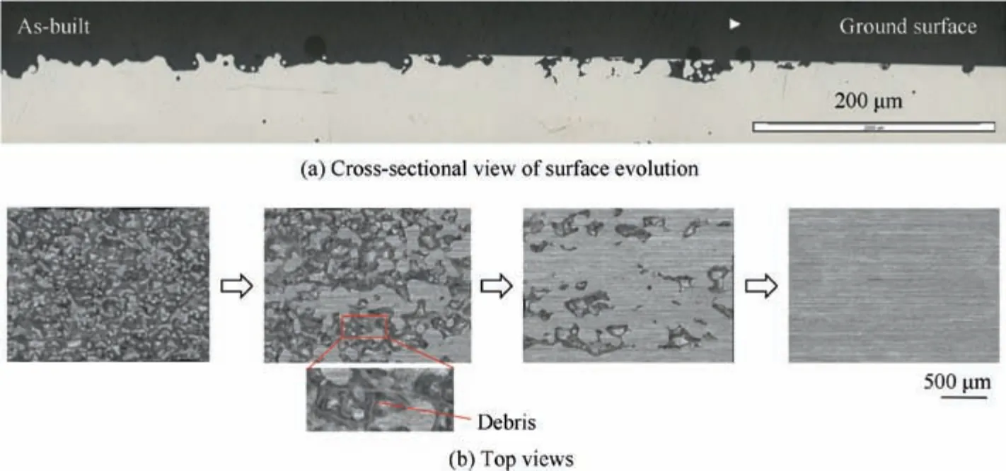
Fig. 5 Surface evolution from as-built surface to ground surface.
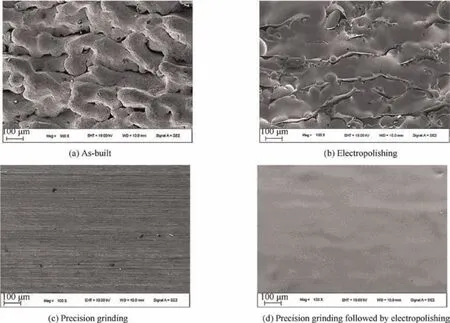
Fig. 6 SEM images of as-built and various processed.
3.2. Surface roughness and material removal
Besides morphological observation, it is equally important to quantitatively study the surface roughness achieved by different processes to correlate to the surface morphologies. Fig. 7 shows the surface roughness of specimens from the 4 processing conditions.The roughness of as-built surface varied greatly at different locations and was ranged 23-32 μm. After processed by electropolishing alone, the surface roughness was reduced to 21-28 μm.By precision grinding,the surface roughness can achieve approximately 2 μm. Through subsequent electropolishing, the surface roughness was further reduced to below 1 μm.
Fig.8 shows the effect of various grinding process parameters on surface roughness. Both surface roughness Raand Rzreduced with wheel speed, but increased with feed depth and feed rate.
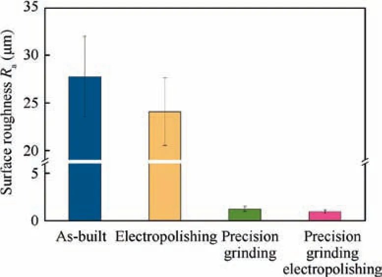
Fig. 7 Surface roughness achieved by different processes.
The surface roughness and material removal as a function of electropolishing time were evaluated. As shown in Fig. 9,Rareduced to 0.65 μm after 40 minutes of electropolishing.As material removal increased almost linearly with polishing time, the average material removal rate is estimated to be 1.1 μm/min.
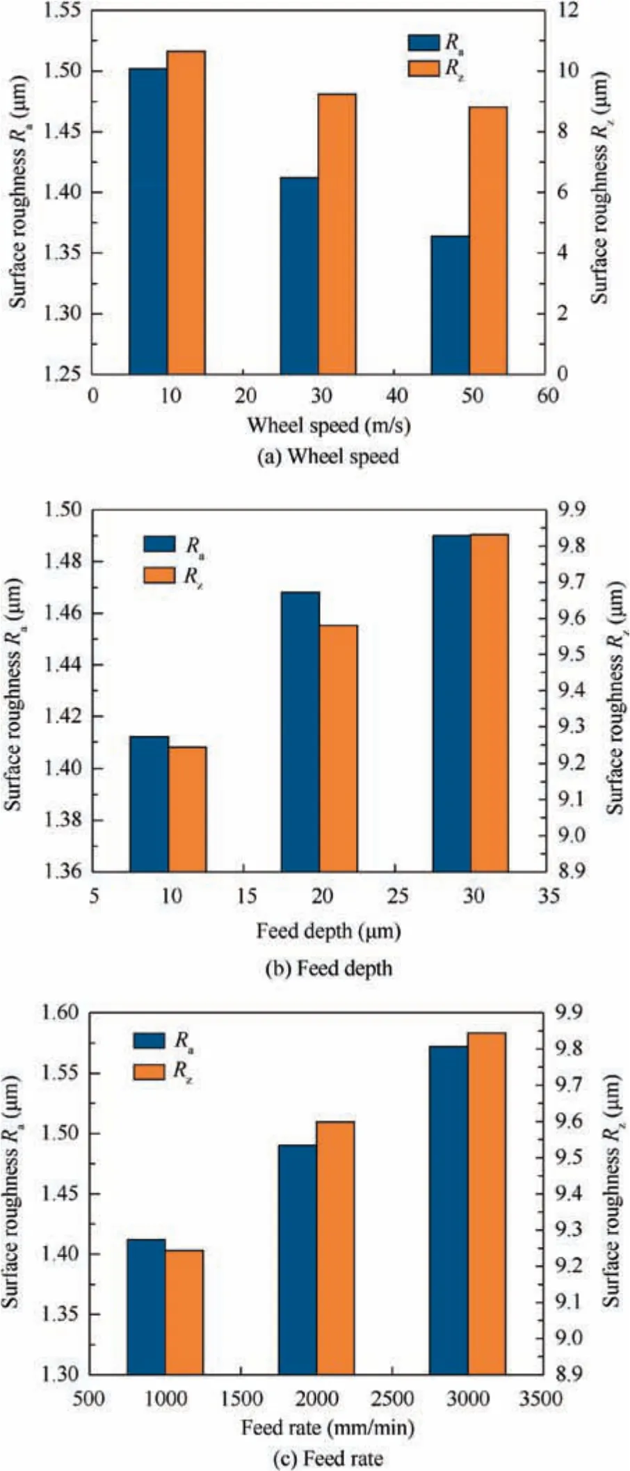
Fig. 8 Effect of various grinding process parameters on surface roughness.
The relation between surface roughness and material removal of as-built surface by precision grinding were al-so investigated.As shown in Fig.10,with the removal of partially melt layer, the surface roughness reduced rapidly in the first 100 μm of removed material and reached a plateau thereafter.Although Ravalue seemingly stabilized, small defects like pores and voids were still present from surface observation.Such defects were removed when the removed material reached 200-250 μm. This material removal depth is effectively estimated as the thickness of the partially melt layer.
3.3. Profile accuracy
The profile accuracy of the as-built and ground surface were evaluated.The profiles of the freeform surface before and after grinding were measured by the CMM at the same position with 5 mm offset from the edge (Fig. 11). As shown in Fig.11(a),about 0.8-1.0 mm depth was removed by the grinding process across the as-built surface.Fig.11(b)and(c)shows the profile error of as-built and ground surface,respectively.It is observed that as-built surface has profile error over 300 μm peak-to-valley(PV),which is usually not acceptable for practical application. With precision grinding, the profile error was greatly reduced to less than 7 μm PV. This exhibits huge improvement of surface profile error, with more than 95%reduction in PV as compared to as-built surface. In addition,considering the alignment error during the CMM measurement, the actual profile error could be even smaller. This level of surface profile error will be qualified for most engineering applications.The accuracy could be further improved through better control of environmental parameters such as process temperature and floor vibrations during the grinding process.
3.4. Subsurface quality
The subsurface quality was evaluated through cross-sectional observation with FESEM imaging. The morphology revealed serves as a reliable reference to understand the residual stress,subsurface damages and misorientations. The respective specimens were wire-cut and mounted using a slow cure epoxy.Next,a series of grinding with different grit of SiC papers were conducted,and the specimens were polished up to 0.05 μm colloidal silica suspension. Lastly, the specimens were etched using Kroll’s reagent through swabbing method for 10-15 seconds to reveal the microstructures. During the FESEM observation, secondary electron images were captured near to the surface where the post-processes were conducted.
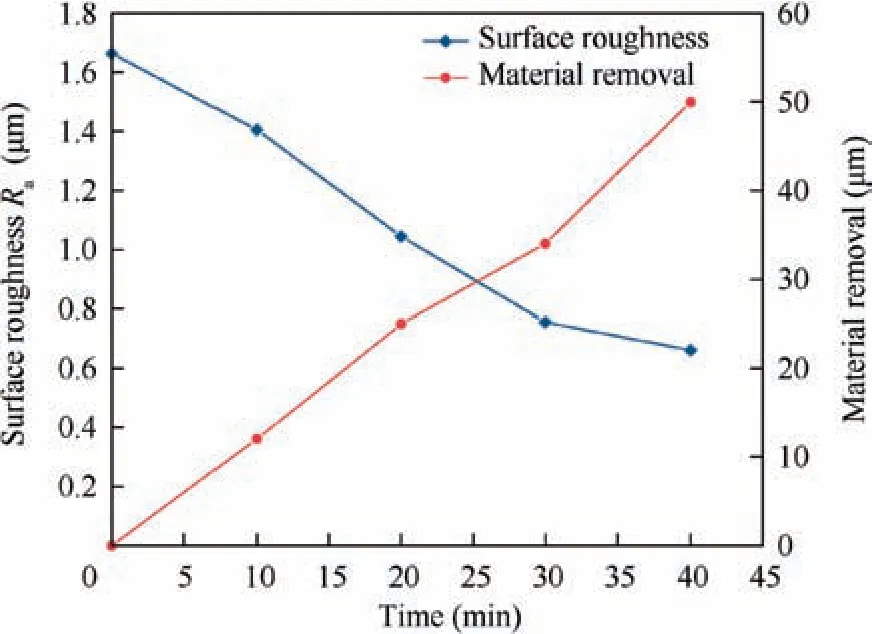
Fig. 9 Surface roughness and material removal as a function of polishing time for electropolishing.
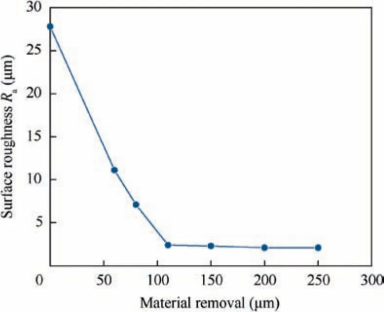
Fig. 10 Relation between surface roughness and material removal by precision grinding.
As shown in Fig. 12, it is observed that an approximately 2 μm deformed layer was induced by grinding process. This deformed layer was removed after subsequent electropolishing process, producing a damage free and stress-free surface.EBSD measurement was employed to understand the deformation distribution and dislocation density.It is observed that asbuilt and electropolished specimen have similar dislocation density,and ground specimen have significantly higher dislocation density in comparison. This is particularly true for the zone nearer to the ground surface, which is approximately 13 μm deep and is indicated as Zone 1 in Fig.13(b).The black areas in Zone 1,as shown in Fig.13(b),are due to severe deformations which have insufficient diffraction signals resulting in no detection. Such severe deformation in Zone 1 results in a high local misorientation as compared to Zone 2, 13 μm away from the top surface,as shown in Fig.14.These results are correlated with microhardness and residual stress in the next section.
3.5. Residual stress and microhardness
To evaluate the effects of different processes on superficial layer, the residual stresses of the respective surface produced by (1) as-built, (2) electropolishing, (3) precision grinding and (4) precision grinding followed by electropolishing, were measured by X-ray Diffraction method.25The penetration depth of X-ray was ~10 μm from each evaluated surface. In this analysis, longitudinal direction is defined as the direction parallel to wheel rotation vector, while cross direction refers to the direction perpendicular to that. The parameters used to measure the residual stress are listed in Table 3.
The results are summarized and plotted in Fig. 15. During solidification of melt pool in EBM process, some compressive residual stresses were left on the superficial layer of the as-built specimen. An increased compressive residual stress was generated by precision grinding (wheel rotation speed: 30 m/s, feed depth: 20 μm, feed rate: 2000 mm/s), especially along longitudinal direction. The residual stress induced can be attributed to both plastic deformation and elongation of grains.26
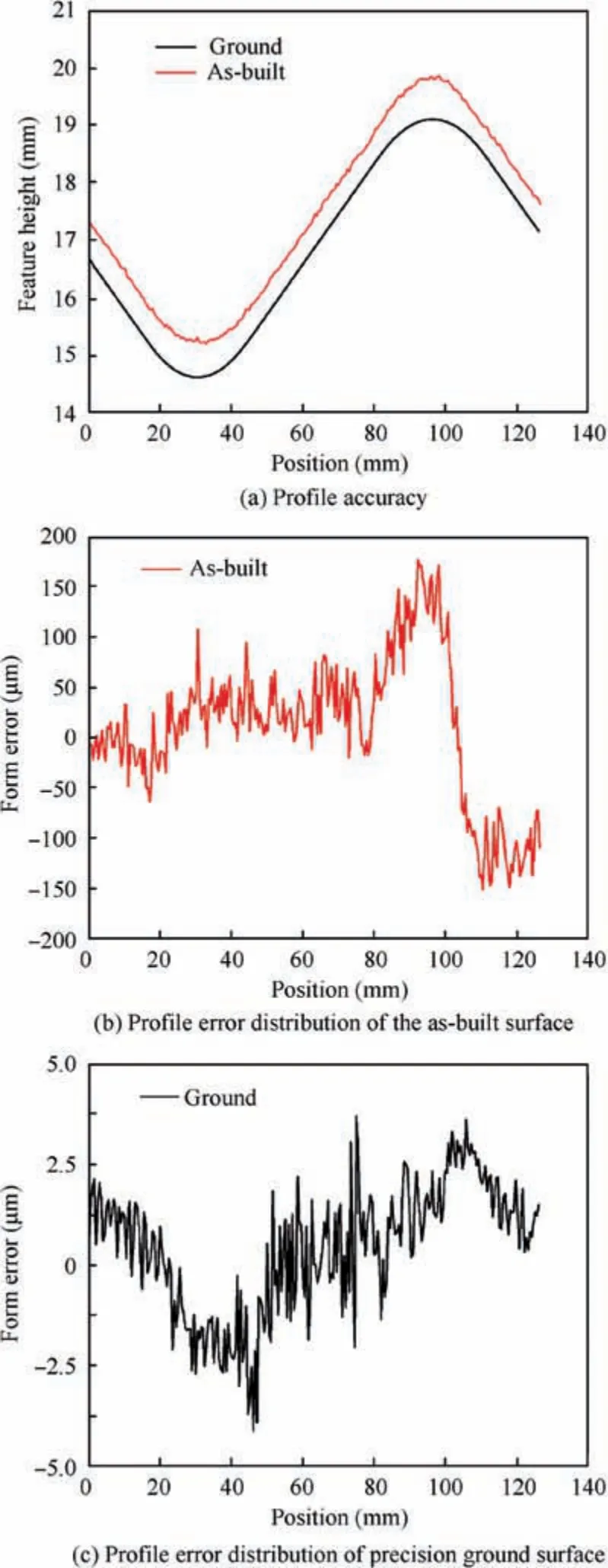
Fig. 11 Profiles of freeform surface before and after grinding.
Although residual stresses are normally considered as a negative effect which results in visible distortion of a part,the compressive residual stresses here may have a positive impact on fatigue performance which will bring benefits to Ti-6Al-4 V parts used in aircrafts and engines.27,28The compressive residual stresses can be extensively released by electropolishing. It should be pointed out that the residual stress values are not absolute and are only used for relative comparison,and whether the residual stresses were fully released needs to be further confirmed by observing the deformation of microstructures. In precision grinding, as shown in Fig. 16(a)and (b), it is further confirmed that the residual stresses increased with feed depth and feed rate at wheel rotation speed of 30 m/s.

Fig. 12 SEI cross-section observation of subsurface quality of various processing conditions.
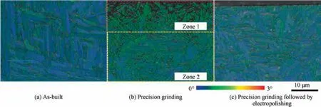
Fig. 13 EBSD mapping of various processing conditions.
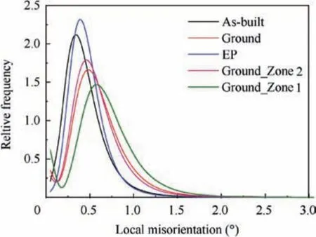
Fig. 14 Local misorientation profiles for EBSD mapping.
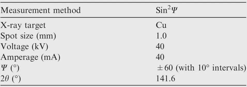
Table 3 Parameters for residual stress measurement.
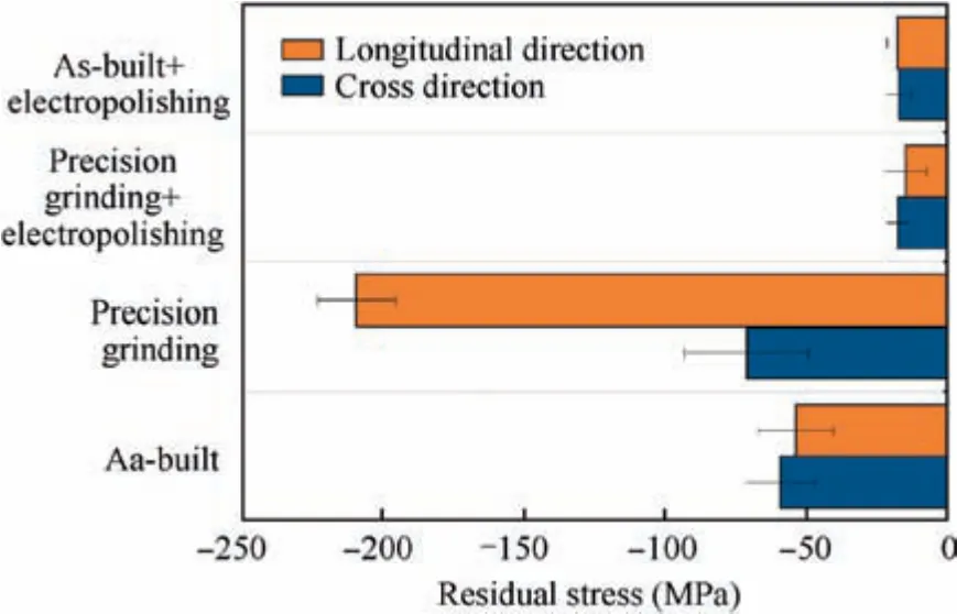
Fig. 15 Residual stress results by different processes.
Maiti et al.29have reported that grinding induces compressive residual stress that is beneficiary for aeronautical applications such as turbine blade. To verify this effect, the surface microhardness was evaluated with reference to the result of subsurface deformation and residual stress. The microhardness of as-built and solely electropolished surfaces were not evaluated due to the excessive rough surface conditions. Fig. 17 shows the surface microhardness comparison of ground surface and the surface from precision grinding followed by electropolishing. The surface processed by precision grinding followed by electropolishing can be considered as the undisturbed structure of Ti-6Al-4 V alloy since the deformed layer was fully removed. Comparing the two, the surface microhardness by precision grinding alone was up to 410 HV, increased by 7%.
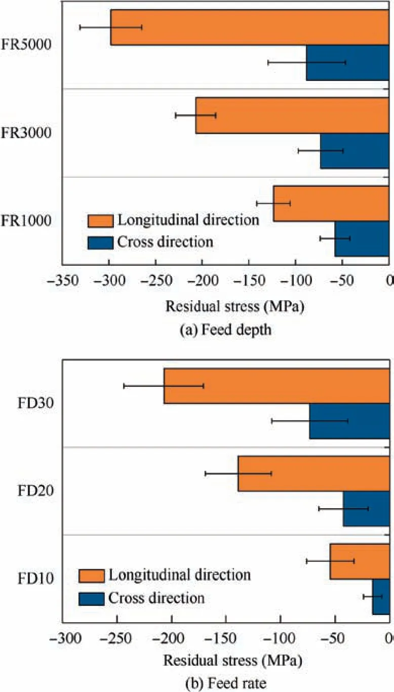
Fig. 16 Effects of feed depth and feed rate on residual stress.
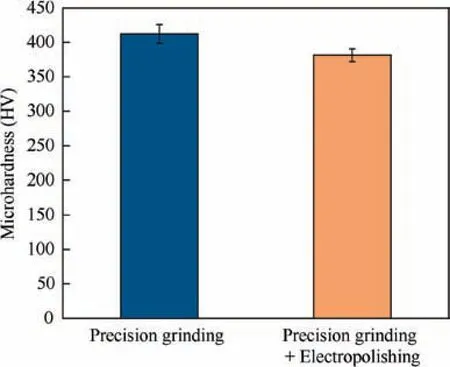
Fig. 17 Surface microhardness results.
4. Conclusions
In this paper,a comprehensive study on post-processed surface and subsurface integrity of EBM-ed Ti-6Al-4 V parts is presented. The interrelation between process parameters and surface/subsurface quality are clearly clarified both qualitatively and quantitatively for precision grinding and electropolishing.Below are the main findings to conclude this study:
(1) Precision grinding drastically improved the surface roughness and form accuracy from the as-built surface,especially when the depth of cut exceeds the thickness of the partially melted layer.
(2) Precision grinding followed by electropolishing was demonstrated with even material removal,without using hazardous perchloric acid nor HF, producing a significantly smoother surface with Raas small as 0.65 μm.
(3) Compressive residual stress induced by grinding serves to improve the superficial microhardness. Optionally,it can be relieved after electropolishing.
The research serves as reference for the integration of post machining processes with AM, or hybridized AM processes.Future investigation will be focused on the optimization of process parameters for such hybridized process.
Declaration of Competing Interest
The authors declare that they have no known competing financial interests or personal relationships that could have appeared to influence the work reported in this paper.
Acknowledgements
We would like to express our grateful thanks to Ms.Fern Lan Ng (Measurements and Characterization Unit, SIMTech) for the EBSD measurement, and Ms. Cho Cho Khin Ma (Measurements and Characterization Unit,SIMTech)for the residual stress measurement. The acknowledgement is extended to Mr.Seow Tong Ng(Machining Technology Group,SIMTech)for his kind support. The authors acknowledge the financial support from LiaoNing Revitalization Talents Program (No.XLYC1807230), A*STAR Industrial Additive Manufacturing Program: Work Package 3 (Electron Beam Melting, No. 132 550 4103)and Liaoning Natural Science Foundation Guidance Plan (No. 20180550171).
 CHINESE JOURNAL OF AERONAUTICS2021年12期
- CHINESE JOURNAL OF AERONAUTICS的其它文章
- Entropy based inverse design of aircraft mission success space in system-of-systems confrontation
- Nonlinear resonance characteristics of a dual-rotor system with a local defect on the inner ring of the inter-shaft bearing
- Failure mechanisms of bolted flanges in aero-engine casings subjected to impact loading
- Synchronized perturbation elimination and DOA estimation via signal selection mechanism and parallel deep capsule networks in multipath environment
- Improving seeking precision by utilizing ghost imaging in a semi-active quadrant detection seeker
- A high dynamics algorithm based on steepest ascent method for GNSS receiver
