An error analysis and optimization method for combined measurement with binocular vision
Yongkng LU, Wei LIU, Yng ZHANG,*, Junqing LI, Weiqi LUO,Ynze ZHANG, Hongwen XING, Lei ZHANG,
a Key Laboratory for Precision and Non-Traditional Machining Technology of the Ministry of Education, Dalian University of Technology, Dalian 116024, China
b COMAC Shanghai Aircraft Manufacturing Co Ltd, Shanghai 200120, China
KEYWORDS Aviation assembly;Combined measurement method;Error propagation;Large-size aviation component;Overall optimization
Abstract The accurate measurement of surfaces of large aviation components is vital for the assessment of manufacturing and assembly quality of such components.To satisfy the measurement requirement of large-size components, most current researches pay more attention to combined measurement methods utilizing different measuring instruments,but the related researches on error analysis and optimization methods are not taken enough attention. This paper proposes a combined laser-assisted measurement method with feature enhancement techniques,and it also develops an error propagation model of the main factors affecting the overall measurement error in detail.Firstly, the surface of a large-size component is measured by the measurement system at multiple stations. Secondly, a control point coordinate system is established as a bridge to unify all local measurement data into the global coordinate system. To improve the overall measurement accuracy, the pixel extraction error as a key factor causing the overall measurement error is analyzed in detail.Next,the error propagation model is established,and some optimization strategies of layout for minimizing measurement error and transformation error are researched. Finally, experiments are carried out to verify the effectiveness of the proposed method. The results show that the measurement error of the proposed method reaches 0.073% and 0.14% with a 1D standard ruler and a flat plate, respectively.
1. Introduction
Fast and high-precision measurement of large-size components is greatly important for the assessment of manufacturing and assembly quality in industrial fields such as aircraft manufacturing, shipbuilding, and construction of giant antennas,etc.1–5To meet the measurement requirements in terms of range and accuracy, the researches on measurement methods and multiple measurement instruments have become a hotspot over the past few decades. For example, the laser tracker is widely applied for the measurement of large components because of its large measurement range.6,7It can accurately give 3D coordinates of any point by tracking a cooperative target, but it cannot measure several points at a time. Besides,there are many other measurement instruments including theodolite,3total station8and indoor GPS.9However, such instruments can hardly acquire the surface geometry information of large components quickly and accurately. Photogrammetry has also attracted considerable research attention due to its robustness and ability to achieve full-field measurement.10Unfortunately,a series of marks need to be attached to the surface of the measured objects. Meanwhile, a laser scanner and laser radar do not need ancillary devices and targets in the measurement process,11,12but they have low measurement accuracy. Furthermore, binocular stereo vision13can quickly acquire surface geometry information of large components with high local measurement accuracy, and it has been widely used for industrial measurement.
In summary, a single measurement instrument can hardly acquire surface geometry information of large components with high accuracy and speed, simultaneously. Thus, a combined measurement method could provide a feasible solution that can achieve full-field measurement.14–17For example,different measurement instruments located in different stations could be combined to complete measurement tasks.18However, there are two common problems encountered with these two methods.Firstly,the surface of large-size complex components has to be divided into several regions and all local measurement data need to be transformed into a global coordinate system. Secondly, due to multi-station measurements of largesize objects,a series of imperfect measurements and coordinate transformations parameters can contribute to the overall measurement error.So far,most researches focus on different combined measurement methods involving global positioning and local measurement.19There are three typical registration methods20that can combine sets of data from different coordinate systems,including auxiliary devices-based registration,sequential registration and point-based registration. For auxiliary devices-based registration methods, an optical scanner and a robotic arm with mechanical tracking system are used to automate the measurement process and acquire measurements for the whole surface.21Shi et al.17established a 3D measurement method that integrates a scanner fixed on a robotic arm and a laser rangefinder calculating poses of scanner to measure the whole surface by moving the scanner straightly along the guide rail.However,the measurement range or overall measurement accuracy of both methods are severely influenced by mechanical auxiliary devices. For sequential registration methods, the whole surface is divided into several blocks that are combined into an entire component by common features of neighboring overlapping regions. The error will significantly increase with an increase of the number of sequential registrations. Global registration methods22do not require large mechanical devices or many markers that are attached to the measured objects.All local measurement coordinates can be unified into a global coordinate system through transformation matrices between the global coordinate system and each local coordinate system.This way, the accumulated error does not increase with an increase in the number of transformations. Point-based registration method is widely used in the field of large-scale measurement. To improve the overall accuracy of multi-stations measurement,the deployment optimization of common points,such as the number and the distribution, have been a research hotpot.23–25It is an effective method to reduce the registration error by improving the deployment of common points. Some researches claims that more than six common points and a uniform distribution are theoretically required. However, the researches on the deployment of common points for visual measurement have not been payed more attention, which are performed to reduce the overall measurement error.
In this paper, we propose a fast 3D measurement method that combines a binocular vision system and a high-precision global position system without the requirement of external mechanical devices. The binocular vision system can accurately measure partial blocks of the surface while being tracked by the global position system through several control points.The measurement range of the proposed method can be easily expanded and only one calibration between the vision system and global position system is needed. Besides, the research focuses more attention on the accuracy improvement with the optimization of layout of common points. Then, the error propagation model of combined measurement method is established and some optimization strategies are recommended to help minimize the overall measurement error.
The remaining sections of this paper are organized as follows. In Section 2,the measurement principle of the proposed methods and several calibrations of multiple systems are introduced.In Section 3,an error propagation model is established,and the influence of the layout of common points on overall measurement error is analyzed in detail. In Section 4, experiments are performed to verify the effectiveness of the proposed method. Finally, Section 5, some conclusions are drawn.
2. Principle of combined measurement method
The proposed combined measurement system of large components consists of a binocular vision system, a global positioning instrument and a feature enhanced system, as shown in Fig. 1. In this paper, two high-resolution cameras are chosen as the local measurement system (its coordinate system is called LMS) to acquire local geometry information. A laser transmitter with a rotary device is chosen as a feature enhanced system and it scans the whole surface using a laser strip. The laser strip helps improve the measurement accuracy of surfaces with few features. Besides, a laser tracker(AT960MR, Leica) is used as global positioning instrument to track the local measurement system and its coordinate system is considered to be the global coordinate system (GCS).The laser tracker has higher measurement accuracy compared with other large-scale metrology devices, such as theodolite and photogrammetry. To reduce time–cost and improve the overall measurement accuracy, several control points are fixedly connected to the binocular vision system and these control points are used to establish a median control coordinate system(CCS),which serves as a bridge for the global registration of measuring data.
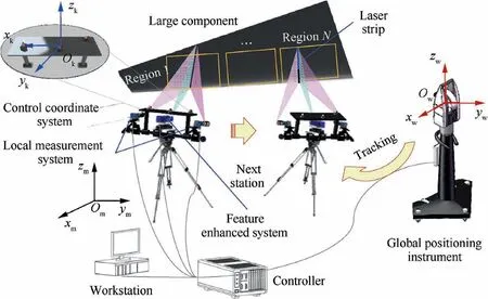
Fig. 1 Combined measurement system of large aviation components.
At first, the transformation relationship between LMS and GCS is established. Then, the transformation matrix between the control coordinate system and global coordinate system is calculated. Based on above two transformation matrices,we can obtain the transformation parameters between the local measurement systems and control coordinate system. Meanwhile, the stereo vision system is moved to another measuring station, which is positioned by the global positioning instrument by several control points.In other words,the global positioning instrument can track the CCS through only several control points and unify all 3D coordinates measured at different local stations into the global coordinate system. The detailed scheme is shown in Fig. 2.
2.1. Local measurement of measured object
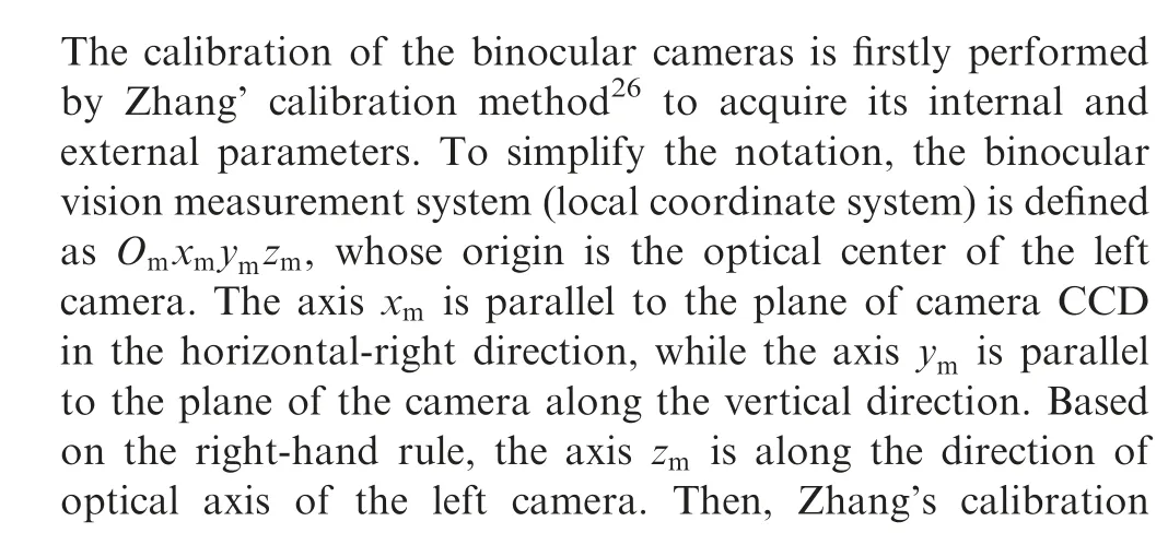
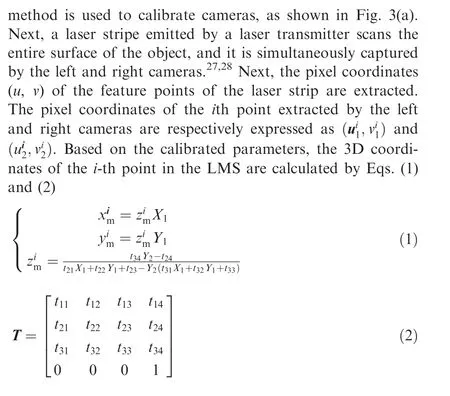
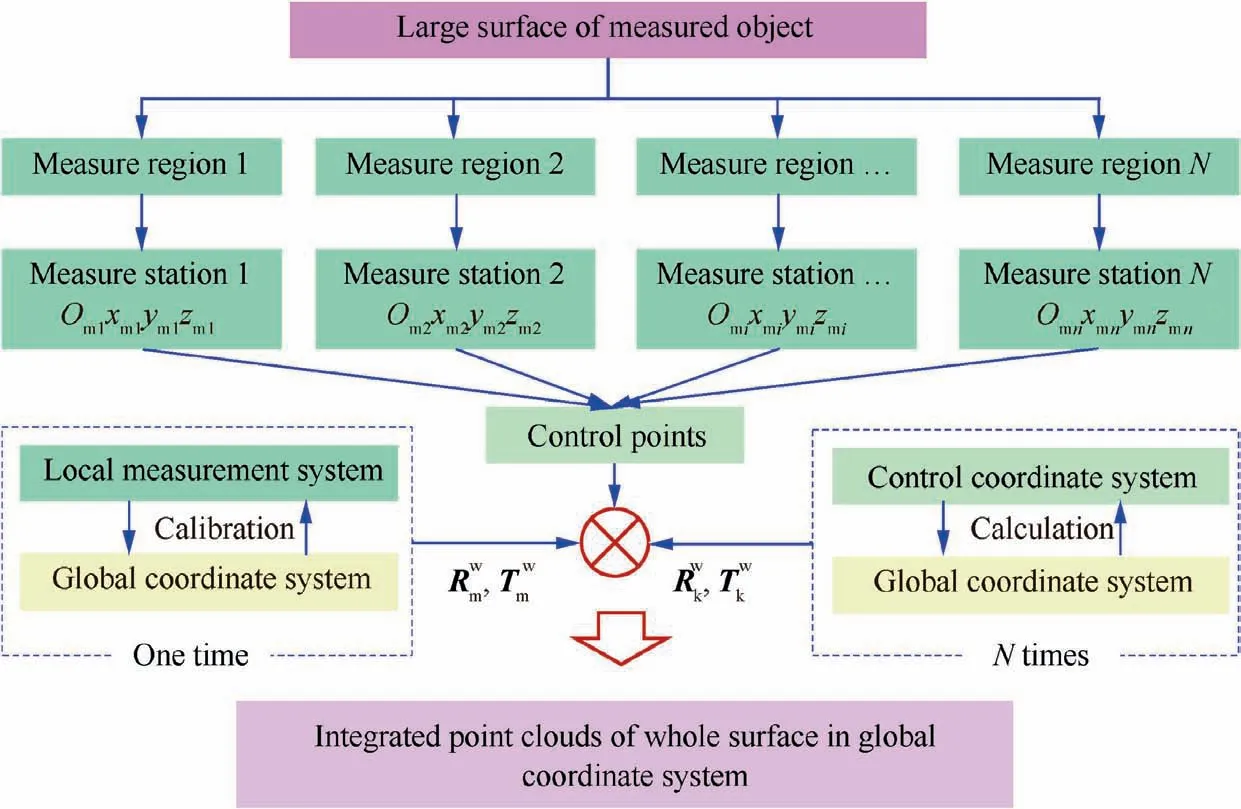
Fig. 2 Scheme of combined measurement method for large components.
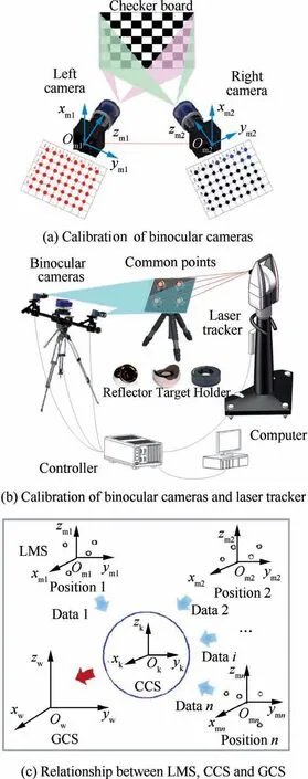
Fig. 3 Calibration of multiple coordinate systems.
where X1=(u1-u01)/fx1, Y1=(v1-v01)/fy1, X2=(u2-u02)/fx2, Y2=(v2-v02)/fy2. (u01; v01) and (u02; v02) are respectively the principal point coordinates of the left and right cameras. (fx1;fy1;fx2;fy2) are respectively the equivalent focal length of the left and right cameras. Trepresents the transformation parameters of binocular cameras.
The surface of the large component is divided into several regions, which are separately measured by local measurement system at different stations.16By solving Eqs. (1) and (2), 3D coordinates of all points in the surface can be calculated.Each series of coordinates of all points from one measurement station represents a point group and all point groups are defined as M.
2.2. Global registration of local measurements
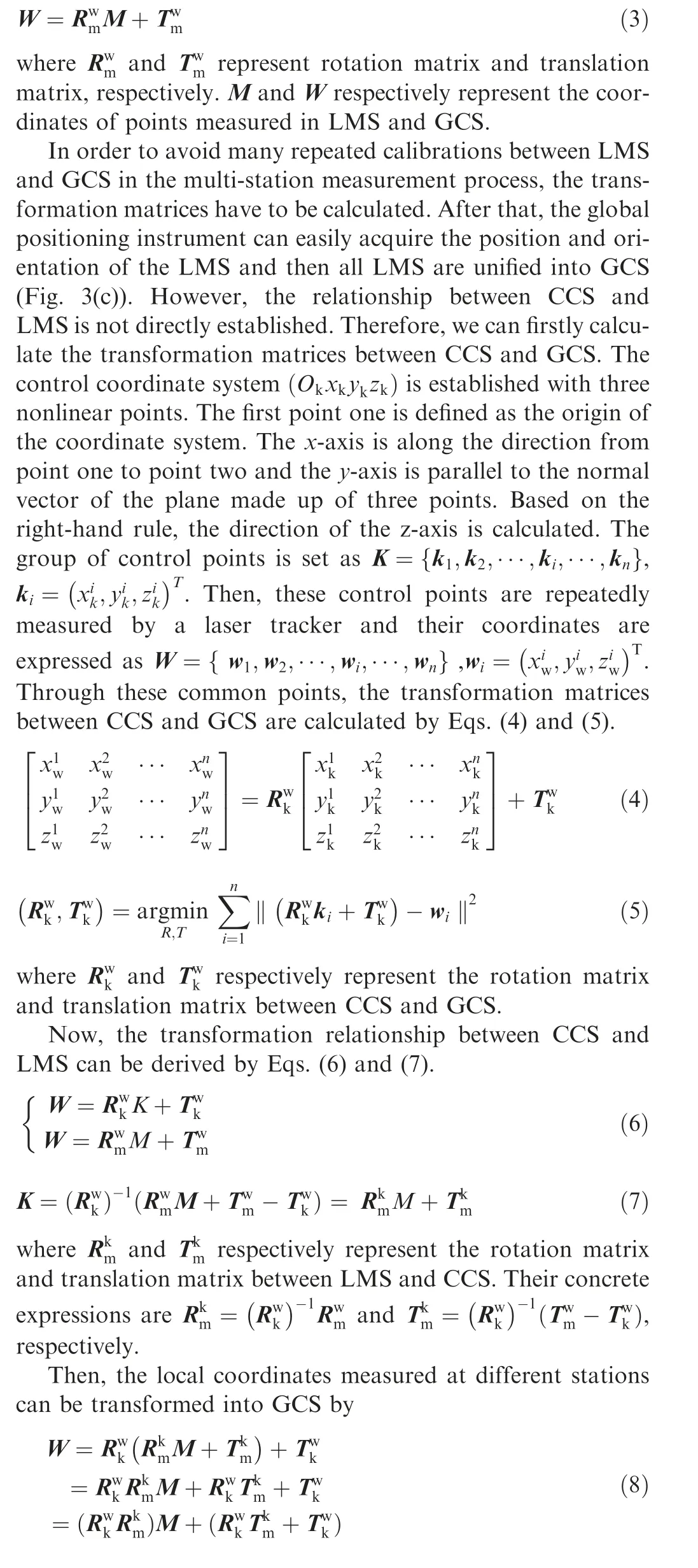
To unify all local point groups into the GCS,the calibration of multiple coordinate systems needs to be carried out. Firstly,the transformation parameters between LMS and GCS are calculated using SVD (Singular Value Composition) method29with a 3D artefact consisting of at least three spherical targets,as shown in Fig.3(b).Vision targets are set on the artefact and their 3D coordinates are acquired by the binocular vision system. Then, the spherical reflector targets of the laser tracker replace the vision targets, and their 3D coordinates are measured by laser tracker (Owxwywzw). Based on common target points, the transformation matrices of LMS and GCS are calculated by
3. Presentation of results
Through detailed analysis of related researches,30,31it can be found that the overall measurement error of the combined measurement method is closely related to the pixel extraction error as well as the layout of common points. Based on the error propagation law, an error propagation model of the combined measurement method is established. Then, the optimization strategies of common points are researched in detail.
3.1. Establishment of error propagation model
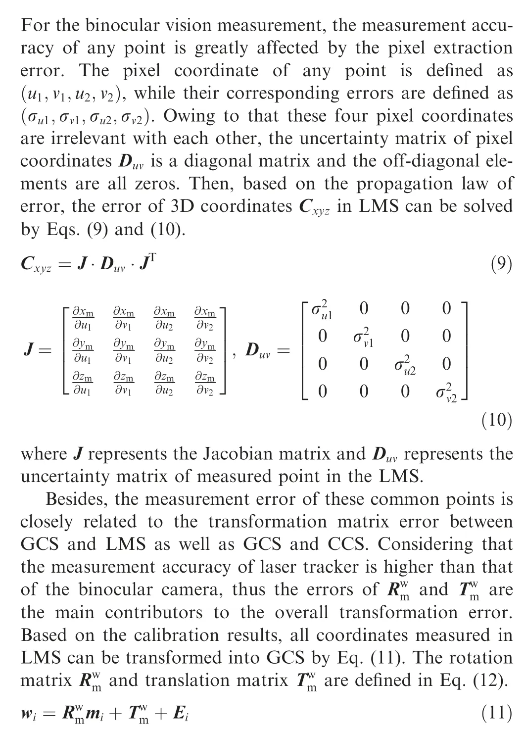


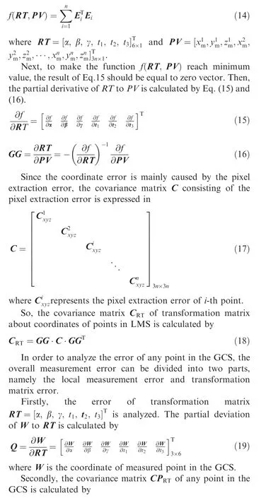

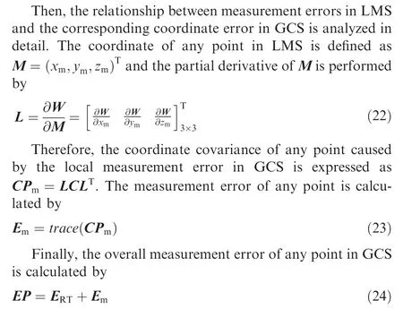
3.2. Layout optimization of common points
Through careful analysis of error propagation model of the combined measurement method, it is found that the layout of common points has a great influence on the overall measurement error. In this section, some simulations are performed to study the relationship between the measurement error and the layout of common points including the number,distribution space and distribution height of common points.
In the process of calibration, the variable-controlling approach is applied to research these influence factors of measurement accuracy. Several points among all the measured points are chosen to verify the accuracy of different layouts.In this simulation, the field of view of the binocular camera is 800 mm×600 mm. The initial height of the focal plane is 1275 mm and the initial depth of the camera is 200 mm. The calibrated results of the intrinsic parameters and extrinsic parameters are shown in Tables 1 and 2, respectively. Five points whose coordinates are (300, 200, 1200), (300, -200,1350), (-250, 200, 1200), (-250, -200, 1350) and (0, 0,1275),are chosen as the verification points to perform simulation calculations of the transformation parameters.
Firstly, the influence of the number of common points on the registration error is investigated. Some groups of pointswith different numbers are arranged in a space covering 500 mm×440 mm,whose distribution height is 1275 mm that is the same as the focal plane.Some groups of common points ranging from 4 to 32, are used to calculate transformation parameters between LMS and GCS. Five points are selected as the verification points. Then, based on the model described in section 3.1, some coordinate errors caused by different factors, including overall measurement error, local measurement error and transformation matrix error,are calculated. As seen in Fig. 4 (a), with the increase of the number of common points, the overall measurement error is gradually decreasing.Within a certain number range,the larger the number of common points become, the higher registration accuracy will get.The changes gradually tend to be smooth, when the number of common points reaches fifteen.

Table 1 Calibration results of intrinsic parameters of cameras.

Table 2 Calibration results of extrinsic parameters of cameras.
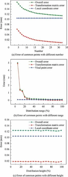
Fig. 4 Coordinate error of common points.
Secondly,the influence of the distribution range of common points on the error is investigated.A total of fifteen points with different distribution ranges (the percentage covering the field of view of the camera)are chosen to do the experiment,whose distribution height is also 1275 mm. The measurement errors are shown in Fig. 4 (b). It can be seen that within 35% of the field of view, the overall error of common points will decrease, as the distribution range increases.
Thirdly, the influence of distribution height of common points on multiple error is researched. Fifteen points is uniformly distributed in a space covering 550 mm×440 mm,with the distribution height ranging from 1175 mm to 1375 mm.The calculation results are shown in Fig. 4 (c). It can be observed that the distribution height has little influence on the overall coordinate error.
Based on the experimental analysis results of different influential factors, we can conclude that the number of common points should be at least fifteen and the distribution range should be larger than 35% of the field of view. The above results can provide measurement operators and other researchers with guide and inspiring suggestions to improve measurement accuracy of combined measurement system including binocular cameras.
4. Experiments
The proposed combined measurement system consisting of binocular cameras, a laser transmitter and a laser tracker is developed in the laboratory.As shown in Fig.5,the binocular cameras are two high-resolution cameras (VC-12MC-M/C 65 with resolution of 4096×3072,Vieworks,Korea)with a nominal focal length of 20 mm.The measurement error of the laser tracker (AT960 MR, Leica) is less than (15 μm+6 μm/m).There are many vision targets and spherical reflector targets(1.5 inches) used in this experiment. The experiments involves the calibration of multiple coordinate systems, the acquirement of coordinates, registration of global data registration,and the evaluation of measurement accuracy.
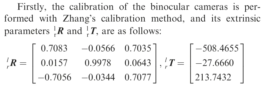
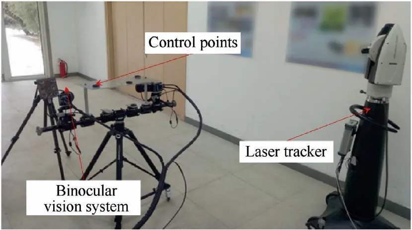
Fig. 5 Calibration of combined measurement system.
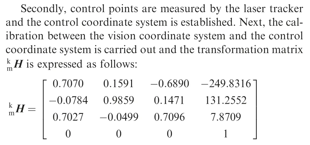
Thirdly,the local coordinate system at each measuring station is positioned by laser tracker with control points.Finally,all local coordinates are unified into the global coordinate system based on multiple transformation matrix.
To verify the effectiveness of the proposed method, a 1D standard ruler made of carbon fiber is used in the experiment.As shown in Table 3 and Fig.6,there are eight markers on the standard ruler with four standard lengths calibrated by National Institute of Metrology and its measurement uncertainty is 15 μm. The standard ruler is set at three locations and its markers on the two ends are separately measured by the binocular cameras. The measurement accuracy is affected by many factors,such as the distribution position,distribution height and measurement range of systems.Besides,some environment disturbances may also affect the measurement accuracy. Thus, the measurement error at multiple stations may be different from each other. The case exactly explains the importance and necessity of layout optimization for the improvement of measurement accuracy.However,it is difficult to meet with the layout requirement of all measured objects simultaneously. So, the maximum of measurement error is often used as the evaluation index of measurement accuracy.The comparative results are shown in Table 4 and the maximum of measurement error reaches 0.073%.
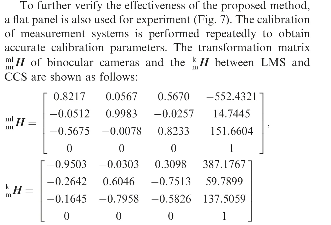
The large flat plate is divided into four regions that are separately measured at four stations.The laser tracker simultaneously tracks the binocular vision system.The laser strips on thesurface of the plate are extracted from images acquired by the vision system (Table 5). Next, all local coordinates are transformed into a global coordinate system to form a complete geometrical shape. The reconstruction result is shown in Fig. 8. All distances from each measurement point to the fitting plane are calculated. The ratio between the average projecting errors of measuring points and the size of flat plate(600 mm) is defined as reconstruction error which reaches 0.14%.

Table 3 Four standard distances of eight markers on a 1D standard ruler.
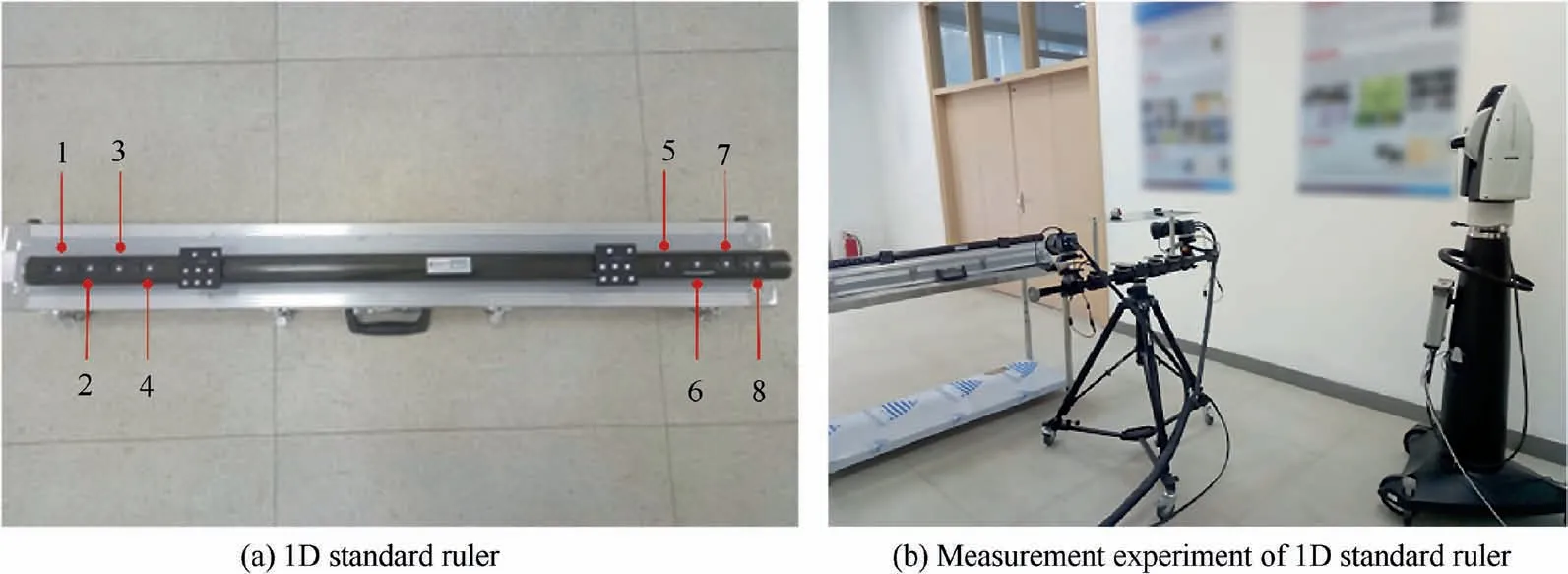
Fig. 6 Measurement of 1D standard ruler.
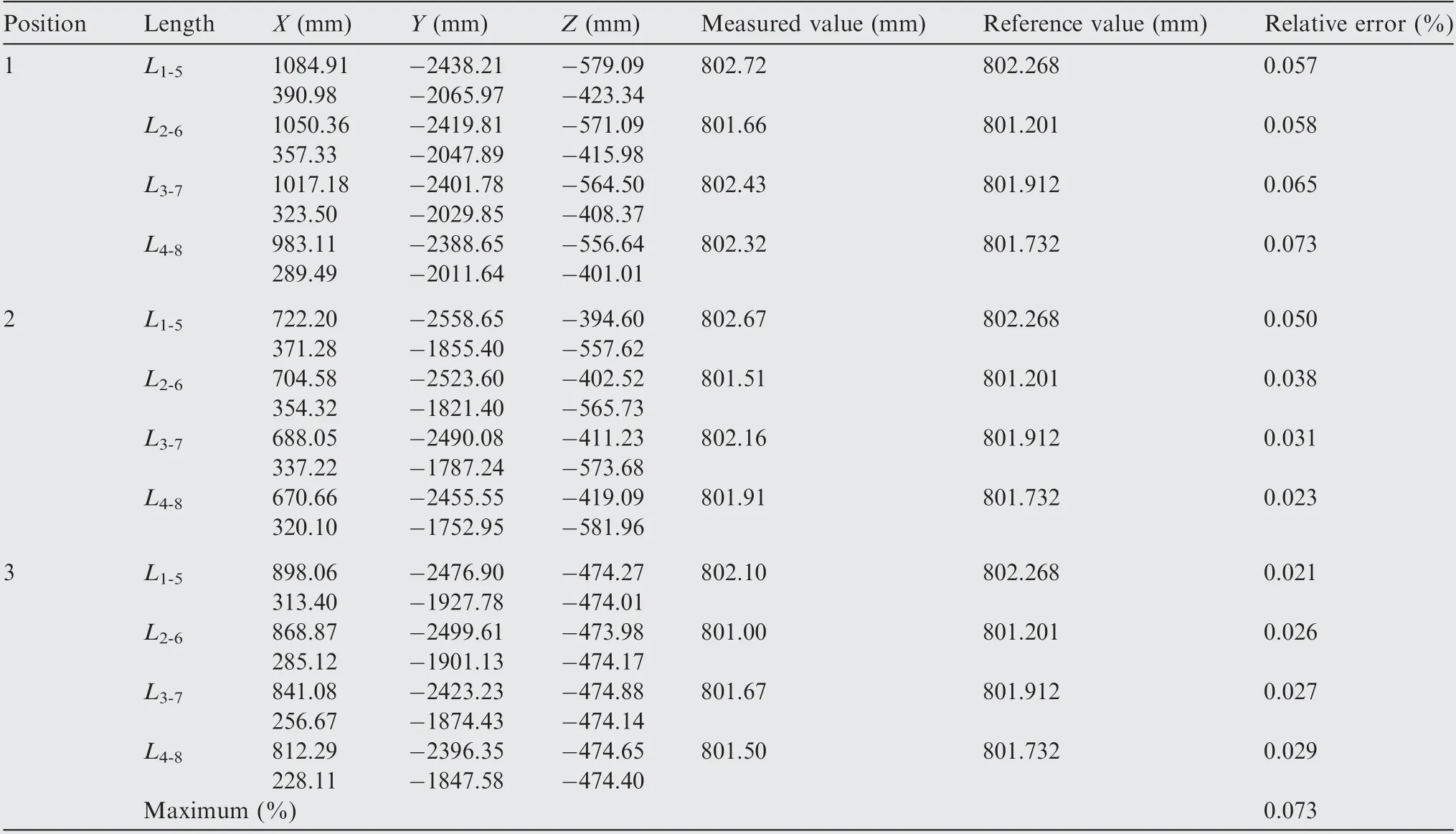
Table 4 Evaluation of measurement error of 1D standard ruler.
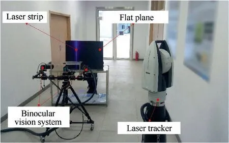
Fig. 7 Verification experiment of a flat plate.
To further verify the measurement accuracy of the proposed method, a measured experiment (Fig. 9) based on the strategies in section 3 has performed. In the experiment, the number of measured points is fifteen and their distribution space accounts for 35%of the field of views of cameras(Vieworks, VA-12MC-65, 4096×3072). At first, these points aremeasured by the laser tracker and then the distances between points are calculated. The maximum permission error of the laser tracker (Leica AT960-MR) is lower than (0.015 mm+0.006 mm/m). Therefore, the measured results of laser tracker are regarded as reference. Then, the combined measurement system measures local points at multiple positions to complete the whole measurements. Next, the coordinates of points and distances between points are calculated based
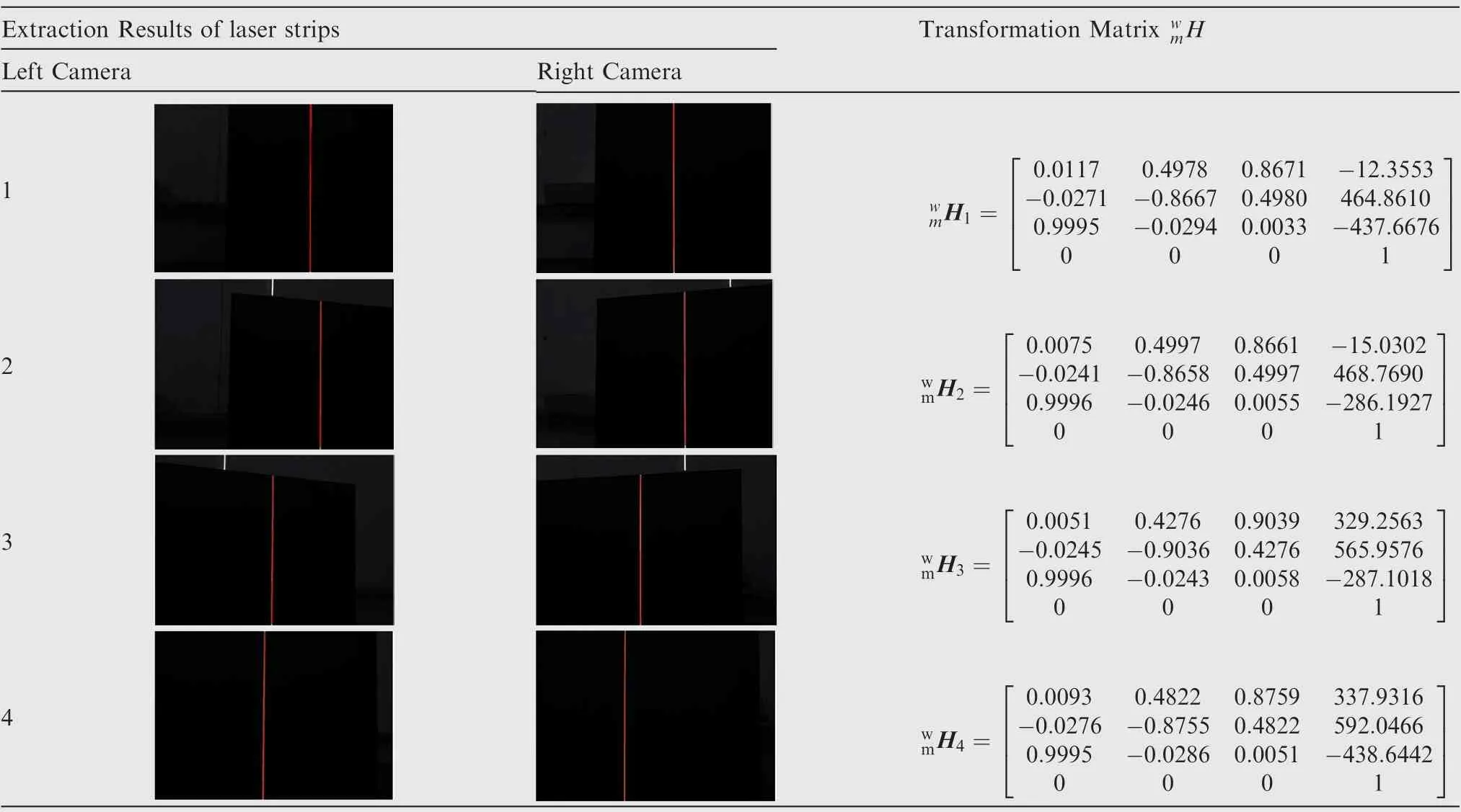
Table 5 Results of feature extraction and transformation matrix at different stations.
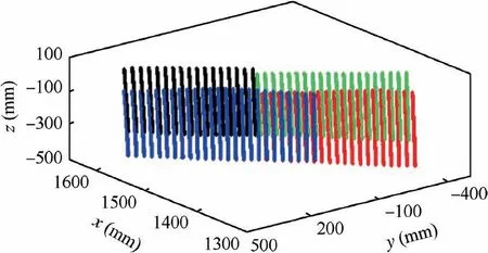
Fig. 8 Reconstruction result of the flat plate in GCS.
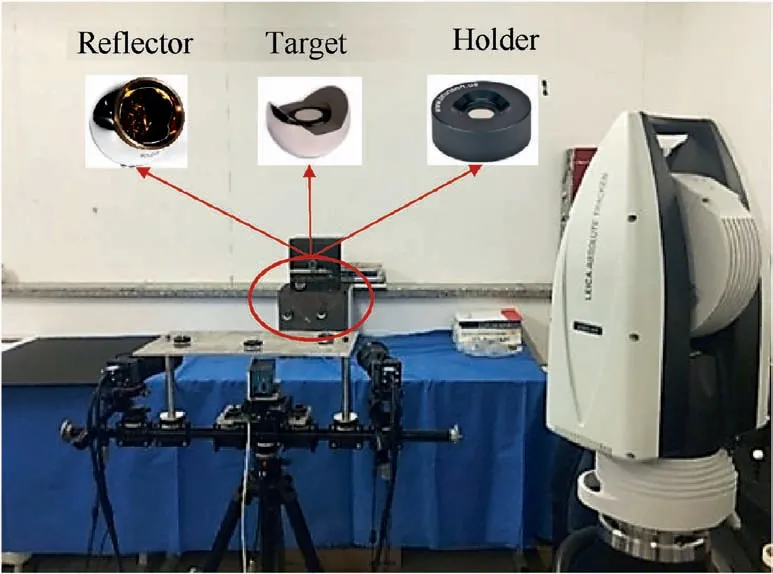
Fig. 9 Verification experiment with multiple measured points.
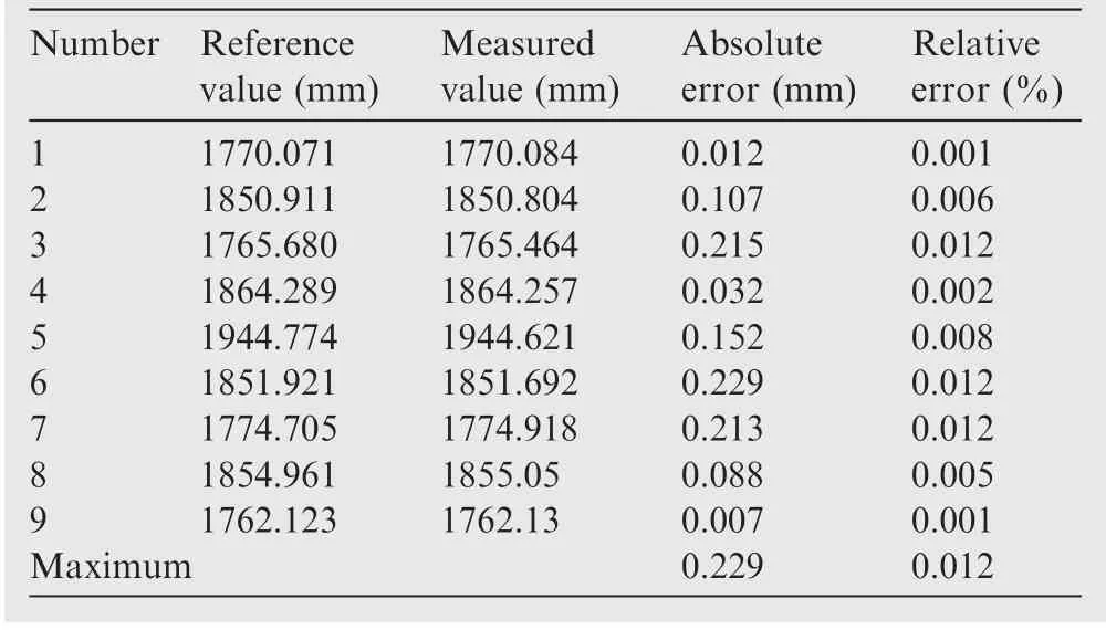
Table 6 Evaluation of measurement error with several measured points.
on the method in section 2. From the comparison results shown in Table 6,the maximum of relative error and absolute error are 0.012% and 0.229 mm, respectively.
5. Conclusion
(1) This paper presents a combined laser-assisted measurement method for the measurement of large aviation components without the need of auxiliary mechanical device. With this method, only one calibration between LMS and GCS is performed. All local measurements at different stations are unified into the global coordinate system through tracking several control points.
(2) Based on the error propagation law,the influence of the pixel extraction error of measurement points on the overall measurement error has been researched. An error propagation model has been established and used to carefully analyze the relationship between the pixel extraction error and overall measurement error in the global coordinate system. The relationship between the layout of common points and measurement error has been researched to derive some strategies for reducing the overall measurement error.
(3) The effectiveness of the proposed method is verified by a 1D standard ruler and a 2D flat plate.The measurement errors of the standard ruler(about 800 mm)and the flat plate(about 600 mm×800 mm)are 0.073%and 0.14%,respectively. Besides, the maximum of measurement error for measured points reaches 0.229 mm. In future works,more attention needs to be paid to the combined measurement method of large-scale measurement, other factors affecting the overall measurement error and the evaluation methods.
Declaration of Competing Interest
The authors declare that they have no known competing financial interests or personal relationships that could have appeared to influence the work reported in this paper.
Acknowledgements
This study was co-supported by the National Key Research and Development Project of China (No. 2018YFA0703304),the High-level Personnel Innovation Support Program of Dalian (No. 2017RJ04), Youth Program of National Natural Science Foundation of China (No. 51905077), Liaoning Revitalization Talents Program (No. XLYC1807086) and China Postdoctoral Science Foundation Grand (No. 2019M651110).
 CHINESE JOURNAL OF AERONAUTICS2021年10期
- CHINESE JOURNAL OF AERONAUTICS的其它文章
- Direct dynamic-simulation approach to trajectory optimization
- A strong robustness open-circuit fault diagnosis strategy for novel fault-tolerant electric drive system based on d-q-axis current signal
- Nonlinear vibration response characteristics of a dual-rotor-bearing system with squeeze film damper
- Ground maneuver for front-wheel drive aircraft via deep reinforcement learning
- Numerical simulation of a UAV impacting engine fan blades
- Recent advances in precision measurement &pointing control of spacecraft
