Recent advances in precision measurement &pointing control of spacecraft
Lin LI, Li YUAN, Li WANG, Ran ZHENG, Yanpeng WU,Xiaoyan WANG
a Space Optoelectronic Measurement and Perception Lab., Beijing Institute of Control Engineering, Beijing 100190, China
b Science and Technology on Space Intelligent Control Laboratory, Beijing 100094, China
c China Academy of Space Technology, Beijing 100094, China
KEYWORDS Disturbance-free payload;Micro-vibration suppression;Modern controllers or algorithms;Pointingcontrol system;Ultra-performance spacecraft
Abstract There exists an increasing need for precision measurement & pointing control and extreme motion stability for current and future space systems, e.g., Ultra-Performance Spacecraft(UPS).Some notable technologies of realizing Ultra-Pointing(UP)ability have been developed particularly for Ultra-accuracy Ultra-stability Ultra-agility (3U) spacecraft over recent decades. Usually, Multilevel Compound Pointing Control Techniques (MCPCTs) are deployed in aerospace engineering,especially in astronomical observation satellites and Earth observation satellites.Modern controllers and/or algorithms,which are a key factor of MCPCTs for 3U spacecraft,especially the jitter phenomena that commonly exist in a UPS Pointing Control System(PCS),have also been effectively used in some UP spacecraft for a number of years. Micro-vibration suppression approaches,however,are often proposed to deal with low-level mechanical vibration or disturbance in the microgravity environment that is common for UPS.This latter approach potentially is one of the most practical UP techniques for 3U tasks.Some emerging advanced Disturbance-Free Payload(DFP)satellites that exploit the benefits of non-contact actuators have also been reported in the literature.This represents an interesting and highly promising approach for solving some challenging problems in the area.This paper serves as a state-of-the-art review of UP technologies and/or methods which have been developed,mainly over the last decade,specifically for or potentially could be used for 3U spacecraft pointing control. The problems discussed in this paper are of reference significance to UPS and millisecond optical sensors,which are involved in Gaofeng Project,deep space exploration, manned space flight, and gravitational wave detection.
1. Introduction
The space Pointing Control System (PCS) of an Ultra-Performance Spacecraft (UPS) is designed to meet the fine pointing performance of milli-arc-sec stability, maneuver the spacecraft 20° in 15 s or less, and provide the capability for deployment from and retrieval by the space shuttle. The PCS objectives are met using Fine Guidance Sensors (FGSs) for attitude information, reaction wheel assemblies sized to provide both the torque required for maneuvering and the precision control torques during fine pointing, and magnetometers and magnetic torquers for momentum management. A digital computer is used to calculate the control law, the attitude reference, the momentum management law,and the command generator. The command generator shapes the acceleration and incremental angle commands to the PCS to limit structural mode excitation. Therefore, the environmental requests of the UPS make the requirements of sensitive payloads on the satellite higher than ever.1–3System payloads, especially UP optical instruments (such as highresolution cameras,4–6high-precision photoelectric detection instruments,7,8and high-precision sensors9,10), are also more sensitive to the environment onboard.
The ground resolutions of high-performance Earth observation satellites in Sun-synchronous orbit (~600 km) with a pointing performance of less than 1′′are typically between 0.1 m and 0.5 m, for example, the resolution of the American KH-12 satellite is 0.08 m,11and the resolution of Worldviewii is 0.46 m.12The resolution of Superview-1 developed in China is 0.5 m.13,14However, the resolutions of astronomical observation satellites are 1–2 orders of magnitude higher than those of high-performance Earth-pointing satellites, e.g., the angular resolution of the Hubble Space Telescope (HST) is 0.1′′,15,16and the pointing accuracy of the James Webb Space Telescope(JWST)is expected to reach 4 milli-arc-seconds.17,18In addition,in order to meet the fast response requirements of emergency-target observation tasks, a spacecraft is demanded to be able to swing rapidly in a very short period of time and have the ability of large-angle pitch maneuver.For example, the Pleiades19was designed based on the concept of platform-payload integration design with a maneuver of 60°in 25 s, and the attitude stability is lower than 10-4(°)/s.
UPS usually refers to Ultra-accuracy Ultra-stability Ultraagility (3U), and the precision pointing performance (in milliarc-sec) is the primary requirement. In an orbit-flying spacecraft,there will be a lot of interferences.For example,aerodynamics, micro meteor impact force, uneven gravity caused by the oblations of the Earth, and solar radiation pressure. In addition, the internal motion mechanisms of the spacecraft,such as solar array drive mechanisms, crycoolers, thrusters,mobile mirrors, reaction/momentum wheel assemblies,1,2,9,11etc.,will also produce interference forces.Although these interference forces are very small,the air in space is thin enough to change the fine pointing of the spacecraft. These low-level mechanical vibrations or disturbances in the space environment, typically occurring at frequencies from lower than 1 Hz up to a few kHz,11,20are called micro-vibrations onboard the spacecraft. Due to very tiny environmental damping(~1/25 of the ground) in aerospace, micro-vibrations could persist for a very long time. This will deteriorate the working environment of onboard instruments,for example,downgrading the precision of sensitive optical instruments or the pointing positional accuracy of space cameras. A typical example can be seen in the Space Interferometry Mission(SIM),where a space-based interferometer with astrometry and imaging capability must meet an extremely harsh positional tolerance(of an order of 1 nm across the entire 10 m baseline of the structure) to achieve astrometry requirements.
Many pointing control methods have been designed to protect UPS from the impacts of micro-vibrations and large-angle pitch maneuver in-orbit spacecraft. Primary pointing control methods for UPS, referred to as Multilevel Compound Pointing Control Techniques (MCPCTs) that have been developed and utilized in spacecraft, such as the HST, the JWST, the ACCESS satellite, and the Worldview satellite, can be seen in Refs. [21–25]. Typical MCPCTs consist of the hardware(coarse sensor, rate gyro, star tracker, fine guidance sensor,reaction/momentum wheel, etc.) and the underlying control algorithm. Many other technologies have also been designed as part of the 3U platform, which can ensure the ultraperformance of 3U spacecraft. The concept of Disturbance-Free Payload (DFP) has also been studied.
Overall, four kinds of technique can be classified for the ultra-performance of the PCS of a 3U spacecraft, i.e., multilevel compound pointing control based on a spacecraft attitude control system, advanced controllers and/or algorithms to solve the jitter phenomenon for 3U spacecraft tasks, microvibration suppression techniques based on vibration control theory, and a DFP satellite that benefits from non-contact actuators.In this work,these four types of key technology will be discussed, respectively, including characteristics, configuration design and features, advantages and disadvantages, etc.Noticeably,a special section is given thereafter for some novel and emerging methods by exploring DFP and benefits in noncontact actuators. This review will serve as a state-of-the-art(although not comprehensive) summary of the ultraperformance of PCS theory and/or methods,that have focused on 3U spacecraft over the last several decades. The relevant technologies and methods can provide valuable experience for 3U-performance spacecraft in future.
2. Multilevel compound pointing control techniques
2.1. Ultra-pointing control system
Multilevel compound pointing control techniques are commonly used in aerospace engineering providing high performance and stability, which include both the hardware and the underlying control algorithm,11,15,17,26as a typical UP pointing control system is shown in Fig.1.27,28With a Sun sensor, a gyro, a star sensor, and an FGS to acquire pointing information, a control command is given by the control computer to select an attitude sensor29,30and output the control torque of the attitude actuator, so as to achieve a UP performance. A main part of MCPCTs is the coarse sensor such as a Sun sensor. An FGS is usually located on an astronomical satellite, but it will not be adopted in other task satellites due to the cost, and a high-performance star tracker is good enough. In addition, the use of an FGS must consider the impact of micro-vibrations onboard a spacecraft, which will be a great price. For example, the micro-vibration problem of the HST has costed more than 200 million US dollars.15,26A main part of FGS design is the sensor Field Of View(FOV),e.g.,the FOV of the FGS located on the HST was just 2.3′×2.3′.31,32In general, the pointing performance is better if a narrow-FOV FGS is used in a spacecraft.
2.2. Pointing control and errors
The PCS stability has a low frequency (generally below 2 Hz)and a high frequency(above 10 Hz).In order to obtain Ultra-Pointing-Control (UPC) stability, the low frequency is based on the traditional attitude control, and the medium–high frequency is mainly restrained by the damping of the platform structure, the vibration isolator, the super static platform, etc.
Due to the influences of disturbance,noise,and other environmental factors, the pointing control errors of a spacecraft include many aspects. As for an optical spacecraft, pointing errors mainly include three factors,as shown in Fig.2;the factors that affect the Line-Of-Sight(LOS)direction include measurement error, control error, jitter error, etc., and MCPCTs and micro-vibration suppression are needed to jointly achieve 3U performance.The attitude maneuver ability of a satellite is determined by the capability of the actuator and the inertia of the satellite.In order to improve the maneuver ability,the inertia moment of the whole satellite should be minimized as much as possible,and a large-moment actuator should be used at the same time. Therefore, the high-agility direction needs to be realized through the platform-payload integrated design and the technology of the large-moment actuator.
2.3. Three-level control approaches
The development of a three-level control system is based on a spacecraft Attitude Control System (ACS). In general, ACS is a technology to acquire and maintain spacecraft orientation in space(i.e.,spacecraft attitude relative to a reference coordinate system). It includes attitude stabilization and attitude maneuver. The former is the process of keeping the existing attitude,while the latter is the process of reorienting the spacecraft from one attitude to another. However, before the process of attitude stabilization, there is usually an attitude acquisition process that uses a Sun sensor,a star tracker,etc.,for example,the initial attitude needs to be established when the spacecraft just enters orbit, and the attitude will be reconstructed when the spacecraft loses its normal attitude due to some accidental reasons.33–36Hence, the hexapod control system and the Fast Steering Mirror (FSM) control system are important parts of the three-level control system besides the ACS.36,37
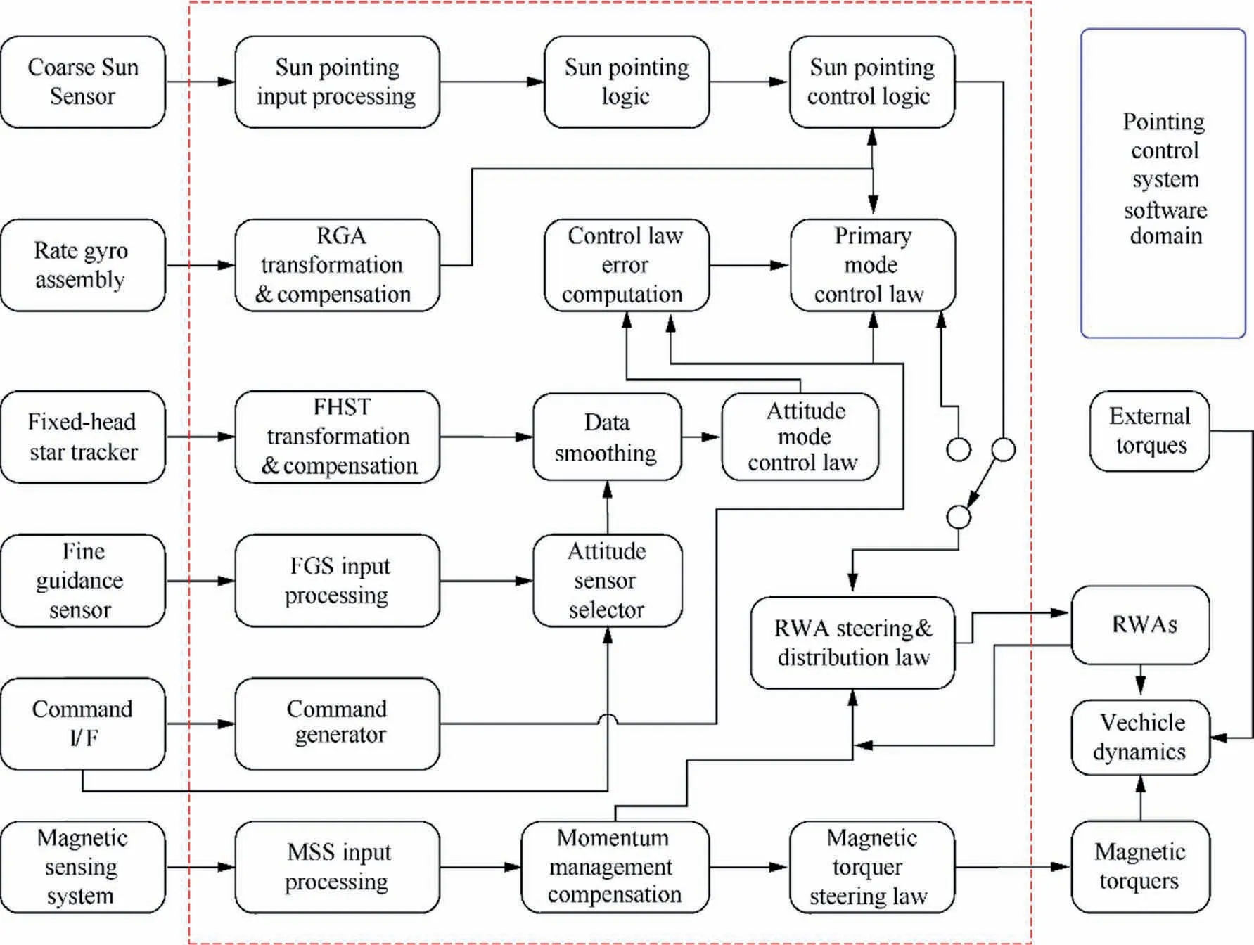
Fig. 1 Schematic diagram of the fine pointing mode of the HST.27,28
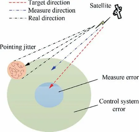
Fig. 2 Schematic of pointing errors.
A typical application of three-level control approaches is the pointing control design of the Access satellite,37one of the extra solar planetary exploration plans, which is planned to achieve 0.0001′′(1000 s) ultra-stability pointing control through a three-level control system.The first stage is platform attitude control, which uses Reaction Wheel Assemblies(RWAs) to make the body stability in the level of 0.1′′(yaw,pitch)and 5′′(roll)in 1000 s.38,39The second stage is a hexapod system, a six-degree-of-freedom telescope pointing system,which can stabilize the LOS at 0.001′′(1000 s). In addition,the hexapod system has the ability of vibration suppression.The third stage is the control system of the FSM, which realizes the pointing stability as 0.0001′′(1000 s). The aforementioned three-level control approach is shown in Fig. 3.37
The attitude performance of the platform is determined by star trackers, gyroscopes, and Inertial Reference Units(IRUs).40,41The Access ACS utilizes star trackers and IRUs for attitude determination, and reaction wheels for attitude adjustment.24Meanwhile, Proportional Integral Derivate(PID) control law is applied to the controller. The ACS loop topology per axis consists of a PID compensator, a secondorder bending filter to attenuate flexible modes, a momentum control loop for reaction wheel control, and an IRU (4 Hz bandwidth) for body rate information. The on-board attitude information is maintained and propagated as quaternions, by performing the kinematic integration using IRU data.In addition,a Kalman filter is used at a slower rate to correct the IRU drift and the estimated attitude quaternion by using star tracker measurements referenced to a star catalog. Access has strict requirements for pointing jitter,and any jitter above 10 Hz must be controlled within 0.0001′′. Thus, microvibration must be considered in the hexapod system,40of which a big problem will be discussed in Section 4.
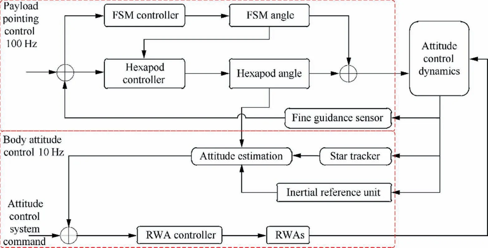
Fig. 3 Schematic diagram of the three-level control system of the Access satellite.37
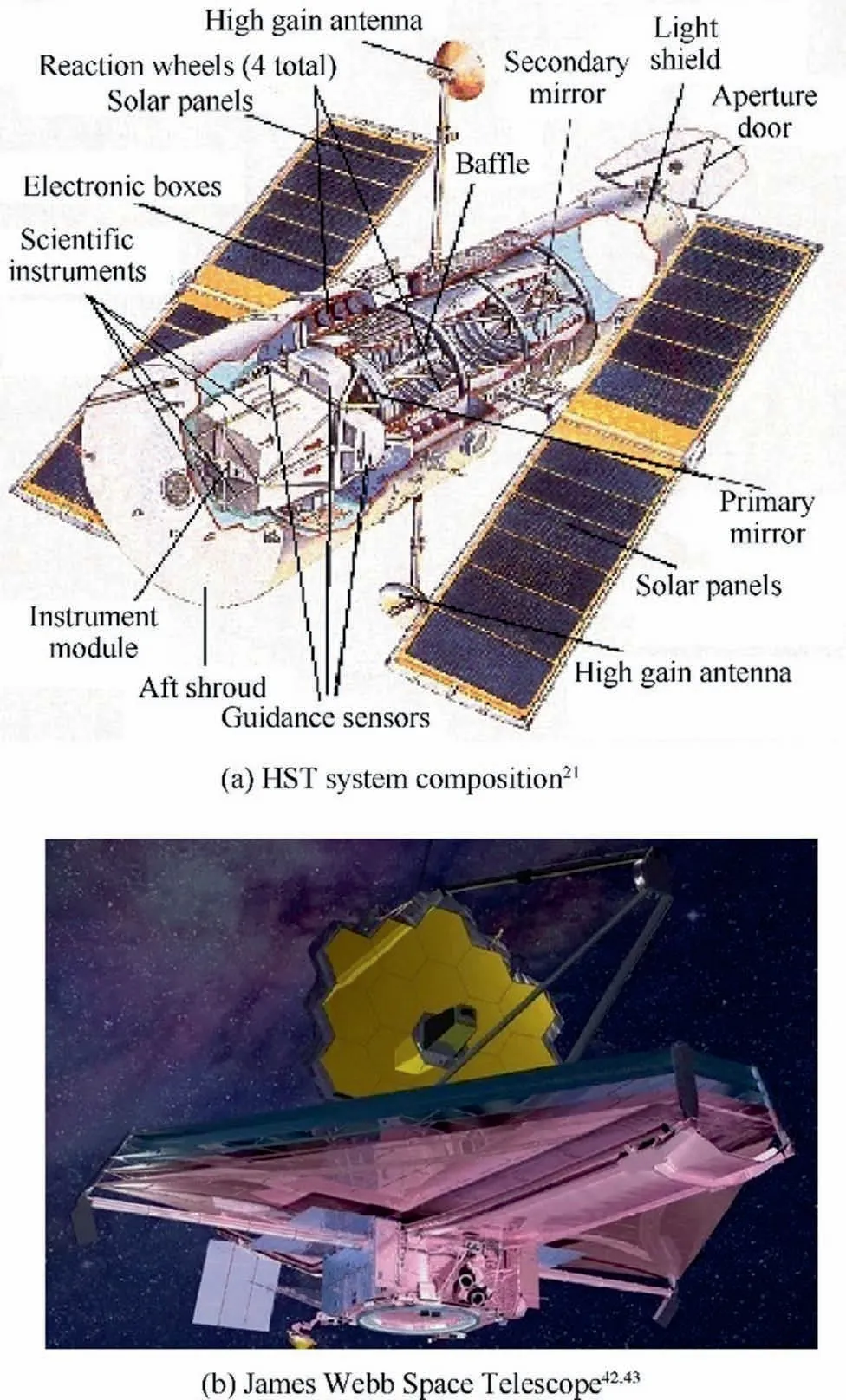
Fig. 4 Diagrams of the HST and the JWST.
Three-level control approaches have also been adopted in the HST21and the JWST42,43as shown in Fig. 4. The HST was launched in April 1990,and by April 2020,it has achieved the extra-long service capacity for the 30th anniversary in orbit.26,44The optical aperture of the HST is 2.5 m, the working band is arranged from ultraviolet to near infrared,and the diffraction limit-resolution can be obtained in the range of 100 nm to 2500 nm.8,45Four RWAs,46three FGSs,47six gyroscopes, and a DG-224 computer have constituted the core of the HST PCS. What’s more, a magnetic momentum system continuously unloads the flywheel, multiple Sun sensors for coarse attitude acquisition, and three star sensors for continuous attitude update.15The maximum output torque of an RWA is 0.82 N∙m,which can achieve 5(°)/min attitude maneuverability,45and the pointing accuracy is 90′′followed by the pointing stability 0.007′′for 95% of all 1 min intervals during an orbit.However,unexpected thermally induced disturbances originating in the solar arrays imposed deleterious effects on the pointing performance of the HST.15A NASA redesign of the onboard PCS brought the performance back to specifications during a majority of the orbit time.29,30As a result of this controller redesign effort, a wealth of flight data was collected and control design simulation models enhanced. During the course of the Marshall Space Flight Center (MSFC) Controls/Structures Integration (CSI) program, a number of universities and aerospace companies worked with MSFC researchers on fundamental research in advanced control theory, including the five groups represented in the HST PCS design improvement study.48–56The HST three-level pointing control system directly leads to the study of advanced controllers/algorithms for UPS, which will be discussed in Section 3.
The third stage,the control system of the FSM,will be discussed in the JWST’s pointing control system as shown in Fig. 5.22,23,57The JWST will be launched on an Ariane-5 rocket scheduled in 2021,57and because it won’t be in Earth orbit, it is not designed to be serviced by the space shuttle.At the Lagrangian 2(L2)point as shown in Fig.6,the JWST’s solar shield will block the light from the Sun, the Earth, and the Moon. This will help the JWST stay cool, which is very important for an infrared telescope. As the Earth orbits the Sun, the JWST will orbit with it – but stay fixed in the same spot around the L2 point with relation to the Earth and the Sun. Actually, satellites orbit around the L2 point, but don’t stay completely motionless at a fixed spot. The JWST realizes 0.0073′′pointing stability through three-level control.22A special structure called two-dimensional turntable was adopted to implement the FSM; a schematic diagram is shown in Fig. 7.
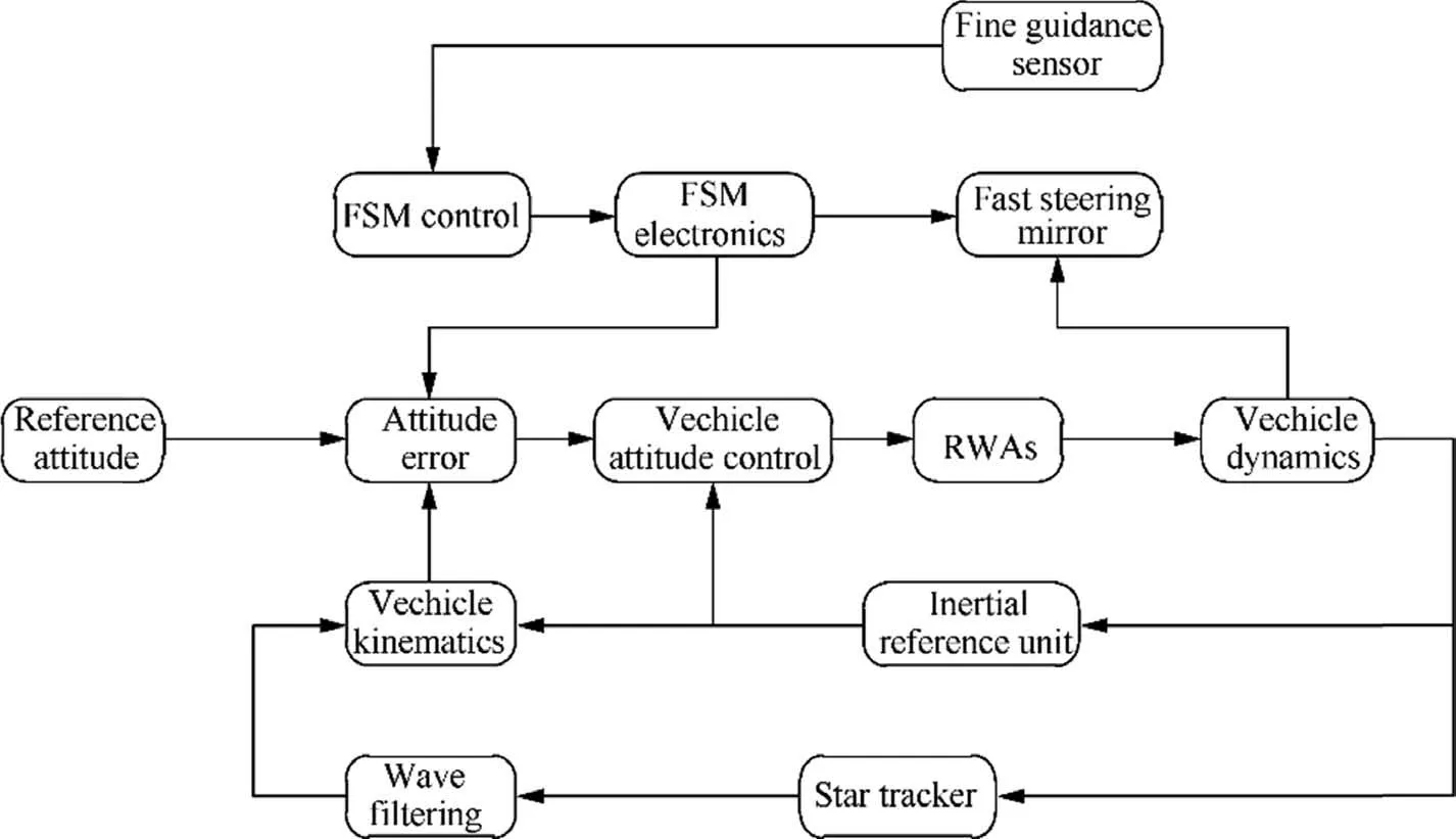
Fig. 5 Architecture of the JWST pointing control system.23
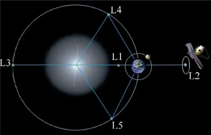
Fig. 6 Lagrangian points.
Through the FSM system, the pointing accuracy of the JWST is enhanced from 6.5′′to 0.0073′′and the control bandwidth is enlarged from 0.02 Hz to 2 Hz,which is a very big performance improvement. The FSM system includes a doubleaxis FSM and three FGSs. The FOV of the FGSs used in the FSM system is 2.3′×2.3′, and the detector has 2048×2048 pixels. A narrow-FOV and large-array detector enables it to achieve a very high pointing accuracy, but this is also the disadvantage that it must depend on the star sensor to seek the pointing direction.31,58
Generally,different stages of three-level control approaches have different priorities. The platform attitude control accuracy is 30′′and its stability is 0.1′′(1000 s yaw, pitch) and 5′′(1000 s roll)in a fine level,while the hexapod system’s accuracy is 0.001′′and its stability is 0.001′′(100 s).In this stage,the stability is likely to be 0.001′′considering the jitter of the LOS.As for the control system of the FSM, the third-stage accuracy will be 0.0001′′, and the stability will be 0.0045′′(1000 s). The jitter control is a challenging task in this level;the requirement stability should be 0.001′′so that micro-vibration in a spacecraft must be taken into account.
2.4. High-performance sensors
The coarse Sun sensor has been adopted for attitude measurement in early satellites.59,60With the development of largearray detectors and photoelectric detection technologies, a starlight measure approach has been developed particularly for high-performance spacecraft.61–64Generally,starlight measurement refers to the technology of imaging stars by photoelectric detection and calculating the attitude, pointing direction, and other information of a spacecraft based on the known stars.61,63Hence, it has better accuracy, reliability,and anti-interference than the Sun sensor method, and has been widely adopted in high-performance spacecraft.
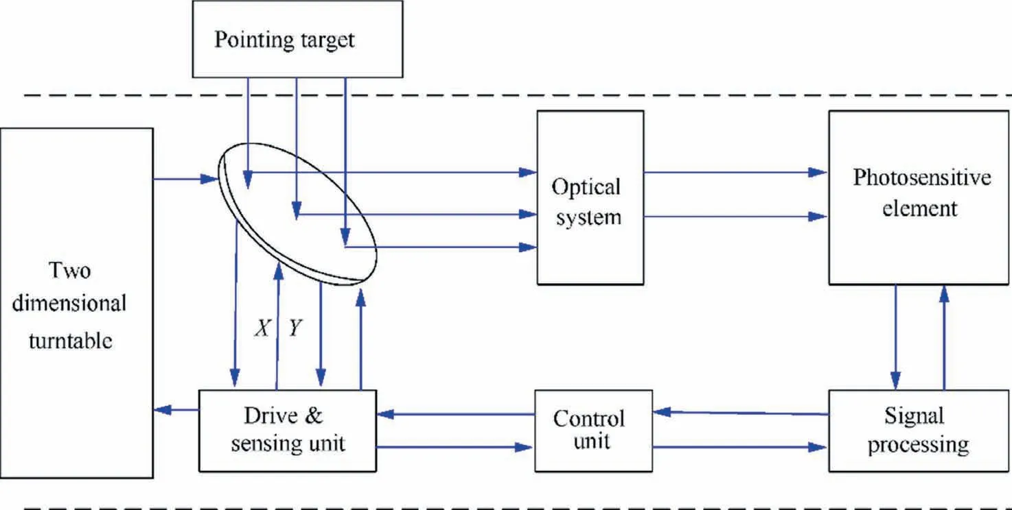
Fig. 7 Schematic diagram of the FSM.
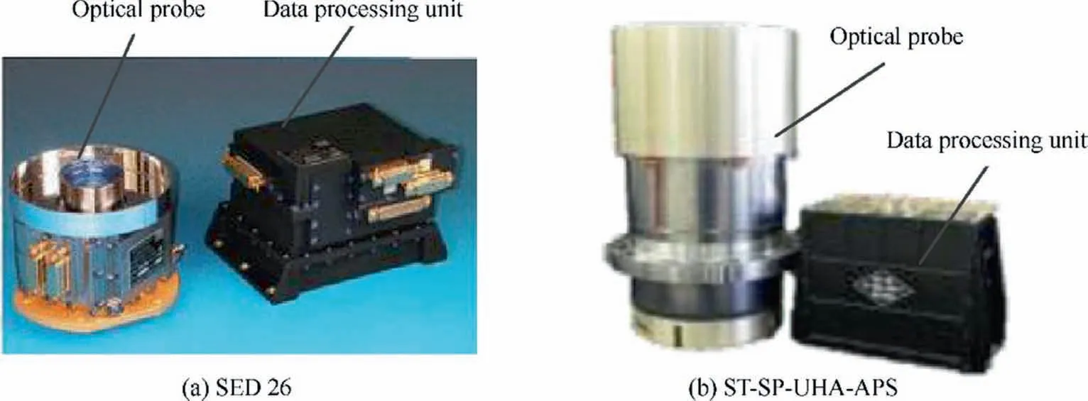
Fig. 8 Typical high-performance star trackers.64,66.
Typical star trackers with performance of sub-arc-sec stability are: ASTRO-APS65exploited by Jena-Optronik in Germany, SED 2666developed by SODERN Company from France as shown in Fig.8(a), AA-STR67studied by Galileo Company from Italy, and ST-SP-UHA-APS64exploited by Beijing Institute of Control Engineering (BICE) in China as shown in Fig.8(b). The FOV of ST-SP-UHA-APS is φ2°,accuracy is 0.3′′, and stability is 0.2(°)/s.64The optical probe and the data processing unit is separated by a split-structure design approach.Stability refers to the attitude dynamic acquisition performance that is instrumental in ultra-agility performance.This kind of star tracker usually chooses the scheme of a small-FOV and large-array detector to ensure the accuracy of a single star. The split-structure design method is adopted to guarantee high stability and low thermal drift. Whilst, the highly-precise-calibration method before and after launch is used to improve the measure accuracy.64
Fine guidance sensors31,47have been widely used in astronomical satellites, especially in space infrared telescopes, by utilizing an extremely long optic system focal length and a correlation algorithm to provide image motion for a vibration compensation mechanism.30,68The FGS is the component of an astronomical satellite that allows complying with the stringent pointing requirements of the mission. The main function of the FGS is to provide very precise attitude measurement to the satellite control loop during the scientific mode.68–70In general, the FGS is composed of three main components as shown in Fig. 9.68
The FGS shall be placed as close as possible to the focal plane array to minimize differential optical thermo-elastic deformation and maintain the FGS LOS as stable as possible with respect to the LOS. This configuration also allows for exploiting the high optical performance of a telescope necessary for detection of faint targets. The accommodation on the FGS in the payload module allows for limiting the contribution of deformation between the FGS and the instrument field of views.30,69As a necessary part of the guiding process carried by an astronomical satellite, a fine guidance star catalog is a key basis factor to determine absolute pointing of the LOS of a spacecraft. Selection of guide stars, catalog based storage capacity, division and regional search speeds are vital to realize functions and performances of fine guidance sensors.47,70
3. Advanced controllers and/or algorithms
Modern controllers and/or algorithms are a key factor of MCPCTs for 3U spacecraft, especially the jitter phenomena that commonly exist in a UPS PCS. The six modern control design approaches for the UPS PCS are now discussed. In the following contents,each controller design approach is summarized with an incisive description, including a control diagram and its characteristics. In addition, interested readers are encouraged to review those articles cited,in which the technical details and particulars of each design method are thoroughly covered.
3.1. Reduced-order model-based controller
Mark Balas led the Reduced-Order Model-Based Control Design52team at the University of Colorado in Boulder.Their design approach is based on Disturbance Accommodating Control(DAC)for large flexible structures.56A low-order version of DAC using a Reduced-Order Model(ROM)controller,a disturbance estimator, and a Residual Mode Filter (RMF)has been developed for the UPS PCS.52The theoretical development of the RMF and the application of ROM/RMF control to large finite element models of structures are given in Refs.71,72. The RMF concept has been developed for situations where(A)the control algorithm order is necessarily lower than that of the best available system dynamics model and(B)oscillatory modes in un-modeled dynamics that are thought to be ignorable are driven into instability by a high-gain control system. The ROM design73–75does not consider the effect of the control system on any ignored (residual) dynamics. Often,a number of these modes are driven unstable by the controller action.The ROM controller might be redesigned to include the interacting dynamics with the effect of increasing its order,but there is always a risk of creating new interactions.15The RMF is an alternative to a redesign cycle that provides independently designed, ‘‘add-on” compensation to stabilize the original ROM controller. This is the motivation for applying the technique to the UPS PCS. The RMF can be viewed as a feed-forward around the controlled structure or as a feedback around the ROM controller. The RMF output is subtracted from the sensor measurements, having the effect of opening the feedback path for the destabilized modes. This action returns the destabilized modes to their uncontrolled, stable response character. Its effect is to restore the dynamics used for the ROM controller design and reinstate its desired properties.15
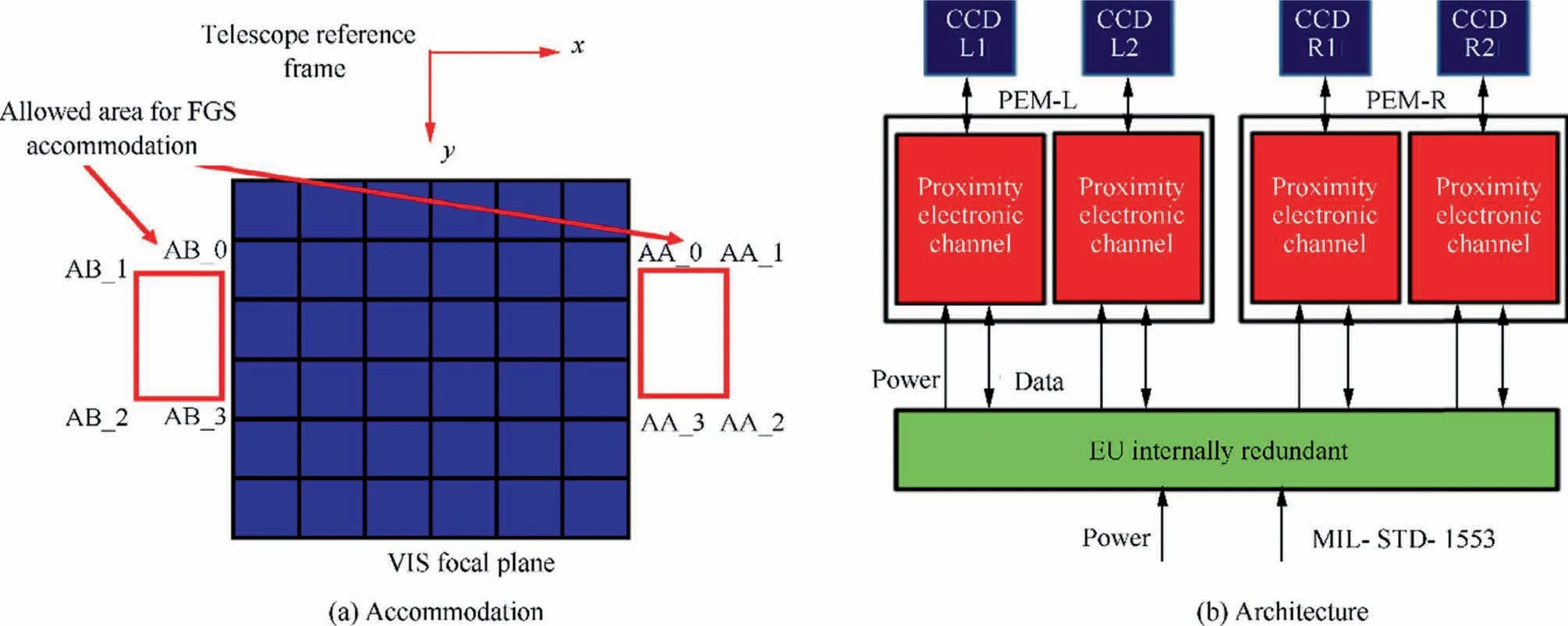
Fig. 9 FGS CCD accommodation and architecture.68
The controllability gram matrix provides a measure for comparing each mode’s excitability, i.e., its relative effect on the system performance. Looking within the spectrum of low-frequency modes,different modes have been collected into a test model to examine the singular values of the model’s gram matrix. Based on each mode’s relative effect on performance, the 1st (0.00 Hz), 3rd (0.68 Hz), 5th (3.0 Hz), and 14th (13.3 Hz) modes have been chosen. Among the lowfrequency modes,those having mode shapes out of plane with respect to actuator motion are excluded from the ROM.Instead,start with the premise that the ROM-based controller has been effectively designed to establish the necessary performance of the system.The design of the ROM-based controller uses a Linear Quadratic Regulator (LQR) augmented with an estimator.To remove the de-stabilizing residual mode interaction, add second-order residual mode filters around the ROM controller as shown in Fig. 10.76The addition of RMF compensation is straightforward, not iterative, and experimentally tested.76
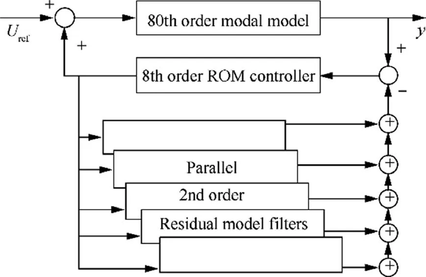
Fig. 10 Schematic of a linear controller of space large flexible structures.76
This design was implemented in NASA-provided simulation for evaluation, and eventually the technique was applied to the HST PCS. A balanced realization was used to reduce the model order from 118th to 18th for the DAC design. Its only difficulty involves ascertaining all of the modes defined as Q-modes.RMF design,then,primarily consists of choosing residual modes to compensate; RMFs are constructed to model residual modes extremely susceptible to interaction with the ROM controller. Assume that it either moves very slowly or is very stiff.Both of these rigid-body assumptions are good starting points; however, it seems clear that the flexible nature of the crane,76a necessary tool to assemble large structures in space, must now be considered.
3.2. Linear quadratic Gaussian-based approach
The Harris Corporation team, led by Emmanuel Collins,used a Linear Quadratic Gaussian (LQG)-based approach53to design a UPS PCS. The Harris team used Single-Input and Single-Output(SISO)composite models to develop LQG controllers based on the observation that the transformed plant is approximately decoupled. This implies that the performance achievable by the SISO designs should be close to that achievable by the MIMO design. These modes exist and should be accounted for in the controller design. The design for the UPS PCS LQG tracking/integral controller is posed as a disturbance rejection problem. The critical element of this design is to select a disturbance rejection filter so that the controller has a proper number of integrators (two) while achieving the desired tracking performance.Selecting a disturbance rejection filter so that it has the same number of integrators as that of the compensator is a natural inclination; however, this leads to an ill-posed problem since the design model would have uncontrollable, neutrally stable poles.53This methodology can be used to imbed a desired number of controller integrators in a modified plant model so that the corresponding LQG compensator actually contains no integrator. This precompensation strategy has been successfully employed on NASA structural control testbeds.77,78A separate LQG design is performed to accomplish the higher-frequency disturbance rejection once the tracking/integral control described above is completed.In this fashion,solar panel disturbances are compensated by the PCS. The disturbance rejection compensator acts on the closed-loop plant that includes the tracking/integral controller. This closed-loop plant does not contain the very low frequency dynamics that cause numerical conditioning problems. The disturbance rejection filter is designed with emphasis on rejecting disturbances at 0.11 Hz.15
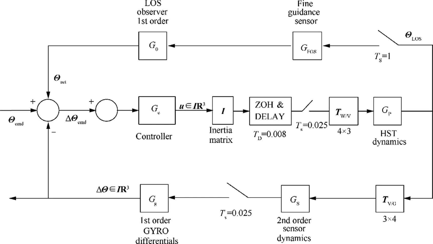
Fig. 11 Block diagram of control configuration for HST.79
A block diagram of the closed-loop control scheme is shown in Fig. 11.79The 4×3 transformation matrix Tw/vand the 3×4 transformation matrix TV/Gessentially decouple the PCS attitude controller into three parallel, single-axis loops. The original controller was essentially a PID controller that was not designed to attenuate the effects of the solar array disturbances TD. This controller has a tracking bandwidth of 0.1 Hz. It is desired to design a new controller Gcthat attenuates the effects of the solar array disturbances while maintaining the 0.1 Hz tracking bandwidth of the original PID controller.79By using the original PID controller as the baseline, the disturbance attenuation requirements of the LQG controller can be formulated. The disturbance rejection at 0.1 Hz is improved by at least a factor of 30 (29.5 dB), and the disturbance rejection at 0.6 Hz by at least a factor of 10(20 dB).
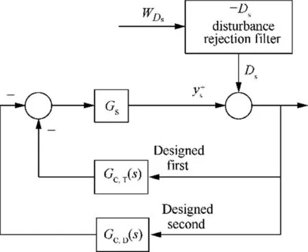
Fig. 12 Block diagram for designing disturbance rejection.79
The disturbance rejection compensator acts on the closedloop plant, which includes the tracking controller GC,T(s) as shown in Fig. 12.79This closed-loop plant does not have the very low frequency dynamics that cause numerical conditioning problems. The tracking controller GC,T(s) and the disturbance rejection controller GC,D(s) can be implemented as a single compensator in the forward path Gc(s), which is beneficial to increase the gain on the tracking controller GC,T(s)before designing the disturbance rejection controller. Hence,GC,T(s) in Fig. 12 was replaced by βGC,T(s) for some β>1.
3.3. Analytically and numerically derived H∞controller
Led by Dennis Irwin,the Ohio University design team applied H∞design constraints and numerical methods54to a UPS PCS design improvement study. The idea is to apply Multi-Input Multi-Output (MIMO) analysis80and design techniques using the notion of the singular value frequency response, the H∞specifications, to formulate performance specifications and perform stability analyses for a UPS,a coupled MIMO system.This approach attempts to reduce the effects of low-frequency disturbances by providing a high,broadband controller gain in the frequency ranges where the disturbances are known to exist. The resulting increased loop gain provides broadband attenuation of low-frequency disturbances. Simultaneously,the MIMO stability margins are enhanced. To achieve H∞-type closed-loop specifications and to obtain a controller of an acceptable order, an iterative numerical method is employed. This method, which is similar to multiple objective optimizations,has been used to aid in the design of controllers for the ACES facility.81Advantages of this approach include the ability to use frequency response estimates of the plant derived from either experimental data or an analytical model,the ability to control the structure of the compensator,and the capability to simultaneously satisfy several closed-loop design constraints. Disadvantages include the fact that a designer must supply an initial,stabilizing controller15and the fact that the conditions for constraint feasibility are often very difficult to obtain.
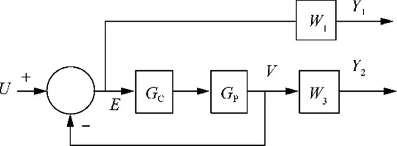
Fig. 13 Block diagram of H∞controller design.
Fig. 13 shows the block diagram used to set up a typical H∞controller. The weighting function W1is applied to the error signal, and if this signal is denoted as E, it is apparent that E=SU, where S=(I+GPGC)-1, which is commonly known as the sensitivity function. If the plant output is denoted as V, it is clear that W3weights the function V=TU, where T=(I+GPGC)-1GPGC, which is known as the complementary sensitivity function. The use of W1and W3is referred to as the mixed-sensitivity approach to H∞design. Once W1and W3are specified, the H∞design algorithm determines whether an internally stabilizing controller exists that satisfies the constraints that82(A) the frequencydependent singular values of the sensitivity function lie below the inverse of the W1weighting function and (B) the singular values of the complementary sensitivity function lie below the inverse of the W3weighting function.
Fig. 14 illustrates the block diagram for input to the H∞algorithm with prefeedback Kfin place.82The modified plant,consisting of the blocks GP,PID,-1,and Kf,was built in the z plane based on the 90° MIMO modal plant model and then converted to a w-plane realization, since the H∞design algorithms must be applied to continuous-time models. The term W1is a sixth-order weighting function comprised of identical second-order weightings applied to each of the three PCS loops. This weighting specifies 14 dB of sensitivity function attenuation in the w-plane frequency range of 0.001–0.1 Hz.The term W3, a third-order weighting comprised of identical first-order weightings applied to each plant output, specifies complementary sensitivity function attenuation at w plane frequencies above 100 Hz.
The design algorithms were used to obtain an 82nd-order H∞controller that meets the specifications. The design is successful in the sense that, under linear analysis and simulation,it stabilizes the MIMO modal plant model and provides improved disturbance attenuation over the SAGA-II controller implementation.82,83The disturbance rejection achieved with the H∞controller is superior to that of SAGA-II in all three vehicle axes.
3.4. Covariance control design algorithms
The Purdue University Covariance Control Design Algorithms55team, led by Robert E. Skelton, applied two variations of covariance control to the design of a UPS PCS. In the first,control energy is minimized subject to inequality constraints on the output covariance matrix. This is an Output Covariance Constraint (OCC) controller. In the second, using alternating projections, the same covariance constraints are imposed on the output, with an additional equality constraint on the controller covariance (a covariance (COV) controller,obtained from covariance control theory84). An advantage of the controller covariance constraint is that it allows for proper scaling of the controller for digital implementation in a control computer using fixed-point arithmetic,which is the case for the HST PCS.In the Purdue design approach,modal cost analysis is used to reduce the NASA-provided 118th-order model to a new ‘‘truth” model of an 83rd order and to develop a 32ndorder ‘‘design” model. Then, the OCC design algorithm is applied to design a full-order dynamic controller based on the reduced-order design model.The Alternating Convex Projection (ACP) algorithm is applied to find a feasible state covariance matrix satisfying all performance requirements.Using this covariance matrix, a covariance controller with a minimal control effort is constructed to satisfy the design objectives.15Finally, the finite-word length effects on the controller implementation are considered and evaluated. A workstation environment has been created in which these and other algorithms are used in an iterative procedure for identification,modeling, and control design.
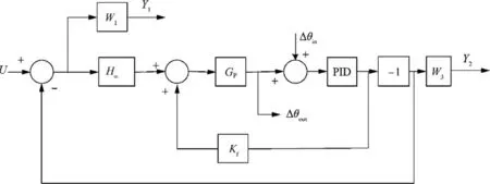
Fig. 14 H∞problem setup with prefeedback.82
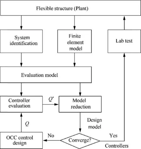
Fig. 15 Block diagram of integrated modeling and control.83
The main idea of the integrated modeling and control algorithm is shown in Fig.15.Note that in the integrated modeling and control iterative process,the modes that are important for control influence the modes selected in model reduction.Based on the given or identified model, this integrated process will produce controllers for evaluation.83The integrated modeling and control algorithm uses the OCC technique for controller design and the modal cost analysis technique for model reduction.
OCC controllers are designed by using reduced 34th-order models associated with solar array angles at 0°, 45°, and 105°. It turns out that the controller based on the reducedorder model associated with a solar panel angle at 0° provides the single best controller performance over the three evaluation models associated with solar array angles at 0°, 45°, and 105°. Hence, the OCC control design is based on the reduced-order design model of a solar panel angle at 0°.Covariance control theory provides a characterization of all assignable covariance matrices and, in addition, a parameterization of all controllers that assign a particular assignable covariance.
3.5. Dual-mode disturbance-accommodating controller
Developed by Johnson and Addington at the University of Alabama in Huntsville (UAH), dual-mode disturbanceaccommodating controller design56is particularly well suited for problems of this nature. The design team from UAH employed DAC to develop two strategies for coping with unexpected solar array disturbances, i.e., the Total Isolation(TI)and Array Damping(AD)strategies.56The DAC method is naturally applied to problems such as thermally induced structural vibration disturbances imparted on a UPS PCS by solar arrays. These disturbances have a distinguishable damped-oscillation-type waveform characteristic, which may have varying initial conditions but is generally smooth and well behaved. The DAC theory is based on the assumption that an unknown disturbance for which compensation is to be designed has this type of waveform behavior and is triggered only occasionally,as opposed to being erratic or random in nature. The planar model includes all the main body and solar array interface dynamics of the UPS.It was derived using the method of Kane’s equations85as implemented in a computer-aided modeling program. Although the model is a‘‘simple”planar model,the equations of motion for the system are quite complex. The details of the model development and the full equations of motion were presented in Ref.56. The TI and AD control strategies, briefly described below, were verified in a simulation based on the planar dynamic model. The HST masses, stiffness, inertias, and dimensions were used in the planar simulation employed to evaluate the controllers.Both the 0.11 and 0.65 Hz modes were simulated as in-plane modes. It should be pointed out that the 0.11 Hz mode is an out-of-plane mode. The technical details of the development of the TI and AD controllers and the composite observers that produce the state and disturbance-state estimates were presented in Ref.56.
The DAC controller proposed for the single-axis model is shown in Fig. 16.86The TI controller is an associated state observer, where parameters ξ, wnare assumed chosen to yield the desired quality of the closed-loop regulation response,where design parameters ξ, wncan be chosen to yield the desired ‘‘settling time” for the actively augmented damping of solar array oscillations.
In both the TI and AD modes of control, the presumed real-time plant output measurements for the planar-motion configuration of Fig.1686consist of the HST main-body pointing angle φ(t) only. In any consideration of a dual-mode controller, the question of how to gracefully ‘‘switch” from one mode to the other naturally arises. In principle, such mode switching is usually accomplished by a slow ‘‘fading” from one mode to the other, similar to the way one fades signals from right to left speakers in a stereo sound system.However,this fading procedure must be done in such a way that one control mode does not tend to‘‘fight”the other control mode during the fading/mixing process. In this study, it was found necessary to fade one control mode to zero before fading to the other control mode in order to avoid the fighting effect. The DAC pointing controller mentioned above can be adapted to a variety of similar space-based ‘‘pointing projects” where flex-body oscillations of attached appendages cause pointing‘‘disturbances”.86
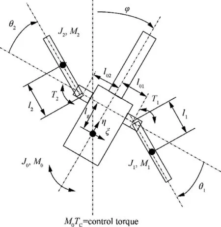
Fig. 16 Planar-motion (single-axis) configurational model and attached solar arrays.86
3.6. Parametric adaptive control techniques
In recent years, parametric adaptive control techniques87–90have been developed rapidly, especially parametric adaptive control of single-rod electrohydraulic, neural adaptive back stepping control of a robotic manipulator,and saturated adaptive control of electrohydraulic. They have been greatly promoted in robots and other fields, and have achieved remarkable results.
Different from the previous strict-feedback controllers used in a single-rod Electrohydraulic System (EHS), the proposed controller avoids the model order-reduction problem and relaxes the strict-feedback model assumption for the singlerod EHS encountered by existing results.87The effectiveness of the EHS is demonstrated by a comparison with the strictfeedback controller via both simulation and experiments. In Ref. 88, a neural adaptive control for a single-rod EHS improved the dynamic tracking performance of the cylinder position under these lumped uncertainties.Moreover,an adaptive estimation law was used to self-tune trained-node weights,and self-learning models were online optimized to enhance the robustness of the neural adaptive controller.An adaptive Neural Network (NN) controller of a two-degree-of-freedom manipulator driven by an electrohydraulic actuator was presented.89The effectiveness of the proposed controller was verified by comparative simulation and experimental results with proportional-integral-derivative and TBC methods.89
A saturated adaptive controller of an Electrohydraulic Actuator (EHA) was proposed to drive the joint motion of a two-degree-of-freedom robotic arm.90Parametric adaptive control techniques can quickly recover unsaturated dynamics with satisfactory tracking accuracy under largely unknown load disturbance and parametric uncertainty.87–90It is expected to be applied in solving the micro-vibration of 3U in the future.
4. Micro-vibration suppression techniques
The micro-vibration onboard usually refers to low-level mechanical vibration or disturbance in the space environment,typically occurring in a frequency range from lower than 1 Hz up to 1 kHz.1,11,21Therefore, there are many inducing factors of micro-vibration onboard spacecraft, such as high-speed rotation of rotating parts, step-by-step motion of driving mechanisms of large controllable components, and ignition of thrusters during orbit change and attitude adjustment.11Micro-vibration generated by a disturbance source can propagate in spacecraft structures for a very long time due to very tiny environmental damping in aerospace. Thus, it will affect the pointing performance of spacecraft, especially for UPSs.In general, three kinds of suppression technique can be classified for suppression of micro-vibration onboard spacecraft,i.e.,disturbance source control,transfer path control,and payload control. Micro-vibration suppression technology is currently a hot topic in the field of aerospace engineering. In this section, these three types of suppression techniques will be discussed, including suppression mechanisms and characteristics.
4.1. Disturbance source suppression approaches
In principle, vibration suppression methods can be divided into two categories: vibration reduction and vibration isolation.11,91,92The principle of vibration reduction is to use a damping device to consume the energy of vibration in a position where the structural strain energy is high. The damping device can be made of passive damping material or active piezoelectric ceramic material. Whilst the primary principle of vibration isolation is to disconnect the vibration transmission path from the vibration source to the sensitive equipment and install a vibration isolation device between the vibration source and the sensitive equipment to prevent the transmission of vibration. The vibration isolation device can be active, passive, or active–passive hybrid. However, the suppression of a micro-vibration source mainly includes two aspects93,94: (A)optimize the structure of the micro-vibration source to reduce the disturbance output from the vibration source as much as possible and (B) design vibration isolation for the vibration source.
It is pointed out in Ref. [95] that the performance of a disturbance source can be optimized by means of structural optimization design to reduce disturbance.Taking the disturbance output response at the interface between the disturbance source and the spacecraft as the optimization target has obvious theoretical and practical significance.96–98When the vibration along a certain degree of freedom is decoupled from other degrees of freedom,the energy of external disturbance work is only concentrated on that degree of freedom.99,100Hence, by decoupling the six-degree-of-freedom motion of a flywheel system, the complex vibration response of the system in the resonance region can be reduced,and the disturbance performance of the system can be improved.101,102In order to ensure a good performance of the flywheel system in six degrees of freedom,the distribution interval of each natural frequency should be minimized,which will make the natural frequency distribution of the disturbance source reasonable.103,104
The early damping device for spacecraft was mainly designed for the harsh dynamic environment during rocket launch.105,1A spacecraft micro-vibration suppression device is intended for long-term use in orbit, so its working environment is very different. The micro-vibration amplitude of the dynamic load is at the micrometer level, and it is also subject to special environmental conditions such as space radiation,vacuum, and high and low temperature alternation for a long time. Its design requirements are also different from those of previous damping devices. In general, the micro-vibration damping device of a spacecraft should at least meet the following requirements.11,106,107(A)The damper shall have high sensitivity and provide a high damping ratio at the micrometer level. (B) A movement gap should be avoided by either minimizing the use of or not using a motion pair.In a microgravity space environment, the gap position of the motion pair on the vibration suppression device is in a random state. The microvibration generated by the moving parts will cause the collision of the gap surfaces of the motion pair, resulting in the amplification of the response component. (C) The mechanical characteristics of the vibration suppression device cannot be changed obviously under the persistent micro alternating stress.Changes of mechanical properties will bring incalculable risks to space photoelectric equipment. (D) In the space environment, the vibration suppression device should have good mechanical and chemical stability. That is to say, the stiffness and damping cannot have obvious attenuation, cold welding,or release gas or dust under space radiation,high and low temperature, or vacuum environment.
4.2. Payload suppression approaches
Usually, payload isolation is realized through the installation of an isolator between the High-Performance Optical Payload(HPOP)and the platform of a spacecraft.Many vibration isolation methods have been designed to protect the HPOP from the impact of micro-vibration in the spacecraft. Typical isolation systems for space optical telescopes, referred to as VISS and SUITE, have been described in Refs.108,109.
In the structural design of a large spacecraft, the coupling of vibration isolation and the modal shape of a large flexible structure should also be considered,and the vibration isolation frequency should not be too low, generally higher than 1 Hz.Tacsat-2 adopted improved D-struts110to connect the optical load and the service cabin for vibration suppression.111,112The JWST isolated the whole optical payload,that is,the optical load and the spacecraft were separated by a vibration isolator, and the overall vibration isolation frequency reached 1 Hz. In this way, the influence of the spacecraft disturbance on the imaging quality of the optical load can be minimized.The vibration isolation system is composed of four rodshaped vibration isolators arranged in a crisscrossed manner.
Vibration isolators are made of graphite,and the surface is covered with constrained damping rubber.113Based on the sixlegged parallel mechanism, the Spacecraft Research and Design Center in the US developed an Ultra-Quiet Platform(UQP) for optical load isolation, which indirectly determines the attitude of the payload by controlling the length of the six legs.114The isolation frequency is above 10 Hz, the frequency characteristic of the vibration isolation device is close to the modal frequency of the satellite structure,115and the modes are coupled with each other. It is not appropriate to consider the satellite structure as a single rigid body. At this time,the flexibility characteristic of the satellite structure must be taken into account.116The design of vibration isolation should take the flexibility of the whole satellite into account,and a vibration isolation device should be avoided by staggering the close-frequency, increasing the damping, and using other methods. In Ref.117, vibration isolators used in spacecraft micro-vibration suppression technology in recent years were reviewed in detail.
4.3. Transfer path suppression approaches
An intelligent control strategy called the transfer path suppression method,which is also known as the change transfer function,11,1,118is employed in the micro-vibration suppression design of Integrated Optical Satellites (IOSs),11where selfoptimization can be carried out in the change transfer function method. When the output disturbance characteristics of a vibration source are certain, the vibration response of the HPOP mounting surface on a spacecraft is closely related to the dynamic characteristics of the spacecraft structure.The disturbance from the vibration source to the HPOP in the spacecraft can be effectively reduced by optimizing the dynamic characteristics of the vibration transmission path of the spacecraft structure. This is a novel suppression method developed for IOSs in recent years.119,120
The integrated design of an optical camera and a satellite platform will be a great convenience to the optimization of the mechanical environment of the whole satellite. In Refs.120,121, the mathematical model of the micro-vibration source of an IOS was established, and the influence of the micro-vibration of the flywheel on the MTF of the HPOP was analyzed by the integrated modeling method. The microvibration environment of the IOS is more sensitive, but it is also relatively easy to study.121It can be used to establish an influence analysis model of micro-vibration on the HPOP from the disturbance source to the transfer path to the payload, as well as to allocate the index of micro-vibration suppression.11,122This is a novel method of micro-vibration suppression.
Usually, the cost of determining an optimal design to suppress the micro-vibration transfer path is high, as it involves the whole spacecraft structure dynamics. It makes the whole dynamic performance change, which may bring unnecessary trouble to the attitude control system. However, at the beginning of the whole satellite design, the micro-vibration characteristics of the whole platform are analyzed, and effective structural strengthening or restraining measures are taken.The cooperative design of the structural and control subsystems in the early stage may achieve amazing results.11,110,123
5. Disturbance-free payload satellite
At present, most of the high-performance spacecraft124use coarse and fine composite control plus passive vibration isolation to achieve precise PC and vibration suppression.125In the design process,it is necessary to fully consider the influences of system structural modes, sensor noise, and various micro vibration environments,126comprehensively design the controller bandwidth and structural dynamic characteristic parameters, carry out multiple iterative optimizations, and establish ultra-requirements for structure design and disturbance sources.For the limited isolation performance of a passive vibration isolator, there is nothing to do with lowfrequency vibration and even amplification.127
A novel spacecraft architecture, known as Disturbance-Free Payload (DFP),128has been presented and successfully demonstrated experimentally.The DFP concept has significant performance improvement over other vibration isolation systems and awaits a space-based demonstration to reflect its true capabilities.129The payload and the spacecraft are separate bodies that fly in close proximity formation and interact through non-contact sensors and actuators to achieve precision payload control and isolation from spacecraft disturbances. Vibration isolation is provided down to zero frequency, and isolation performance is not limited by sensor characteristics. In this section, (A) the DFP concept and control architectures that are applicable to experimental demonstration are reviewed, (B) the experimental apparatus and relevant sensors and actuators are described, and (C) experimental results of broadband transmissibility are presented.These demonstrate the significant performance benefits resulting from the use of the DFP architecture.
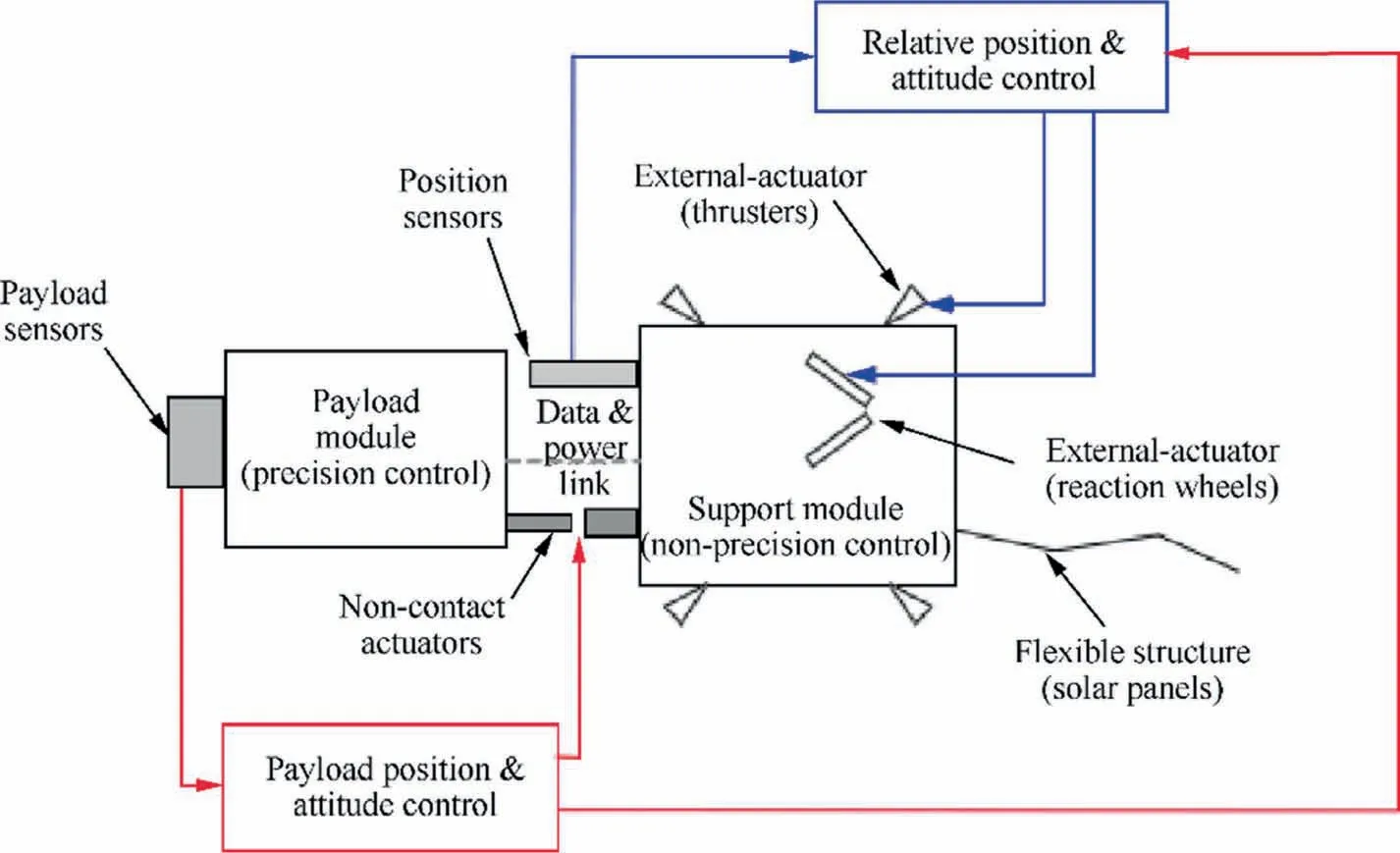
Fig. 17 Spacecraft DFP Architecture.130
5.1. DFP concept and control architecture
Fig. 17130shows a DFP system that includes a Payload Module (PM) and a Support Module (SM) that are mechanically de-coupled. The motion of the PM is controlled by reacting on the SM using non-contact actuators located between the two modules. The motion of the SM is controlled to follow the PM using external actuators that react against the surroundings. In the pure DFP concept, no force is applied between the payload and support modules to achieve relative motion control.
Fig. 18130describes a top-level block diagram of the DFP control system as it applies to an experimental demonstration.In this variation of the DFP control architecture, non-contact actuators are used for relative translation control,and external actuators are used for relative attitude control between the payload and support modules. The forces on the non-contact actuators for relative translation control are computed to generate zero moment about the center of mass of the PM and therefore do not affect the attitude of the PM.
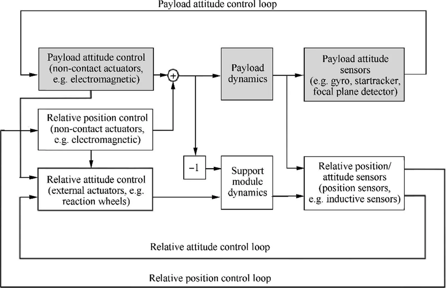
Fig. 18 DFP control architecture with non-contact actuators.130
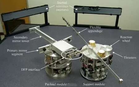
Fig. 19 DFP Testbed.130
The architecture shown in Fig. 18 contains three control loops: (A) payload attitude control, (B) relative attitude control,and(C)relative position control.Payload attitude control affects controls of both relative attitude and translation, while relative attitude control does not affect payload attitude control.All control loops are PID control with bandwidths appropriately selected to provide gain stabilization.This architecture provides near-zero transmissibility from SM disturbances to payload attitude at all frequencies.
5.2. Experimental apparatus
Fig.19,130shows a view of the test apparatus,which is referred to as the DFP testbed.A granite table is used as a flotation surface and provides an operational area of 3.7 m×2.3 m. The vehicle consists of a PM and an SM that interact through the DFP interface. There is no mechanical link between the PM and the SM, and except for air bearings, there is no mechanical link between the vehicle and the ground.The vehicle is equipped with sensors and actuators to implement the control logic and assess the performance. A ground station is used to send asynchronous commands to the vehicle and receive data from various vehicle sensors, which are displayed in real-time and stored for post-processing and performance analysis. The two large mirrors shown in the figure provide an inertial reference for the fine optical pointing system.
Table 1129summarizes the performance assessment sensors and the approximate noise floor, which was determined through independent tests. The noise floor, in particular, is of importance because it shows the limitations of the sensors and gives an indication where performance measurements are limited by a low Signal-to-Noise Ratio (SNR).

Table 1 DFP Performance Sensor Characteristics.129
5.3. Experimental results
The autonomous vehicle consists of two separate bodies, the payload and support modules,PM and SM respectively. Each contains a complete set of subsystems required for operation and performance assessment. The vehicle structure is designed to accommodate engineering support equipment and have dynamics representative of a large space telescope, such as the JWST. The PM contains structures that represent the petals of a segmented mirror and the tower of a secondary mirror assembly. These are mounted to the hub through flexures tuned to achieve a desired first mode resonant frequency for each element. The SM has a long flexible appendage that represents the structural dynamics of a large sunshield.The boom holding sensors and actuators at the DFP interface is also designed to have a first bending mode frequency that is representative of an actual spacecraft design.In addition,mass and inertia ratios of the PM and the SM are representative of a large space telescope.
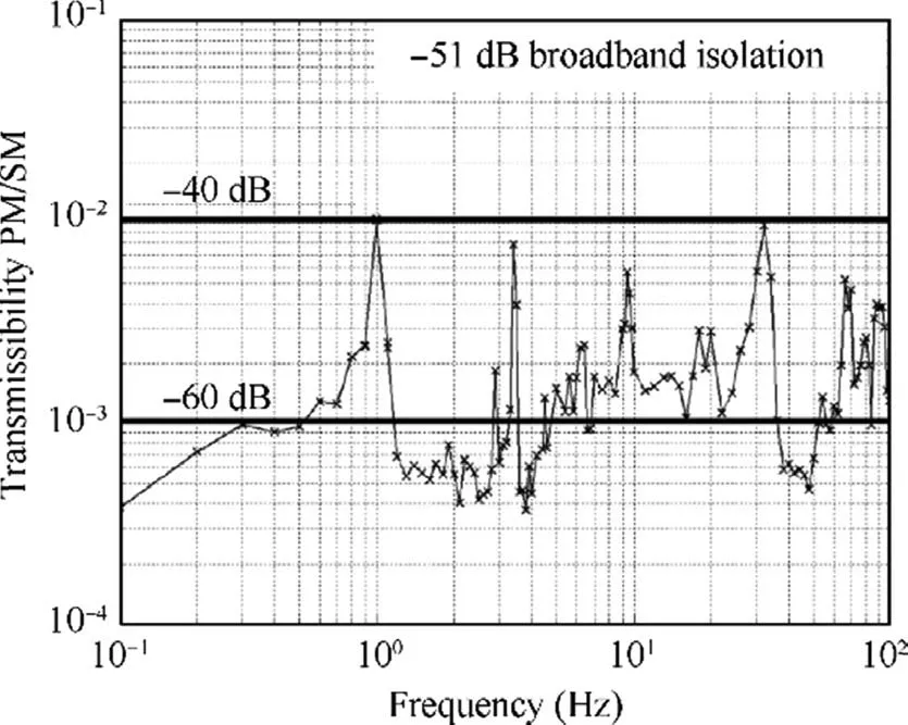
Fig. 20 Block diagram of DFP vibration isolation131,132.
In a ground air-flotation platform test, the DFP approach achieved the active vibration isolation effect of -51 dB in the whole frequency band as shown in Fig. 20.131,132
By DFP technology,the vibration level of the loading cabin can be 2–4 orders of magnitude lower than the task demand of 0.1′′.Simulation results show that the pointing accuracies of X(roll) and Y (pitch) directions are 0.003 2′′and 0.003 4′′,respectively.
6. Conclusions
According to the development of ultra-performance spacecraft pointing control methods, technical indicators of ultra-pointing control are generally required to reach the milli-arc-second level, and there will be more stringent requirements in the future. With the continuous improvement of technical indicators, some new methods and ideas are needed on the basis of traditional design methods of PCSs.
A commonly used ultra-precision pointing control method generally adopts the multi-level compound axis control method, uses an FGS as the sensor, and needs special treatment methods for various disturbance sources, microvibration sources, and sensitive loads that affect the pointing accuracy. In order to reduce the impacts of medium- and high-frequency disturbances, in addition to passive vibration reduction and isolation,active pointing hexapod vibration isolation platform technology with vibration isolation and pointing adjustment function is an important development topic.However, for the limited isolation performance of a passive vibration isolator, there is nothing to do with low-frequency(~0.1 Hz)vibration and even amplification. The measurement accuracy of a 0.001′′sensor is the primaries for further improvement of PCSs. Ultra-high-performance sensors are seriously desirable in the future.
Noticeably, some advanced controllers and/or algorithms such as ROM-based DAC and ROM/RMF controllers,LQG-based controllers, H∞controllers, OCC and COV controllers, TI and AD controllers and/or algorithms have been developed for vibration suppression of low frequency, which have excellent performance and reliability and could be of great potential in the area. ROM-based DAC and ROM/RMF techniques produced very promising results in linear simulation with pointing errors well below the prescribed requirements. The tracking properties of an LQG controller are improved over those of the original PID controller.Improvement in performance in terms of peak and rms attitude errors has been seen in using H∞constraints to improve the controller stability characteristics and performance. The dramatic improvement of OCC and COV controller performances that these control techniques manifest is in control energy. A TI controller is very effective in maintaining pointing stability in the face of the disturbance torques imparted by vibrating solar arrays. Parametric adaptive control techniques, such as parametric adaptive control of single-rod electrohydraulic, neural adaptive back stepping control of a robotic manipulator,and saturated adaptive control of electrohydraulic, have been greatly promoted in robots and other fields, and have achieved remarkable results, which are expected to be applied in solving the micro-vibration of 3U in the future.
Recall that micro-vibration techniques were required to develop a 3U spacecraft. Before the suppression of a microvibration source, it is necessary to study the characteristics of the micro-vibration source.Hence,it is necessary to analyze and/or test the mechanism of the disturbance of each disturbance source to obtain the vibration amplitude and the spectrum of micro-vibration, which can be the first step for the design of micro-vibration suppression, the determination of vibration reduction performance, and the evaluation of the impact on the 3U spacecraft.Usually,the transfer path control method mainly concentrates on the whole satellite structure.This approach is effective but limited to an integrated design of an optical camera and a satellite platform. Payload control is realized through the installation of an isolator between the HPOP and the spacecraft bus.Some advanced nonlinear isolation methods such as nonlinear damping and nonlinear stiffness techniques have been developed for vibration isolation of low frequency and/or in a wide frequency range,which have excellent isolation performance and reliability.Nonlinear stiffness isolation systems can be used by combining with nonlinear damping systems to achieve an advantageous vibration isolation performance with only pure passive components,and thus could be of a much greater significance to the general field of vibration isolation/suppression/control.
A proposed DFP control architecture overcomes the inherent limitations of existing pointing control and isolation systems, providing a system that is robust and largely insensitive to disturbances and dynamics of a spacecraft and sunshield, reducing risks both in orbit and for ground testing that is not limited by sensor characteristics. This also allows reductions in cost and schedule due to reduced and simplified ground testing and characterization. The large performance margins provided by a DFP translate into relaxed requirements for a spacecraft and several components, resulting in a reduction in cost. For example, requirements on reaction wheel balancing are greatly reduced, leading to a lower cost.The DFP concept is applicable to a broad range of space missions with stringent control and motion stability requirements.It has far reached implications beyond improved performance,such as relaxed spacecraft requirements, simplified on-orbit operations, and reduced requirements for ground testing and characterization. These translate into reduced risk and cost and enable current and future precision space systems.
Declaration of Competing Interest
The authors declare that they have no known competing financial interests or personal relationships that could have appeared to influence the work reported in this paper.
Acknowledgement
The authors gratefully acknowledge the support from the National Natural Science Foundation of China (No.51905034).
 CHINESE JOURNAL OF AERONAUTICS2021年10期
- CHINESE JOURNAL OF AERONAUTICS的其它文章
- Direct dynamic-simulation approach to trajectory optimization
- A strong robustness open-circuit fault diagnosis strategy for novel fault-tolerant electric drive system based on d-q-axis current signal
- Nonlinear vibration response characteristics of a dual-rotor-bearing system with squeeze film damper
- Ground maneuver for front-wheel drive aircraft via deep reinforcement learning
- Numerical simulation of a UAV impacting engine fan blades
- Transition characteristics for a small tail-sitter unmanned aerial vehicle
