Transition characteristics for a small tail-sitter unmanned aerial vehicle
Jingyang ZHONG, Chen WANG
School of Construction Machinery, Chang’an University, Xi’an 710061, China
KEYWORDS Actuator dynamics;Tail-sitter;Time delay;Transition analysis;UAV
Abstract Research on the transition phase of tail-sitter Unmanned Aerial Vehicles(UAVs)is crucial for trajectory planning and performance analysis.This study focuses on the analysis of the transition characteristics and path of a small dual-rotor tail-sitter UAV, including static and dynamic computations. The system input time delay and actuator dynamics are specifically considered during the dynamic analysis, and these actual physical properties ensure that the computation results are reliable and reasonable.The UAV steady-state limit is obtained through static analysis,which is also adopted to verify the correctness of the dynamic results.In regard to the dynamic analysis,several typical transition approaches are computed based on different initial states and optimization objective functions, and the different computations are applicable under specific task conditions.The off-line dynamic results of the transition path and actuator output sequence could also be adopted as reference values for the transition process during real flight. A comparison of the static and dynamic results illustrates the necessity of combining these two methods for UAV transition characteristic analysis.Furthermore,the UAV conceptual parameters related to the transition path are also studied, and the obtained quantitative characteristics provide feedback for the UAV conceptual design.
1. Introduction
With the development of sensor miniaturization and unmanned techniques, small Unmanned Aerial Vehicles(UAVs) have aroused worldwide concern and have been researched by many scholars and experts. The UAV exhibits a great potential in both civil and military fields,1–3such as freight transport, forest rescue and coordinated strikes.Fixed-wing and rotor-wing vehicles are the two most commonly implemented UAVs and they handle tasks consistent with their advantages. However, the dependence of the fixedwing UAV on a runway and the low forward-flight efficiency of the rotor-wing UAV limits their application to a certain extent. To resolve the above problems, three types of Vertical Takeoff and Landing (VTOL) vehicles have been proposed,including tilt-wing4or tilt-rotor vehicles,5hybrid fixed-wing vehicles6and tail-sitter vehicles.7Compared to conventional aircraft, VTOL vehicles can both hover and rapidly fly forward,and this advantage has encouraged researchers to invest much effort in this field.
To accomplish the above transition during flight, the tiltrotor or tilt-wing UAV tilts its wing or rotors to change the thrust direction, and the coordinate system of the body remains the same during both hovering and forwarding flight.8The hybrid fixed-wing UAV contains two propulsion systems,namely, four rotors are employed while hovering, and a propulsion rotor is used during forwarding flight. The coordinate system of the body of this UAV does not change. However, these two types of UAVs have high weight due to the components needed to accomplish the transition, such as the transition mechanism or two power systems. The tail-sitter UAV does not require a complicated transition mechanism,which avoids transition failure due to mechanism malfunctions. During transition, the tail-sitter UAV adjusts the body direction by approximately 90°, which leads to a change in its coordinate system.9As a result, the tail-sitter UAV may encounter a large angle of attack, major altitude climbing or control deficiency during the transition process; however, this phase is crucial to accomplish the tasks. Therefore, it is necessary to analyze the relevant transition characteristics in detail.The transition process can be divided into two main phases,i.e.,forward transition(hovering to level flight)and backward transition (level flight to hovering).
In the earlier studies of tail-sitter UAV transition fight,most researchers focused on force and moment trimming,which could be regarded as static analysis.Itasse et al.10investigated the static transition characteristics of a dual-rotor tailsitter UAV.Based on the longitudinal force and moment trimming equation, the trimming states of the flight speed versus the angle of attack,the motor speed versus the angle of attack,and the deflection of elevator versus the angle of attack were obtained during the transition process.Furthermore,the sensitivity of the lift,drag,and pitch moments in regard to the UAV status and control quantity were calculated near the equilibrium point based on the small-perturbance theory. Kubo and Suzuki11examined the effects of the trailing-edge flap and leading-edge slat of a coaxial rotor tail-sitter UAV on the trimming state during the transition process. Their computation results revealed that the trailing-edge flaps only slightly affected the improvement of the stall characteristics during the transition. In contrast, the leading-edge slats greatly enhanced the stall characteristics.
Other researchers attempted to determine the optimal transition path of the tail-sitter UAV during the transition process.The UAV dynamic differential equation is often applied to these solution processes. The computation results depend on the time which could reflect the transition process in the time domain, and thus, the above could be regarded as dynamic analysis. Wang et al.12,13implemented a dynamic programming method to calculate the optimal forward transition trajectory. Discretization of the UAV’s nonlinear system was first realized, and the optimal solution was based on the discretized system. Although an optimized trajectory was obtained, the setting of the optimal goal only considered whether the UAV could complete the transition, and the time and space restriction during the transition process were not considered in his study. However, the UAV states during the transition were determined. To improve the altitude change during backward transition, Verling et al.14added the altitude change to the cost function during transition analysis of the Wingtra S100 tail-sitter UAV.The optimal strategy was based on fixed initial and final times. The desired pitch angle and throttle variation that the UAV should follow during the transition process were calculated. The altitude change improvements were verified through simulation and flight tests.However, only one initial state of the UAV was considered and calculated, and the transition completion time was assumed beforehand. Additionally, the disturbance problems were not analyzed. Li et al.15investigated the optimal transition problem of a quadrotor tail-sitter UAV,and the main task of this work was to suppress altitude variations under a limited transition time during the transition process.Compared to the traditional linear transition methods,the optimal results could enable the vehicle to finish a transition in less time and with less altitude change. Oosedo et al.16,17investigated the minimum-time and minimum-altitude change strategy of a quad-rotor tail-sitter UAV during the transition process. The variables to be optimized included the throttle variations and pitch angle. Simulation and flight tests verified that the optimized results facilitated the altitude change over the results before optimization. However, the actuator dynamics, time delay of the system input, and moment of inertia of the UAV, which are all related to the actual UAV characteristics,were not considered,and only the forward transition was studied. Naldi and Marconi18studied the optimal transition maneuvers for a tail-sitter UAV considering both minimumtime and minimum-energy constraints. The numerical trajectory computation results show the effectiveness of the proposed methodology in dealing with the UAV’s system.Maqsood and Go19–24researched the transition characteristics of a UAV with inner-part wings that exhibited a variable angle of attack. In his study, the transition completion time was set beforehand. The variables to be optimized included the angle of attack of the inner-part wings,deflection of the control surface, and the throttle. Compared to the traditional tail-sitter UAV whose wing cannot be rotated along the y axis of the body,the design of a variable angle of attack greatly decreased the altitude change during the forward transition process.Additionally, this design reduced the dependence of the UAV on the thrust-weight ratio during the transition process.Banazadeh et al.25,26also analyzed the transition characteristics of a tail-sitter UAV with a jet engine. Their computation results reveled that the lowest thrust-weight ratio required for altitude maintenance during the transition process for this particular UAV should be higher than 1.1. A high thrustweight ratio yielded a short transition time and low altitude change. Additionally, the tail-sitter UAV transition control problems have also been studied by different researchers. Liu et al.27designed a robust hierarchical controller to achieve aggressive flight mode transitions. The theoretical analysis and numerical simulation results showed the effectiveness of the proposed control method. Li et al.9considered the couplings, which are high nonlinear and strong, to be a challenging problem for transition control design. A H-infinity controller and a nonlinear disturbance are combined to solve this problem. Raj et al.28proposed a solution to the attitude tracking problem for a novel quadrotor tail-sitter UAV and the controller was uniformly valid for all attitudes and is based on dynamic feedback linearization in a geometric control framework. Other researchers29,30also performed research on the transition control fields.
From the above studies,it is found that although static and dynamic analysis work has been performed in regard to the transition process of the tail-sitter UAV, further investigation is still required. In terms of static analysis, although trimming analysis has been conducted, as in Ref.10and Ref.11, few researchers considered the different aerodynamic effects on the various wing parts and control surfaces due to the propeller slipstream. The propeller slipstream divides the wing and control surfaces into different areas within and outside the slipstream, respectively. The propeller slipstream also affects the angle of attack and dynamic pressure on the different sections of the wing and control surfaces.These characteristics are crucial for the tail-sitter UAV. However, they have often been ignored by researchers. In regard to dynamic analysis,as reported by Oosedo et al.16,the time delay and dynamics were not considered,and the time delay and dynamics have also been largely overlooked by other researchers. However,these characteristics occur in real systems and the analysis results are less reliable when these characteristics are not considered. Moreover, most researchers have only attempted to determine the optimal transition trajectory.
The main contributions of this study are as follows: First,the effects of the propeller slipstream on the different wing and control surface areas and the corresponding effects on the angle of attack and dynamic pressure are considered during the static analysis modeling process. Second, most researchers have only studied separate transition characteristics based on either static or dynamic analysis, while mutual confirmation by these two methods is lacking, which is addressed in this study. Third, the system input time delay and actuator dynamics are evaluated during dynamic analysis,which has not been the research focus of most researchers.Finally, most researchers have only focused on determining a specific transition trajectory under a particular optimization goal, and the studies investigating different possible transition trajectories are insufficient. However, various flight missions may demand distinct transition trajectories. Therefore, this study more completely analyzes and considers additional aircraft characteristics given the problems mentioned above.
The rest of this paper is organized as follows.Section 2 presents the problem description and static analysis of the UAV’s transition characteristics. Section 3 proposes the detailed dynamic analysis process and especially considers the impact of the system’s input time delay and actuator’s dynamics.The transition paths are calculated under different initial states and different objective functions corresponding to different working conditions. The impacts of the UAV’s conceptual parameter to the transition path and a comparison of the static and dynamic analyses are also discussed. Finally, some concluding remarks are drawn in Section 4.
2. Static analysis of transition characteristics
2.1. Problem description and modeling
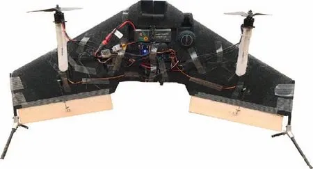
Fig. 1 Prototype of UAV.
For the tail-sitter UAV31considered in this study, as shown in Fig.1,the transition flight is driven by control surfaces whose efficiencies are mainly influenced by the propeller slipstream.During hovering, two propellers are employed to generate lift to compensate for the UAV gravity, and the differential thrusts of these two propellers provide the control moment in one degree of freedom. The symmetrical and asymmetrical deflection of the control surfaces are used for generating the control moments in the other two degrees of freedom. During level flight,the control logic is similar to that during hovering.The transition is driven by the cooperation between the thrust and pitch moment generated by the propellers and control surfaces,respectively.Due to the effects of the propeller,the wing and the control surfaces are largely divided into two parts,which are the areas within and outside the slipstream section.These different areas experience distinct dynamic pressures and angles of attack, and it is necessary to consider these features when modeling the tail-sitter UAV in this study.
Considering that the transition process mainly occurs in the x-z plane, the computation and analysis are performed based on dynamic and kinematic equations considering three degrees of freedom. The force conditions, angles of attack and airspeeds in the different areas are shown in Fig.2.Certain notations are defined as follows: xband zbare the body coordinates; xeand zeare the inertial coordinates; ain, Vin,Linand Dinare the angle of attack, airspeed, lift and drag respectively, within the propeller slipstream; aout, Vout, Loutand Doutare the angle of attack,airspeed,lift and drag respectively, outside the propeller slipstream; θ is the UAV pitch angle;G is the UAV gravity;M represents the moments acting on the UAV center of gravity;T1and T2denote the thrust generated by the two motors.
The UAV dynamic and kinematic equations for the transition characteristics analysis are described as follows. To make the definition of aerodynamics and angle of attack easier to grasp, the following aerodynamics related and angle of attack related definitions are consistent with the conventional fixed wing coordinate.

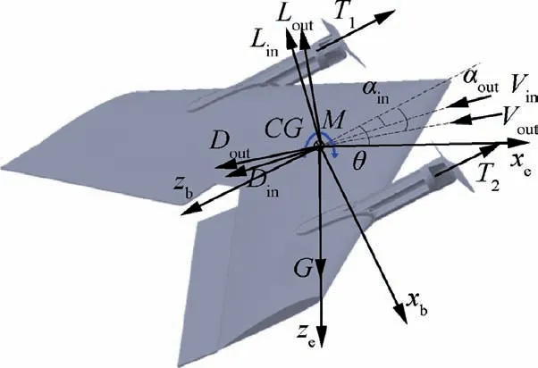
Fig. 2 Force condition of UAV.
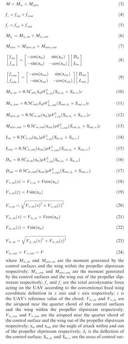
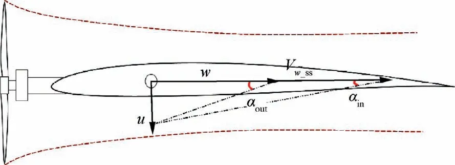
Fig. 3 Angle of attack within and out of propeller slipstream.

Table 1 UAV’s conceptual parameters.
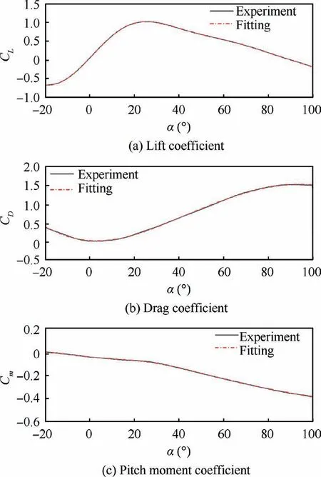
Fig. 4 Aerodynamic coefficient fitting.
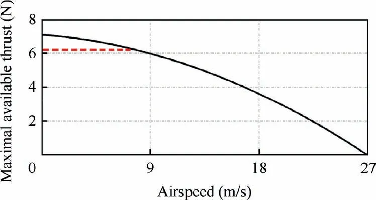
Fig. 5 Relationship between maximal available thrust and airspeed.
The rest of the parameters, including the dynamic parameters and the UAV’s conceptual parameters, are obtained from numerical computation and experiments, respectively, from our previous studies.33
Furthermore, the propellers considered in this study are fixed-pitch propellers,and the thrust decreases with increasing airspeed. With the use of data acquired from the APC website34, the relationship between the maximal available thrust and airspeed is obtained, as indicated by the black line shown in Fig. 5.
The maximal available thrust based on the acquired APC data is approximately 7.1 N. However, based on our previous study,the maximal thrust offered by this propeller amounts to 6.25 N,and in the following analysis,the maximal thrust value is restricted to 6.25 N as indicated by the dashed line.
2.2. Problem analysis and solving method
From Eqs. (1)–(24), it is found that there are five variables to be determined. However, only three trimming equations (Eqs.(1)–(3))are applicable.These five variables include the angle of attack(a),deflection of the control surface(δe),thrust(T),airspeed (V) and pitch angle (θ) and there are seemingly infinite solutions for these indeterminate equations. However, considering that the object to be analyzed is the tail-sitter UAV,which has an actual physical meaning, and many variables,thus, have boundaries due to physical constraints. Moreover,only limited ranges of the above variables are of interest,and finite solutions can be obtained under these constraints.In each solution process, the airspeed and pitch angle are set beforehand, and the remaining three variables can then be resolved.
The genetic algorithm suitably handles nonlinear problems and does not require initial values that are close to the final values. These characteristics make the genetic algorithm an appropriate choice to resolve this problem.
The objective function can be set as

The reason of this objective function setting is as follows.From Eqs. (1)–(3), it can be known that Fx, Fzrepresent the total force acting on the UAV, and M represents the total moment acting on the UAV. The objective function J is the quadratic sum of the above three variables. Therefore, the numerical values of J can be used to decide if the trimming point can be achieved.If the solution of the objective function is smaller than a certain threshold, such as 10-6, we can then regard this solution as the UAV trimming condition at the specified airspeed and pitch angle. Because the small values of J mean that Fx, Fz, and M are all small enough, which denotes that the force and moment are trimmed.If the solution of the objective function is larger than a certain value such as 0.1, the solution is then regarded as nonapplicable. Considering the random characteristics of the initial values required by the genetic algorithm, the solution of each computation may not remain the same, and at most fifteen operations are executed to mitigate this effect.These fifteen operations represent the tradeoff between the computation time and result reliability. During early trial computations considering different initial speeds and pitch angles, fifteen computations were verified to be reliable. If the solution falls between the two values mentioned above,further calculations are then needed because the genetic algorithm’s initial values are random. The computation results obtained with the genetic algorithm are then adopted as the initial values of the Newton iteration algorithm for the further calculation.The results obtained with the Newton iteration algorithm are verified with Eqs.(1)–(3).This solution process is shown in Fig. 6.
2.3. Solution parameters and results
In this section,the parameters of the genetic algorithm and the boundaries of the variables are defined. The relevant parameters of the genetic algorithm applied in the computations are summarized in Table 2.

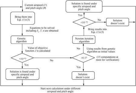
Fig. 6 Solution process.

Table 2 Genetic algorithm parameter setting.
The boundaries of the three independent variables, i.e., the deflection of the control surfaces (δe), angle of attack outside the propeller slipstream (aout), and thrust (T), are defined as

The scopes of the airspeed and the pitch angle in this study are set as V ∊[0;26] m/s and θ ∊[-100°;10°].
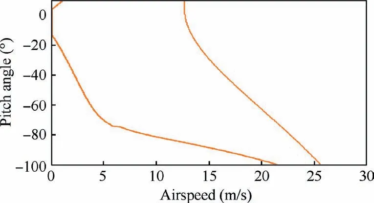
Fig. 7 Static relationship between pitch angle and airspeed.
The computation results are shown in Fig. 7. To obtain a smooth curve, the airspeed and pitch angle are divided into 300 different sections, and the total amount calculation is 300×300=90000. The range of V and θ for computation would initially span a rectangle.However,not all points in this rectangle exhibit the corresponding trimming conditions; the computation results are shown in Fig.7.The UAV could trim along or within the orange line boundary, as shown in Fig. 7 which reflects the static boundary during the transition. The maximal climbing speed is lower than 13 m/s at the hover stage when the UAV pitch angle is approximately 0°. Although the maximal speed during forward flight reaches approximately 26 m/s, it is observed that the pitch angle at this speed is negative. Based on the relationship between the propeller thrust and flight speed, as shown in Fig. 5, it is determined that the available thrust at the above airspeed almost reaches 0, and the UAV has to dive at a small angle to reach this flight speed with the help of the gravity component.The UAV steady-state limit is determined based on the results depicted in Fig.7,and these results are also adopted as reference values to decide whether the subsequent dynamic analysis results are reasonable. Although the steady-state limit is be calculated through static analysis, the UAV transition process is actually a dynamic process, but time-dependent states cannot be obtained. Therefore, dynamic analysis is needed and is described in the next section.
3. Dynamic analysis of transition characteristics
3.1. Problem description
In this section, the UAV transition characteristics are computed based on longitudinal flight dynamics.The computation process not only includes Eqs. (1)–(28) but also considers the following longitudinal dynamic and kinematic equation in the analysis.
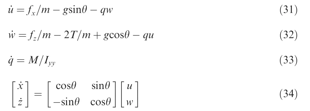
where u and w are the UAV’s linear velocity in the body frame;x and z are the UAV’s position in the inertial frame; Iyyis the moment of inertia in the y axis; q is the UAV’s pitch angular rate.
Considering that many different transition paths are possible,to ensure that the analysis results are meaningful,the transition time is regarded as the central factor in the following analysis process. By adopting the transition time as the optimization objective, the UAV attempts to complete the transition process as rapidly as possible, and the test result reflects the limit of the UAV’s ability to a certain extent. Moreover,the final pitch angle and flight speed are essential to confirm whether the transition process has been accomplished.
The transition process can be mainly divided into the following two stages: forward transition and backward transition. The possible transition strategies considering the particular working conditions are analyzed at these two stages first.
In regard to the forward transition stage, if the minimal time consumption is the only factor considered in the transition process,a drop in altitude may then occur during the transition process. The reason is that an overly rapid transition may change the UAV’s thrust line too fast, and the initial low flight speed may not generate enough lift to counteract the UAV gravity.This strategy would involve the fastest transition for a quick response, but the most severe altitude loss would occur. However, with the help of the boundary constraints of the UAV state, this transition can be guaranteed to be completed safely. If the altitude change constraint is added to the optimization objective, a relatively gentle transition could then be accomplished,which could be used as a general transition strategy. Furthermore, if a high final altitude is set under the minimum time objective, the fastest-climbing condition could also be obtained, and this transition is appropriate for specific terrains.In this study,the diving form at the forward transition stage is not specifically considered because this transition form may not be safe.
Likewise, the diving form during the backward transition process is not computed either due to safety considerations.The UAV usually climbs during the backward transition process because of the initial flight speed. Three different transition objectives are computed. The first strategy could be treated as a benchmark that only ensures that the UAV accomplishes the transition process without other goals added. The second strategy adds the altitude variation restriction to the optimization objective, which could be suitable for spacelimited conditions. The third strategy considers the time constraint to ensure that the transition process is finished as quickly as possible.
3.2. Transition analysis
The problem to be solved can be treated as a multi-objective optimization problem based on the analysis above, and this problem can be transformed into a single-objective optimization problem using weight coefficients for the different subobjective functions as follows:

where X(U) is the state of the UAV, which is related to the variable to be optimized; Gj(X(U)) is the jth nonlinear constraints;lb and ub are the lower and upper bounds of the variable to be optimized.
During the solution process, the UAV initial and final states are defined in advance,which represent the states before and after the transition, respectively. Considering that the transition time is not known beforehand, the transition time is also set as the variable to be optimized. Therefore, the UAV states are related to time and the variables to be optimized are δe0,T0,δe1,T1,...,δen,Tnand tf,which indicates that the deflections of the control surfaces in n time spans, the thrust input in n time spans and the transition completion time must be optimized for a total of 2n+1 variables,where n is a given parameter that reflects the number of times to be divided.
The objective function can be defined as

where W1is the state’s weight of the diagonal matrix;Xfis the final state after transition; tfis the transition finish time; Wtis the time’s weight.
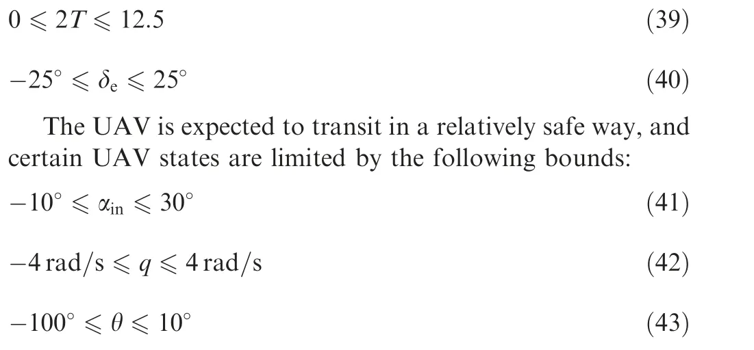
Furthermore, the optimization process is limited by the UAV physical constraints, and the variable boundaries to be optimized are as follows:
Considering that the constraints in this study are inequality constraints, the interior point method is used. The constraints are dealt with by adding the penalty item to the cost function as follows:

where τ>0 is a penalty factor;J is the original objective function;H~(x)is a barrier function.The barrier function is defined as

Fig. 8 Comparison of different conductions in regard to actuators.

This barrier function can guarantee that when X is close to the border, at least one of the Gj(X) approaches zero, which could lead the barrier function to infinity. This character can guarantee that the constraint boundaries cannot be reached.Furthermore, whether the constraints are violated or not also depends on the choice of the objective function,constraint settings and the problems to be studied.The settings of the objective function and constraints in this study are based on the considerations of the real UAV system,and no constraint violations occur in our study.
3.3. Consideration of system input time delay and actuator dynamics
The data flow from the sensors to the actuators’ output is not instantaneously accomplished in the real system.Discrete data sampling,data fusion dynamics or the dead zone and actuator dynamics can all introduce a time delay and certain dynamics to the system.If these factors are not considered,the actuators’commands are the same as how they are actually executed.The consideration of these factors implies that certain dynamics occur from the actuators’commands to their actual execution.The differences between these two conditions are shown in Fig. 8.
According to the previous studies, the input time delay of this system is approximately 25 ms. The time delay consideration complicates the optimization process, and the Pade approximation transforms a continuous time delay into an nth-order approximation via the transfer function form.Therefore,the MATLAB function Pade is first applied.Transfer functions of different orders are tested, and the results of the first- and third-order transfer functions are listed below.

However, when the input is a step function, the Pade approximation always produces an undesired response as shown in Fig. 9.
Regardless of the orders of the Pade approximation function, a step input always generates a reversed overshoot in response. These characteristics are undesirable in this study and disagree with the actual situation. Therefore, two new first-order dynamic functions are adopted instead to mitigate the effects of the combination of the time delay and actuator dynamics in this study. The motor and control surfacerelated bandwidths are defined as 15 and 25 rad/s,respectively.The step response between the original and equivalent systems is shown in Fig. 10.
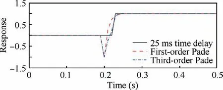
Fig. 9 Pade approximation of time delay.
3.4. Solution process and parameter setting
A flowchart of the solution process is shown in Fig. 11,where δe0(ini), T0(ini), δe1(ini), T1(ini), ... , δen(ini), Tn(ini)and tf0are the initial values of the variables to be optimized. Although the genetic algorithm suitably handles nonlinear problems, in this study,jagged results always occur even after several parameter setting attempts. These jagged results demonstrate that the deflection of control surfaces and thrust always fluctuate at an unacceptable level, which is unreasonable in a real UAV flight. Therefore, the gradient descent algorithm is finally adopted to solve this problem.
According to the 2n+1 initial values of the variables to be optimized and the initial states [u0, w0, q0, x0, z0, θ0], the state values in n time intervals, which involve 6×n matrices, are obtained based on aerodynamic,dynamic and kinematic models.Then,the results are substituted into the objective function to be solved with the gradient descent algorithm. The application of the actuator dynamics is shown in Fig. 12.
In Fig.12,BW is the equivalent actuator bandwidth value,which is given in Section 3.3;Ntis the number of the time interval of Tsto be divided and this number should not be too small in case of numerical divergence.
Nonlinear constraints are implemented,as shown in Fig.13.
During the solution process, the state in each time interval should satisfy Eqs. (41)–(43).
The function fmincon provided by MATLAB is employed to solve this problem, and this solver is based on the gradient descent algorithm. The penalty function method is adopted to address the constraints. The corresponding parameter settings are summarized in Table 3,and the other parameters not listed in Table 3 are set to the default values.
3.5. Verification of solution process
To illustrate the rationality of the solution process mentioned above, certain verification steps are performed first. Considering that the pure hover and forward-flight stages of the UAV are easier to verify and analyze,these two stages are computed first.

Fig. 10 Equivalent system.
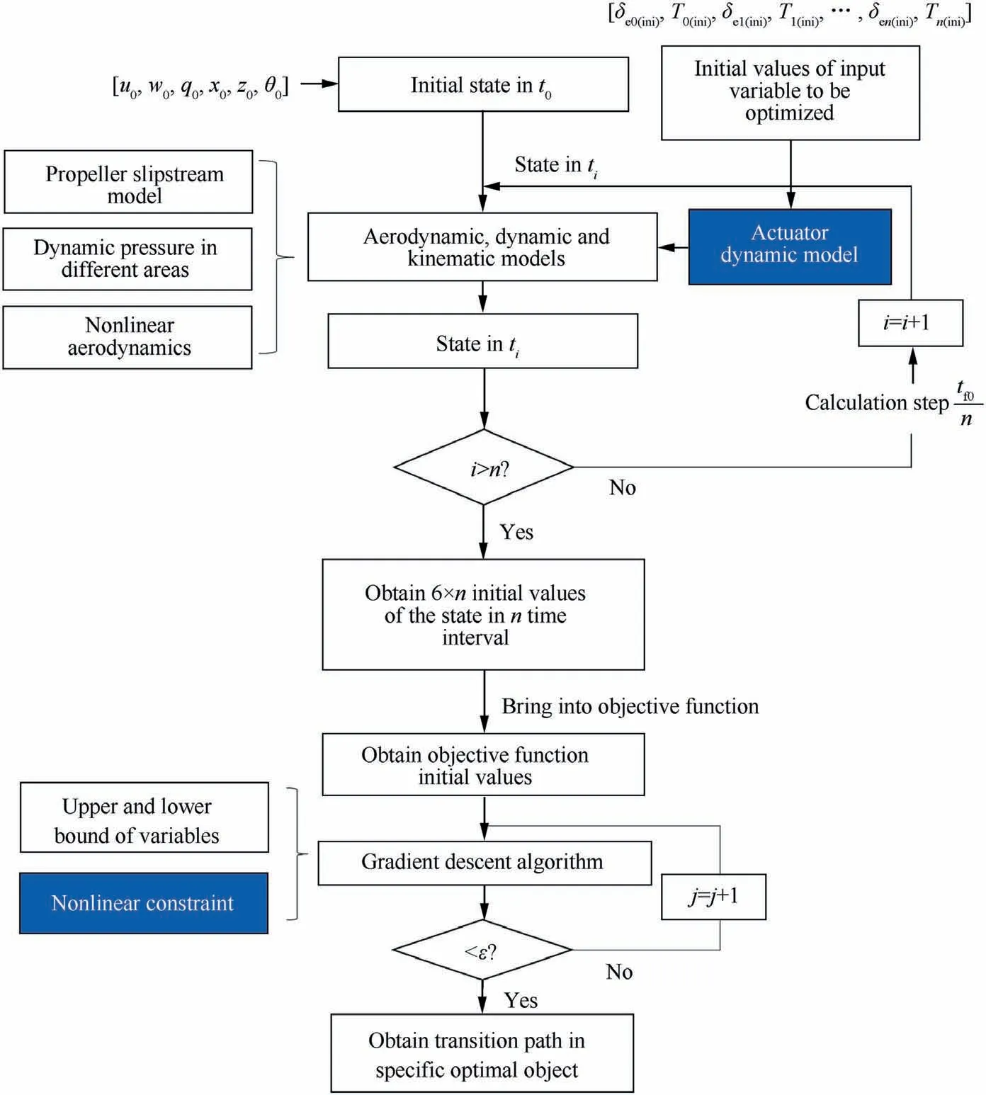
Fig. 11 Flowchart of optimization procedure.
3.5.1. Hover verification
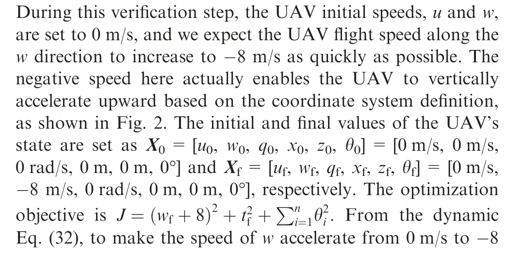
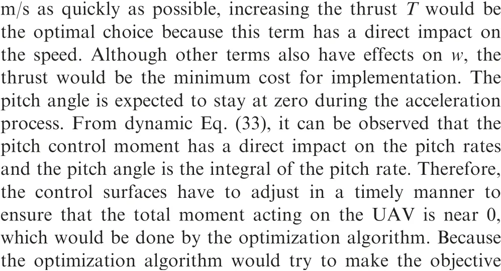
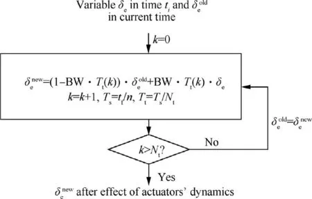
Fig. 12 Implementation of actuator dynamics.

The pitch angle remains near 0° during the entire acceleration process, which means that the UAV climbs vertically as expected.The final speed of 8 m/s is reached after 2.1 s.During the whole process, the thrust generated by the UAV never exceeds the thrust limitation defined in Eq.(30),the deflections of the control surfaces are within±25°, and these satisfy the input constraints defined in Eq. (39) and Eq. (40). Furthermore, to obtain the specified flight speed as soon as possible,the thrust is always within its limitation as expected. From Fig.14,it can be observed that T and Tlimitdo not fit with each other because Tlimitfor plotting in Fig.14 is consistent with the APC data, while the actually used Tlimitis consistent with Eq.(30), as explained and illustrated in Fig. 5.
High final speeds w are tested to assess whether the solution process would generate reasonable results, and a comparison of the system input time delay and actuator dynamics with and without this consideration is also performed.
In Fig. 15, n represents the results that do not consider the system input time delay and actuator dynamics, and -15 and-12 are the expected final speeds w of -15 m/s and -12 m/s,respectively.

Table 3 Parameter setting of optimization procedure.
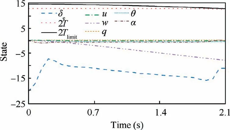
Fig. 14 States in hover verification.
At a final speed w of-12 m/s, the transition time with and without consideration of the effects of the system input time delay and actuator dynamics is 3.62 s and 3.27 s, respectively.Actually, the response from the sensor data to the actuator output cannot be immediately realized in the real system.Therefore, the results considering the above factors in this study are closer to the reality.Furthermore,it is observed that regardless of whether the final speed w is-12 m/s or-15 m/s,the pitch angle always deviates from the desired 0°. This phenomenon becomes more obvious when the final speed w is-15 m/s, and the UAV has to adjust the pitch angle to reach the desired final speed.This relatively large pitch angle change indicates that the UAV could not attain the desired objective.As shown in Fig.7 and the aforementioned analysis,the UAV maximal climbing speed is approximately 12 m/s, which explains why the pitch angle is so large when the final desired speed is -15 m/s. From this perspective, the UAV maximal ability can be assessed based on whether the final states match the desired states to a certain extent.
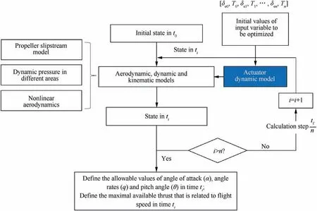
Fig. 13 Implementation of nonlinear constraints.
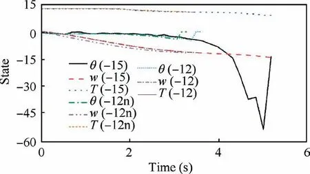
Fig. 15 Hover flight computation verification.
3.5.2. Forward-flight verification
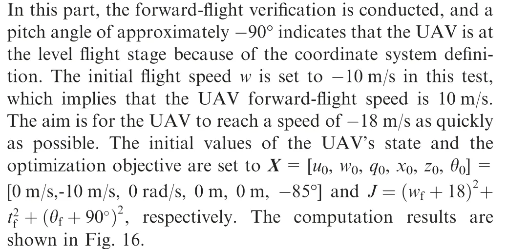
It is found that for the UAV to reach the desired speed as quickly as possible, the thrust always reaches its maximal value.Fig.16 shows that a mismatch between T and Tlimitdoes not occur, as shown in Fig. 14 because at an initial speed of-10 m/s,the maximally available thrust attained is lower than 6.25 N. Hence, Tlimitbecomes the upper bound for the UAV.The deflections of the control surfaces are within±25°,which means that the input boundary is satisfied. No unreasonable thrust and control surfaces fluctuations occur, which indicates the rationality of the result. Based on Eq. (43) and the pitch angle,as shown in Fig.16,it is determined that the pitch angle is restricted to-100°and,as expected,only small-angle diving is allowed.
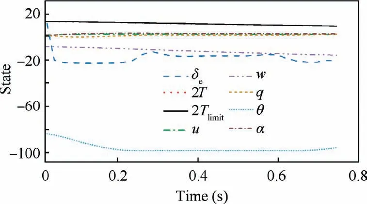
Fig. 16 Froward-flight computation verification.
According to the results of the hover and forward-flight stages, it is concluded that the solution process proposed in this study is feasible and reasonable. Therefore, the transition characteristics of the tail-sitter UAV are analyzed below.
3.6. Transition computation results and discussion
3.6.1. Forward transition
The UAV’s altitude may increase, remain approximately unchanged, or descend during the forward transition process,and these different situations correspond to distinct working conditions.Due to safety considerations,the transition process involving diving is not specifically analyzed because this transition type is not desired. In the case of an altitude decrease,the minimum time consumption is considered, and this also tests the UAV’s limits to a certain extent. In the case of an approximately constant altitude, a minimum altitude change is set as the optimization goal to establish a relatively gentle strategy. In regard to an altitude increase, the final altitude and minimum time consumption are considered to ensure that the UAV reaches the specified altitude as quickly as possible,which also reflects the ultimate UAV ability. Based on the above considerations, three different objective functions are defined, as listed in Table 4.
The UAV initial state is defined as X=[u0, w0, q0, x0, z0,θ0]=[0 m/s, 0 m/s, 0 rad/s, 0 m, 0 m, 0°]. Objective function J1requires the UAV to finish the transition as soon as possible.An extra altitude change constraint is added to objective function J1, which defines objective function J2. In objective function J3, the final expectation of the flight speed is changed to the final altitude, which helps the UAV to climb to the specified altitude as quickly as possible.
From Eqs.(31)–(33),thrust T is used to accelerate the UAV and pitch moment, which involves the deflection of control surfaces, and is used to change the UAV’s pitch angle. To make the UAV transit from the hovering to the forward flight stage in a short time, the thrust and deflection of the control surfaces need to reach their maximal values as quickly as possible to generate higher control force and moment. Furthermore, the UAV’s gravity must be compensated for by the lift and gravity components during the forward transition. Therefore, the thrust and control surfaces could not directly reach their maximal values without a plan. Otherwise, unexpected changes in the angle of attack,which would lead to inadequate lift, would make the transition unsafe. The planning for the thrust and control surfaces is made by using the objective algorithm.The numerical results of objective function J1are shown in Fig. 17.
Fig.17(a)shows that to ensure that the UAV completes the transition as quickly as possible, the maximal thrust is always employed to accelerate the UAV. However, under the minimum time requirement,an overly rapid pitch angle adjustmentchanges the direction of the thrust line too quickly. A low flight speed does not allow the wing to generate enough lift to balance the UAV gravity. Therefore, altitude loss occurs.During the entire transition process, the maximal angles of attack within and outside the propeller slipstream are 5.2°and 31°, respectively. The propeller slipstream plays a critical role in generating lift during the transition. Fig. 17(b) shows that the altitude change is smaller than 3 m,and the transition time is approximately 1.5 s.The altitude loss is not too large in this study because the UAV is relatively lightweight. Furthermore, the transition trajectories at the different initial flight speeds are also analyzed, and eight groups of initial speeds are considered.
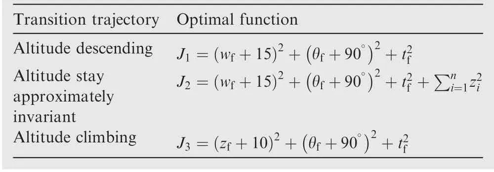
Table 4 Definition of optimal function.
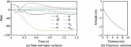
Fig. 17 Forward transition process under J1.
The trajectories and time consumption levels for the different initial states are shown in Fig.18 and Table 5,respectively.
It is observed that the UAV’s altitude decreases if it transforms from the complete hover stage, which implies that the initial values of u and w are both 0 m/s. However, if the UAV exhibits appropriate initial speeds, the altitude loss is greatly improved.This helps the UAV overcome the space limits of specific working environments. Table 5 indicates that an initial negative w value, which actually corresponds to an upward speed,allows the UAV to complete the transition process faster. In contrast, if the vehicle exhibits an initial downward speed, the UAV requires much more time to finish the transition process,which could also lead to a more severe altitude loss. Furthermore, if the UAV has a positive u value at the beginning of the transition process, the altitude could also decrease because at the start of the UAV transition,a positive u value endows the UAV with a velocity component along the altitude decrease direction in the inertial frame.
The computation results under optimal objective function J2are shown in Fig. 19.
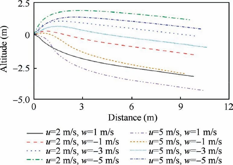
Fig. 18 Transition trajectories at different initial states.

Table 5 Transition time at different initial states.
The result in Fig. 19 represents a tradeoff between a fast transition and altitude maintenance, indicating a relatively gentle transition. The transition completion time is approximately 1.78 s. Compared to the transition time under J1, the altitude loss is slightly improved by increasing the transition time under J2. During this transition process, the maximal angles of attack within and outside the propeller slipstream are 5.2° and 29°, respectively. Based on the pitch angle variation in Fig. 17(a) and Fig. 19(a), it is observed that the UAV should not decrease its pitch too quickly to avoid a notable altitude loss.Moreover,a small pitch angle variation also benefits the angle of attack outside the slipstream,which is crucial for lift generation by the wing.
The computation results under optimal object J3are shown in Fig. 20.
Based on the Fig.20,the pitch angles do not decrease gradually, as shown in Fig. 17(a) and Fig. 19(a). Under the objective of climbing to a specific altitude as quickly as possible,the UAV implements the following actions. The UAV accelerates to reach a near-target altitude, and the control surfaces then enable the UAV to pitch down to finish the transition process.These results also verify the rationality of the entire computation process. The transition completion time is related to the desired final altitude, and a higher or lower final altitude affects the transition time. In this particular computation,the transition completion time is approximately 2.4 s.
The time is considered in the above three objectives,and the results reflect the limits to the UAV’s ability to a certain extent.Although only limited initial values are considered in this computation, other corresponding results may also be obtained with the method proposed in this study. The computation results cover both the time dependent pitch angle and the actuator variation during the transition process.These values could be adopted as reference values during the real flight tests.
3.6.2. Backward transition
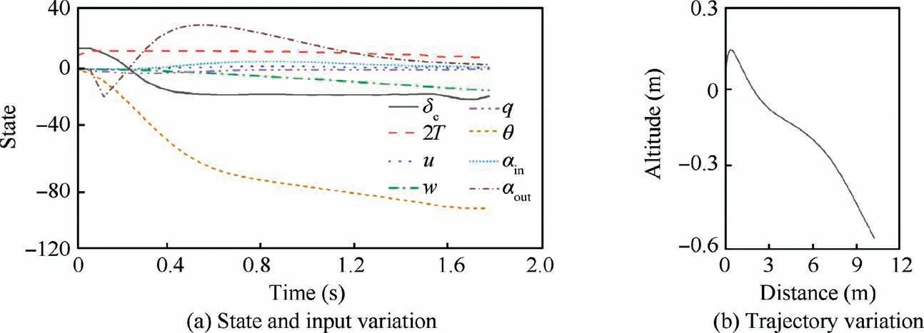
Fig. 19 Forward transition process under J2.
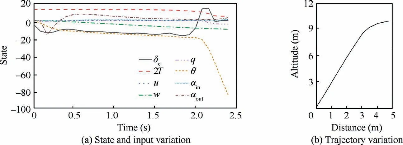
Fig. 20 Forward transition process under J3.

Table 6 Definition of optimal function.
In this section, the backward transition process is examined.Considering that the initial flight speed during forward flight is relatively high,backward transition always results in an altitude increase. The three different transition objectives are listed in Table 6.
The UAV initial states are defined as X=[u0,w0,q0,x0,z0,θ0]=[0 m/s, -15 m/s, 0 rad/s, 0 m, 0 m, -85°]. Objective function J1mainly tests the altitude increase during transition without any extra constraints. An altitude constraint is added to J1to establish a new objective function, J2, to improve the relatively high energy consumption. The time constraint in J3tests the fast-backward transition process.
The computation results under optimization objective function J1are shown in Fig. 21.
It is observed that if no extra constraint is added to the optimization function, the initial flight speed results in a relatively large altitude increase. The transition completion time is approximately 4.97 s, which depends on the initial flight speed. The final altitude is approximately 20 m. This is very disadvantageous from the perspective of reducing the energy consumption. During the transition process, the angles of attack of the wing within and outside the propeller slipstream are 8° and 67°, respectively. The reason for the large angle of attack out of the propeller slipstream is that when the pitch angle approaches 0°, a relatively high linear speed remains along u direction.
The computation results under optimization objective function J2are shown in Fig. 22.
Compared to the results shown in Fig. 21(b), the altitude increase is greatly improved, and the transition completion time is approximately 4.2 s, which is easier to adapt to a particular flight environment.The altitude exhibits downward and upward trends, because the UAV attempts to reduce the total altitude variation.
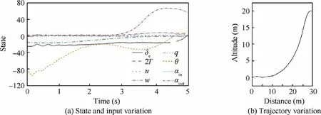
Fig. 21 Backward transition process under J1.
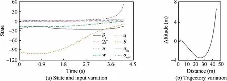
Fig. 22 Backward transition process under J2.
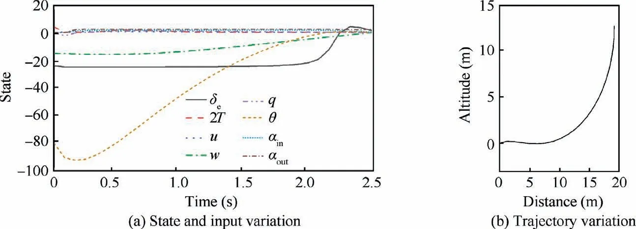
Fig. 23 Backward transition process under J3.
The computation results under optimization objective function J3are shown in Fig. 23.
Based on the thrust variation shown in Fig. 23(a), it is found that to reduce the UAV flight speed to 0 m/s as soon as possible, which is the hover stage, the thrust is quickly reduced. The efficiency of the control surface primarily depends on the initial flight speed. Although the UAV is required to immediately increase the thrust after the transition,the transition process is indeed completed under this specific optimization objective. The transition completion time is approximately 2.47 s which is the shortest time among the above three transitions, and the altitude increase is smaller than 15 m.
3.7. Effects of conceptual parameter
The UAV conceptual parameter mainly affects the maximal thrust, UAV gravity, pitch damping coefficient, coefficient of the control surface and UAV lift-drag force characteristics.In this section, the effects of the UAV conceptual parameter are examined at the forward transition stage and under objective function J1.The conceptual parameters of the original and new systems are listed in Table 7.
To better illustrate the effects of the conceptual parameter on the transition trajectories, only one parameter is changed at a time,and the results are compared to those of the original system.Each parameter is changed twice,one is larger and the other is smaller than the original system to illustrate the effects of conceptual parameter changes better.The UAV initial state is defined as X=[u0,w0,q0,x0,z0,θ0]=[0 m/s,0 m/s,0 rad/s,0 m, 0 m, 0°]. The effects of the other conceptual parameters could also be calculated by the above methods. The results are shown in Fig. 24. C1 to C6 are the results whereby only a specific parameter is changed, and OS are the results of the original system. The up arrow and down arrow in Fig. 24 are consistent with the definition in Table 7, which represent different conceptual parameter changes.
Fig. 24 shows that, for the same initial state and objective function, increasing the UAV gravity, increasing the absolute value of the drag coefficient slop, or decreasing the value of the pitch damping coefficient will result in a greater altitudeloss and longer completion time during the transition process.Moreover,decreasing the gravity by approximately 25%under the same objective function would cause the UAV to climb slightly, and this conceptual parameter change also leads to the minimal altitude change in all these results. Decreasing the maximally available thrust would lead to longer transition time and more severe altitude losses because the margin of manipulation is reduced. The changes of the pitch damping coefficient also have relatively large effects. Therefore, from the perspective of the conceptual design,to resolve the altitude loss problem under specific objective functions, the takeoff weight of the UAVs should be reduced. The quantitative relation between the altitude change and takeoff weight is obtained by defining different initial takeoff weights. If the UAV takeoff weight cannot be changed, an airfoil with better drag characteristics, i.e., a smaller drag coefficient slope or zero-value lift-drag coefficient, should be chosen. The pitchdamping characteristics of the UAVs are affected by several conceptual parameters,including the center of gravity and airfoil characteristics,and different aspects must be simulated for the UAV pitch damping characteristics. However, increasing the motors’ maximal thrust, i.e., choosing a different propulsion system,could enable the UAV to accelerate more rapidly,and more lift could thus be generated to maintain the UAV gravity.Increasing the lift coefficient could also reduce the altitude loss by generating more lift, and this could also be achieved by choosing an appropriate airfoil. The coefficient of the control surfaces imposes a limited effect on the transition path at this particular transition stage. The reason is that the generated control moment is sufficient to attain the desired pitch angle under the given objective function.In regard to the other conceptual parameters,such as the energy consumption,the results could also be analyzed based on a more sophisticated model with the method described in this study.Although only the altitude and distance results are presented here,other state parameters such as the pitch angle,flight speed and actuator outputs could also be determined with the above approach.

Table 7 Conceptual parameters of UAV.
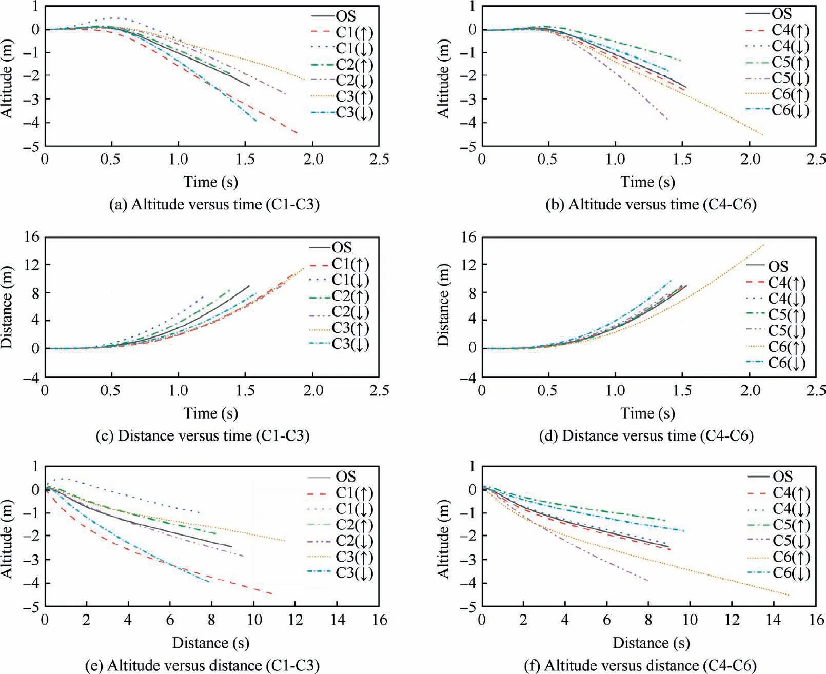
Fig. 24 Effect of conceptual parameter.
3.8. Comparison of static and dynamic results
In this section, the curves of the pitch angle versus the flight speed during the transition process are compared between the static and dynamic results. In the dynamic calculations,the initial states of u and w occur in [-5,5] m/s and different initial values are then substituted into the six objective functions mentioned above. The results are shown in Fig. 25.The forward transition results are mainly shown in the left bottom of the center of Fig.25 and the backward transition results are largely shown in the upper right of the center of Fig. 25.
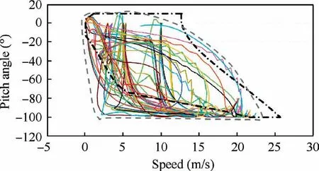
Fig. 25 Dynamic results of pitch angle versus speed.
The dynamic results are roughly represented by the gray dashed line,as shown in Fig.25 which is an approximate range plotted according to the computation results mentioned above.Therefore, the dashed line is assumed to reflect the UAV dynamic transition boundary in this study. Considering that the results are only computed based on finite initial values,Fig. 25 is just a sketch map, and more complete results can be obtained by computing different initial states. The results depicted in Fig. 7 are also shown as the black dotted dashed line in Fig.25 to better illustrate the difference between the static and dynamic analysis results.It can be clearly observed that the dynamic results during the transition can violate the boundary of the static results. The reason is that acceleration exists in the dynamic analysis, while acceleration could not be considered in the static analysis. Furthermore, the initial and final states of the dynamic analysis never exceed the static boundary because the angular rate and linear velocity are assumed constant at the end of the transition. Therefore, to better understand the transition characteristics of the tailsitter UAV,a combination of static analysis and dynamic analysis is more comprehensive, and these two different analysis approaches should be used for different purposes,as discussed in this study.
4. Conclusions
A study of the transition characteristics,including the forward and backward transition processes,of a tail-sitter UAV is conducted. Both static and dynamic analysis methods are applied to analyze the transition characteristics from different perspectives. Considering the UAV’s aerodynamic complexity, the genetic algorithm is adopted to resolve the static trimming problem, and the steady state of the UAV during transition,which could be adopted to verify the rationality of the dynamic analysis results,is determined.The effects of the propeller slipstream are specifically modeled and considered in the static analysis.
The UAV’s physical properties, including the system input time delay and actuator dynamics considered by a few researchers, are modeled and studied in the dynamic analysis.Considering that the system input time delay greatly complicates the optimization process, an equivalent first-order transfer function is considered instead. Furthermore, the transition completion time is often not known beforehand. Therefore,both the actuators’ manipulations at different time and the transition time are defined as the variables to be optimized.The gradient descent method is employed to generate smooth and reasonable results. The obtained analysis results with and without considering the system input time delay and actuator dynamics are assessed through hover flight verification. The results reveal that the transition time is longer than that without considering the above physical properties and UAV manipulation and state differences are also observed. Several typical transition processes are analyzed, various optimization objective functions are defined, and the acquired analysis results are applicable under specific working conditions. The desired pitch angle, flight speed and actuator output of the UAV during the transition process are also calculated.The desired pitch angle and flight speed should be considered when designing transition schemes, and in regard to the controller, the desired actuator output could be set as the actuators’ trim value to alleviate the control stress to a certain extent.
The effects of different conceptual parameters on the transition characteristics are analyzed and the quantitative results are used to provide suggestions for the conceptual design,which may facilitate UAV’s weight determination, motor selection,etc.at the initial aircraft design phase.The combination of static and dynamic analysis methods also demonstrates the necessity of conducting a complete transition analysis of the tail-sitter UAV.
The effects of external disturbances on the transition characteristics during real flight tests and the trajectory planning on the entire flight will be investigated in future research.
Declaration of Competing Interest
The authors declare that they have no known competing financial interests or personal relationships that could have appeared to influence the work reported in this paper.
Acknowledgements
This study was supported by the Natural Science Basic Research Plan in Shaanxi Province of China (No.: 2019JQ-411) and the Fundamental Research Funds for the Central Universities, China (No.: 300102259306).
 CHINESE JOURNAL OF AERONAUTICS2021年10期
- CHINESE JOURNAL OF AERONAUTICS的其它文章
- Direct dynamic-simulation approach to trajectory optimization
- A strong robustness open-circuit fault diagnosis strategy for novel fault-tolerant electric drive system based on d-q-axis current signal
- Nonlinear vibration response characteristics of a dual-rotor-bearing system with squeeze film damper
- Ground maneuver for front-wheel drive aircraft via deep reinforcement learning
- Numerical simulation of a UAV impacting engine fan blades
- Recent advances in precision measurement &pointing control of spacecraft
