Nonlinear vibration response characteristics of a dual-rotor-bearing system with squeeze film damper
Xinxing MA, Hui MA, Hiqin QIN, Xumin GUO, Chengung ZHAO,Mingyue YU
a School of Mechanical Engineering and Automation, Northeastern University, Shenyang 110819, China
b Institute of Vibration, Shock and Noise, Shanghai Jiao Tong University, Shanghai 200240, China
c Key Laboratory of Vibration and Control of Aero-Propulsion System Ministry of Education, Northeastern University, Shenyang 110819, China
d Department of Aeronautical Mechanics,Naval Aeronautical and Astronautical University Qingdao Campus,Qingdao 266041,China
KEYWORDS dual-rotor;rolling bearing;squeeze film damper;finite element method;vibration response
Abstract Rolling bearing and Squeeze Film Damper (SFD) are used in rotor support structures,and most researches on the nonlinear rotor-bearing system are focused on the simple rotor-bearing systems. This work emphasizes the comparative analysis of the influence of SFD on the nonlinear dynamic behavior of the dual-rotor system supported by rolling bearings. Firstly, a reduced dynamic model is established by combining the Finite Element (FE) method and the freeinterface method of component mode synthesis. The proposed model is verified by comparing the natural characteristics obtained from an FE model with those from the experiment. Then,the steady-state vibration responses of the system with or without SFD are solved by the numerical integration method. The influences of the ball bearing clearance, unbalance, centralizing spring stiffness and oil film clearance of SFD on the nonlinear steady-state vibration responses of the dual-rotor system are analyzed.Results show that SFD can effectively suppress the amplitude jump of the dual rotor system sustaining two rotors unbalance excitations. As the ball bearing clearance or unbalance increases, the amplitude jump phenomenon becomes more obvious, the resonance hysteresis phenomenon strengthens or weakens, the resonant peaks shift to the left or the right,respectively. SFD with unreasonable parameters will aggravate the system vibration, the smaller the oil film clearance, the better the damping performance of the SFD, the larger the centralizing spring stiffness is, the larger resonance amplitudes are.
1. Introduction
Dual-rotor systems composed of the Low-Pressure (LP) rotor and High Pressure (HP) rotor are widely used in aero-engine.The LP and HP rotors are connected by an inter-shaft bearing which will lead to the coupling vibration of dual rotors. In order to reduce the vibration of dual-rotor systems, the Squeeze Film Damper (SFD) is often employed in some types of aero-engines. However, ill-suited parameters of SFD can cause severe nonlinear vibration which can threaten the safe operation of the aero-engine. Many scholars have carried out in-depth research on the modeling of dual-rotor systems,vibration characteristics of dual rotors under unbalance or rubbing conditions and the vibration reduction mechanism of SFD and have achieved fruitful results1–4.
Some researchers adopted the lumped-parameter method to establish a dynamic model of dual-rotor systems5–10. Ignoring the gyroscopic effect,Hou et al.5built a dynamic model of the dual-rotor system with four Degree of Freedoms (DOFs) and analyzed the primary resonance responses using the frequencydomain method.Wang et al.6,7established lumped-parameter models of dual-rotor systems with 11-DOFs and 18-DOFs;and studied the nonlinear vibration behaviors of the systems under rubbing or misalignment fault by the Runge-Kutta method. Gao et al.9proposed an 8-DOFs dynamic model of a dual-rotor system with inter-shaft bearing faults; and analyzed the effects of the defects of inner and outer races on the nonlinear vibration behaviors of the system. Hu et al.10developed a 5-DOFs model and focuses on the response of rotor rotational degrees of freedom, the results prove that the nonlinear bearing force model has a significant impact on the system dynamics simulation.
Compared with the lumped-parameter method, the FE method has great advantages in simulating the complicated dual-rotor structures in aero-engine and is the most widely used method in present studies1,2,11–16. Yu et al.1established an FE model of a dual-rotor system using beam, mass and spring elements in ANSYS software and analyzed the dynamic responses of the dual-rotor system considering sudden unbalance and inertia asymmetry caused by the fan blade out.Yang et al.2,11adopted Euler–Bernoulli beam elements to establish FE models of dual-rotor systems under rubbing conditions.Aiming at a simple dual-rotor system, Fei et al.12built its FE model and analyzed the natural characteristics and vibration responses during the run-up. Adopting beam elements to discretize the shafts and casing, Wang et al.13established a dynamic model of the dual-rotor-casing system and analyzed the vibration responses due to blade-tip rubbing. In order to improve the calculative efficiency of an FE method, different model reduction methods were also employed such as the proper orthogonal decomposition method, modal synthesis method14–17. Sun et al.15proposed a reduced-order FE model and studied the rubbing-induced nonlinear vibration by the frequency-domain method. Wang et al.16established a reduced-order model of the dual-rotor-SFD system by combining the FE method and modal synthesis method and solved the nonlinear vibration responses of the system.
In general, the support structures of gas turbine includes rolling bearing (ball or roller) and SFDs, which can be simulated by nonlinear Hertz contact force and oil film force. Anisotropy is an inherent characteristic of support structures due to the dynamic characteristics of the oil film for SFDs or due to the time-varying contact of the rolling elements in the rolling bearing. It is worth noting that the ball bearing is hardening bearing, which means the amplitude jump phenomenon will occur. In the process of acceleration, the amplitude gradually increases to the peak value in the supercritical region,and then suddenly drops to a low value. During deceleration, the amplitude is very low until it suddenly jumps up. This type of system is liable to undergo quasi-periodic motion,the clearances, waviness of rolling elements and unbalanced forces bring a significant influence on the system stability18. In addition,the stiffness and damping coefficient of the support structure is easily affected by many factors, such as the assembly errors, load condition and temperature variation, especially when a squeeze film damper is used, the vibration responses of casing and rotor are analyzed in Refs.19,20under the influence of support uncertainty respectively.Therefore,it is necessary to explore the influence mechanism of rolling bearing and SFDs on the nonlinear vibration response of the dual-rotor system. However, the relevant research was mainly focused on the single rotor systems21–26, and most of the researches only focus on the influence of rolling bearing or SFDs on the system response, and lack of comparative study. Using the finite element method, Han and Ding21built a rotor/ball bearing system model, and their study showed that SFD can effectively suppress the amplitude of the transient response during flight maneuvers. On the basis of Ref.21, Han et al.22developed an elastic ring squeeze film damper-rotor model,and they found that ERSFD had a better dynamic performance than SFD in preventing bi-stable vibration of rotor.Considering the effect of fluid inertia, Chen et al.23analyzed the bifurcation behaviors of a rigid rotor-squeeze film damper system. Based on the general Reynolds equation and the Reynolds equation of conventional squeeze film damper, Zhou et al.24respectively established two dynamic models of the dual clearance squeeze film damper. And the consistency of the numerical solution of the two models was verified. Aiming at a flexible rotor system supported on squeeze film dampers,Zhang et al.4used the cell mapping method to complete a multi-objective optimal design. Zhou et al.25established a rotor model supported on ball bearings with Floating-Ring Squeeze Film Dampers (FSFD), and the results showed that FSFD can effectively prevent the bistable response. Zhou et al.26investigated the dynamics characteristics of a rotor supported on ball bearings based on two floating ring squeeze film dampers models,where one has a single oil film,and the other has a double layer oil film. Gao et al.27studied the dynamic characteristics of a flexible asymmetric rotor system considering the nonlinear supports of ball bearings and SFDs, results show that the coupled effects among the rotor, ball bearings and SFDs leads to the bistable phenomenon,amplitude jumping phenomenon and non-synchronous vibration.
Some scholars have carried out the research on the modeling and nonlinear vibration analysis of the dual-rotor or multiplerotor systems supported on ball bearing and SFD. Defaye et al.28discussed the effects of two kinds of dual-rotor structures and three SFDs for inter-shaft ball bearing on the vibration reduction and nonlinear vibration characteristics by experiment. In order to overcome the time-consuming deficiency of the numerical integration method,Hai and Bonello29developed an impulsive receptance method to calculate the time-domain vibration responses of a dual-rotor-SFD system.In the follow-up study, they proposed an improved harmonic balance method to calculate the frequency-main responses of the system30and verified the proposed method by experiment31and analyzed the effects of load and structural parameters on the vibration responses using the proposed two methods32.
From the above literature, it is shown that the roller bearing is simulated using the linear spring-damper in Refs.1,2,8,11,12,13,15 and nonlinear bearing force in Refs.5-7,9,10,16,17,and SFD is described using nonlinear oil-film force in Refs.16,17,29–32during the modeling of dual-rotor systems.However,it is not enough to pay attention to the mechanism of the nonlinear steady-state vibration response of the dual-rotor system with or without SFD contrastively. This is the inspiration of our research work. First, a finite element model of the dualrotor system with nonlinear bearings capable of describing the mechanical vibration resulting from unbalance is established.Then the implicit numerical method is adopted to solve the reduced dynamic equations of the dual-rotor system.Finally, at different rotational speeds, the effects of mass unbalance, ball bearing clearance, the centralizing spring stiffness and the oil film clearance of SFD on the nonlinear dynamic characteristics of the system are discussed.
2. Dynamic model of a dual rotor system supported by rolling bearing and SFD
2.1. FE model of a dual rotor system
In this section,the FE composed model of a dual rotor system mounted on rolling bearings with SFD is established.Fig.1(a)shows the schematic of a dual rotor-bearing system.There are five bearings in the system,bearing 1 installed at the front end of the LP rotor is simulated by the nonlinear ball bearing force; the inter-shaft bearing is built by the nonlinear roller bearing force;bearing 2,bearing 3 and bearing 5 are described by the linear springs and viscous dampers. The stiffness and damping are K2, C2, K3, C3, K5and C5, respectively. The SFD schematic is shown in Figs.1(b) and 1(c). In Fig.1(b), e denotes the journal eccentricity;θ and z are the circumferential and the axial coordinates. In Fig.1(c), Kais the stiffness of centering spring such as squirrel cage; Fbis nonlinear Hertz contact force of ball bearing and the detailed expression of Fbwill be introduced in the next section;Fsis nonlinear oil film force of SFD which generated between the outer ring of ball bearing and the SFD housing.mOand MLare mass of the ball bearing outer ring and LP rotor,respectively.L and C indicate the land length and oil film clearance of SFD.
The rotor segments are described by Timoshenko beam elements that adequately account for the rotary inertia and the gyroscopic effects. The LP rotor is dispersed into 62 sections with 63 nodes and 252 Degrees Of Freedom (DOF) in total.The HP rotor is divided into 28 sections with 29 nodes and 116 DOFs in total. Each node of LP or HP rotor has four DOFs, including two translational DOFs and two rotational DOFs. The model discretization and key nodes are shown in Fig. 2 (a) and the geometry and size of the key parts of the experimental installation are listed in Table 1 or Table 2.
In Fig.2(b),xA,yA,xB,yBand θxA,θyA,θxB,θyBdenote two translational DOFs and two rotational DOFs of nodes A and B. The displacement vector of an arbitrary beam element qeand disk qedcan be described as follows:
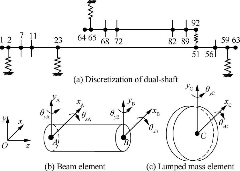
Fig. 2 Diagrams of discretization and elements.
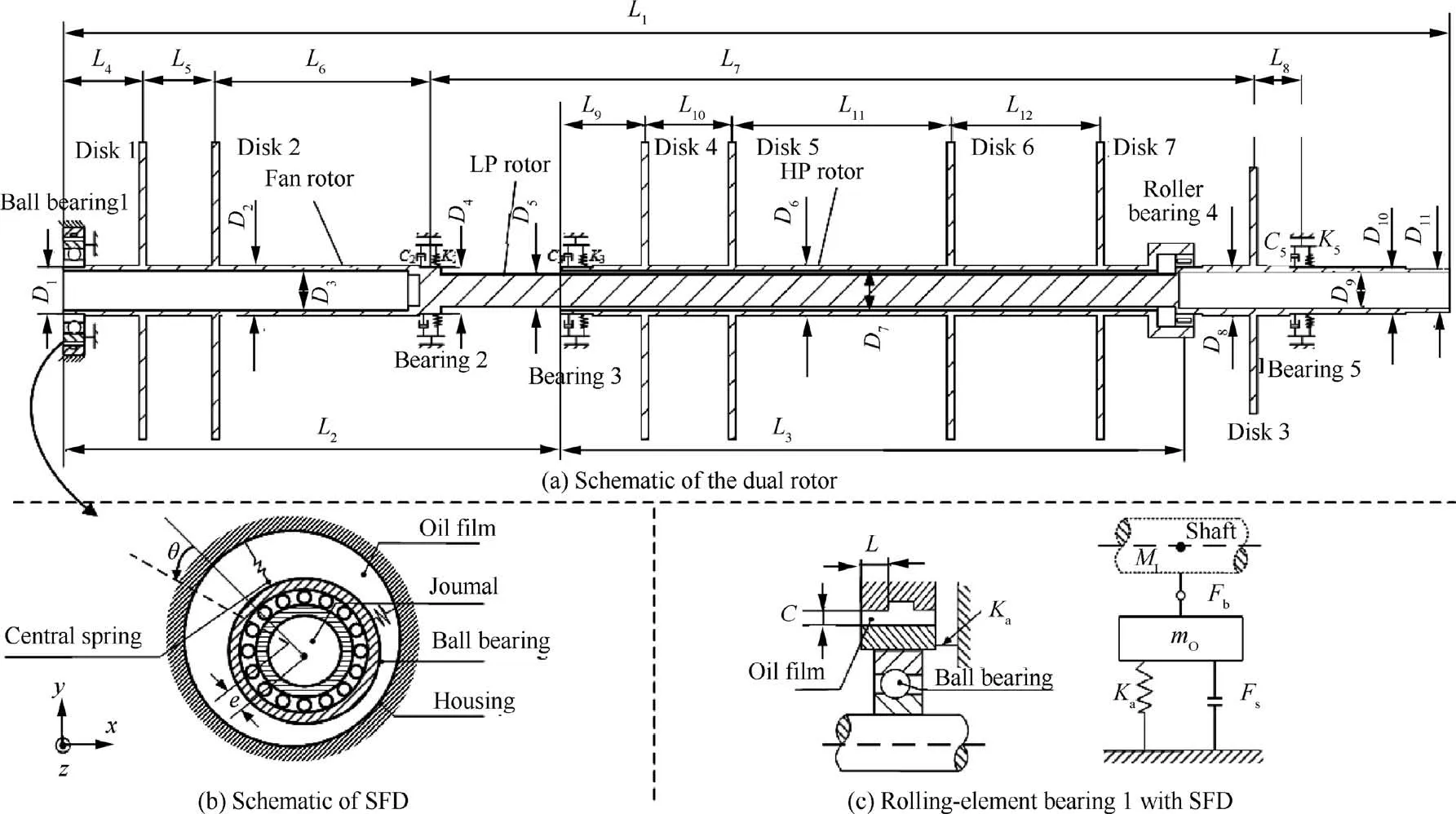
Fig. 1 Dynamic model of dual rotor system supported by rolling bearing with SFD.
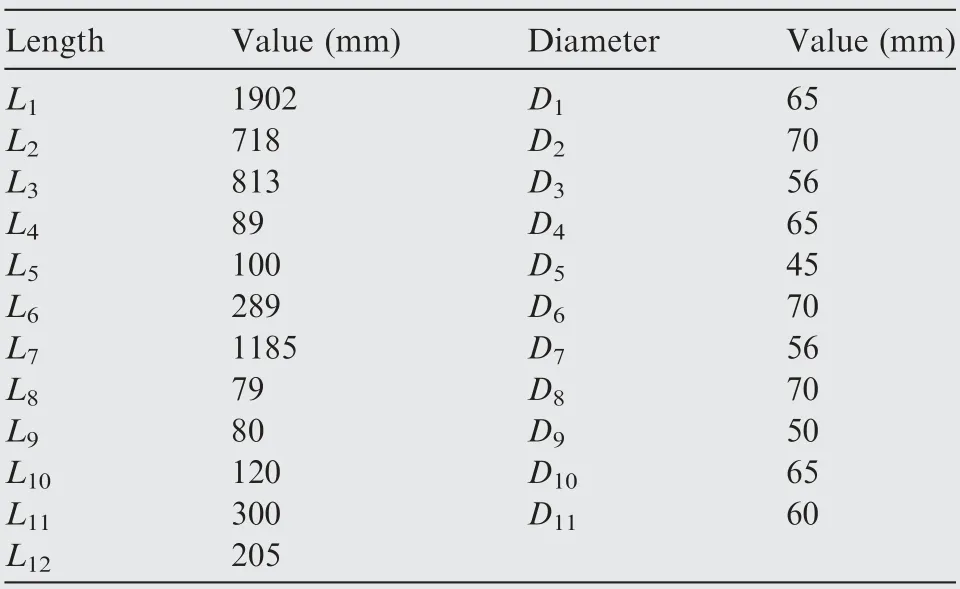
Table 1 Parameters of shaft.
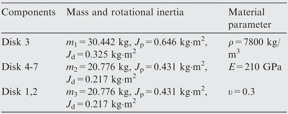
Table 2 Parameters of disks.

The specific description of the mass matrix,stiffness matrix and gyroscopic matrix for the Timoshenko beam element are given in Refs.13,21. The rigid disks are superimposed on the corresponding shaft nodes in the forms of lumped mass, each disk has four DOFs (see Fig.2(c)). Disk 1 and disk 2 are fan disks, disk 3 is the low-pressure turbine disk; disks 4, 5 and disks 6, 7 are the high-pressure compressor disks and the high-pressure turbine disks, respectively.
The governing equations of the LP rotor can be expressed as:

where ML,KL,CL,and GLare the mass,stiffness,proportional damping and gyroscopic matrices of the LP rotor,respectively;CL= aML+βKL; a and β are two scale coefficients; ωLis the rotational speed of LP rotor; qLand FLare the displacement vector and external load vector of the LP rotor, respectively.FLis the resultant force including the unbalance force Fu1and the support reaction force Fb1.


where R is radius of SFD journal,μ is the oil viscosity,h is the squeeze film thickness, ˙φ is the angular velocity.
The equivalent oil film force components Fsxand Fsyin x-and y-directions can be obtained by integrating the pressure distribution along with the circumferential and axial directions25:
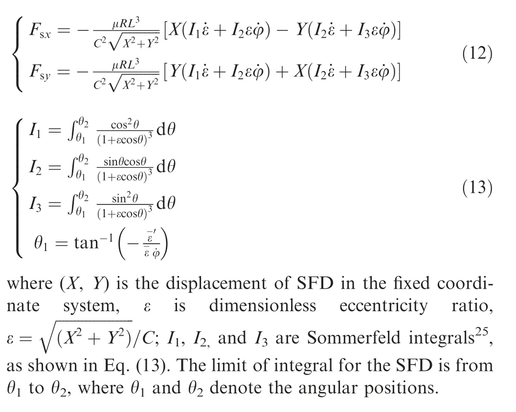
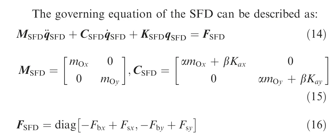
where MSFD, CSFD, and KSFDare the mass matrix, proportional damping matrix and stiffness matrix of the SFD, FSFDis the vector of external excitation. mOxand mOyare the lumped mass at the outer ring of the ball bearing in the xand y-directions; Kaxand Kayare the stiffness of central squirrel-cage spring in the x- and y-directions, respectively.Fsxand Fsyrepresent the oil film forces of SFD obtained from Eq. (12).
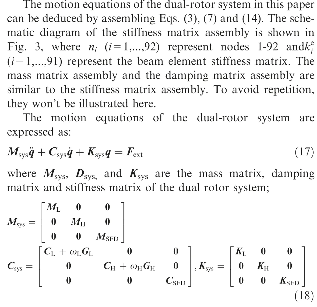
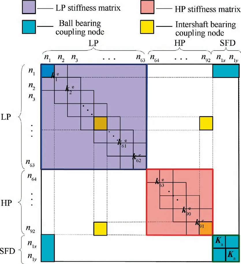
Fig. 3 Schematic diagram of stiffness matrix assembly.
q and Fextare vectors of displacement and external excitation.

2.2. Mathematical Models of ball bearing and inter-shaft bearing
A schematic of the ball bearing is shown in Fig. 4, where Nbdenotes the number of balls, ωcageis the angular velocity of the cage, R0, r, and G0are the radius of the outer ring, the radius of the inner ring and bearing clearance, respectively.In the ball bearing model, the point contact exists among the bearing inner or outer raceway and balls. The inner race of the ball bearing is jointed to the inner rotor,and the outer race of the ball bearing is jointed to the SFD.
According to the Refs.33,34, the nonlinear restoring forces Fbxand Fbygenerated in the x and y direction of ball bearing can be obtained as:
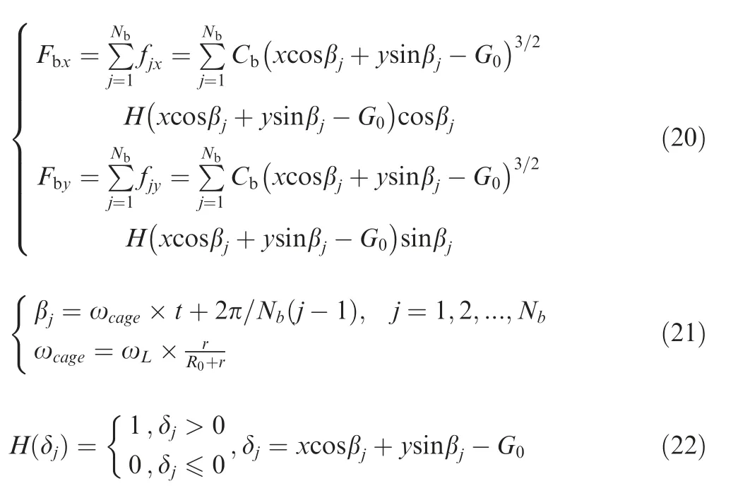
where Cbis the Hertz contact stiffness, which is related to the contact material and shape. βjis the position angle of the jth ball. x and y are the vibration displacements of the inner ring in x and y directions,respectively.δjis the contact deformation between the jth ball and raceway, H(δj) is Heaviside function.ωLis the angular velocity of LP rotor.
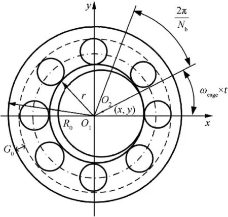
Fig. 4 Schematic of a ball bearing.
It is worth noting that x and y are the relative displacements, x=xB-xO, y=yB-yO. xB, yB, xOand yOare the displacement components in x- and y-directions of the journal and ball bearing outrace, respectively.
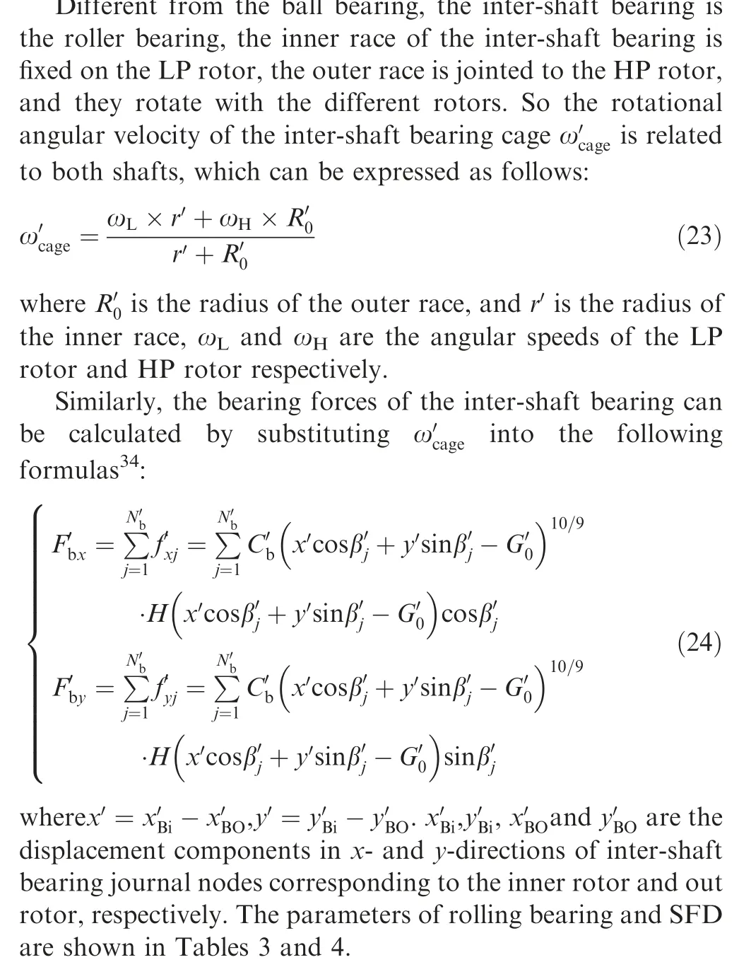
2.3. Model reduction and verification by experiment results
2.3.1. Model reduction
In this paper, Newmark-β time-domain integral algorithm is adopted to solve the motion equations of the dual-rotorsystem. Due to the motion equations relating the relative displacements and velocities at the SFD, Newmark-β algorithm is time-consuming when dealing with the large-order system sustaining the motion-dependent forces and other excitations acting on the linear part of the structure.Considering the nonlinear motion-dependent forces only act on several special supporting nodes, the free interface component mode synthesis can be used to reduce the dimension of the rotor to improve computational efficiency.

Table 3 Parameters of rolling bearing.

Table 4 Parameters of squeeze film damper.
The flow chart of the solution is shown in Fig. 5.
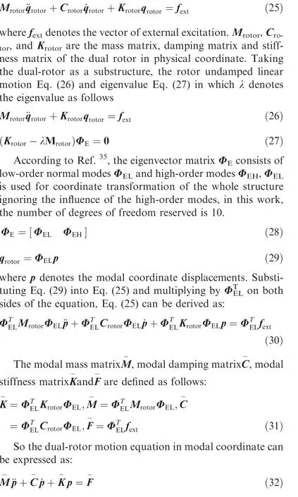
The equations of motion of rotor can be written as:
2.3.2. Verification of the dual rotor system model
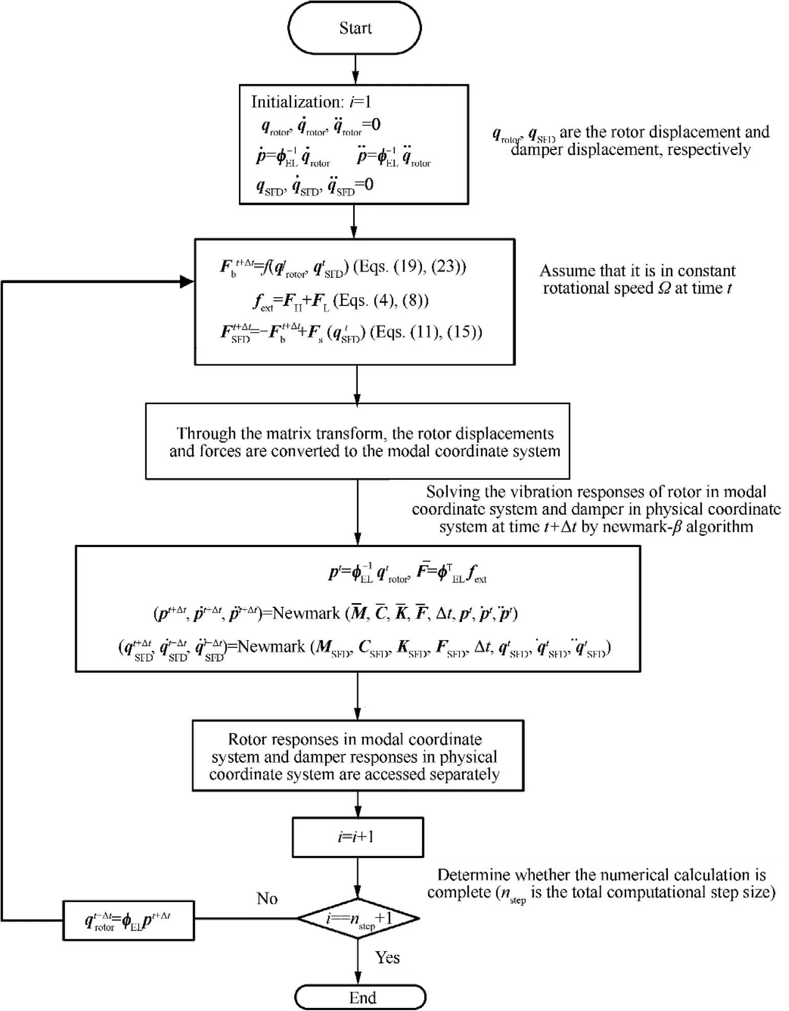
Fig. 5 Flow chart of dual rotor system solution.
In order to verify the proposed dual-rotor system model, the natural characteristics of the linear dual-rotor system are compared with the experimental results. A dual-rotor system test rig is shown in Fig. 6, which consists of a fan rotor, lowpressure turbine rotor, high-pressure rotor and connection,and support structure. The inner rotor is composed of a lowpressure turbine rotor and fan rotor, and the rotating shaft is thin and long.Because the mass is concentrated at both ends of the shaft, the bending characteristics are obvious; while the rotating shaft of the high-pressure rotor is short and thick,and the bending stiffness is relatively large.The two rotors are connected by inter-shaft bearings. The fan rotor is a disk-drumshaft hybrid rotor. The fan rotor and low-pressure turbine rotor are connected by a spline coupling and pass through the high-pressure rotor. The high-pressure rotor is a drumshaft. The inner and outer rotors are respectively driven by motors that can rotate in the same direction or in the opposite direction.The squeeze film damper is located at the front bearing of the fan rotor and it can be supplied by the oil supply device nearby. However, it was not supplied with oil in the experiment, so the experiments in this paper did not involve the squeeze film damper.
The first two order natural frequencies obtained from the developed model, ANSYS solid model and experiment are shown in Table 5. Due to the simplification of the model(e.g. the spline coupling is considered as a continuous shaft segment) and the calculation error of the supporting stiffness,the maximum error between simulation and experiment is 8.21%.It is acceptable and the effectiveness of the linearly supported dual-rotor system model is verified. Fig. 7 shows the corresponding mode shapes. The first-order mode shape of the system displays the first-order bending of the LP rotor.The second-order mode shape of the system shows the local bending of the front end of the LP rotor and the secondorder modal activity near bearing 1 is more obvious than that of the first order.
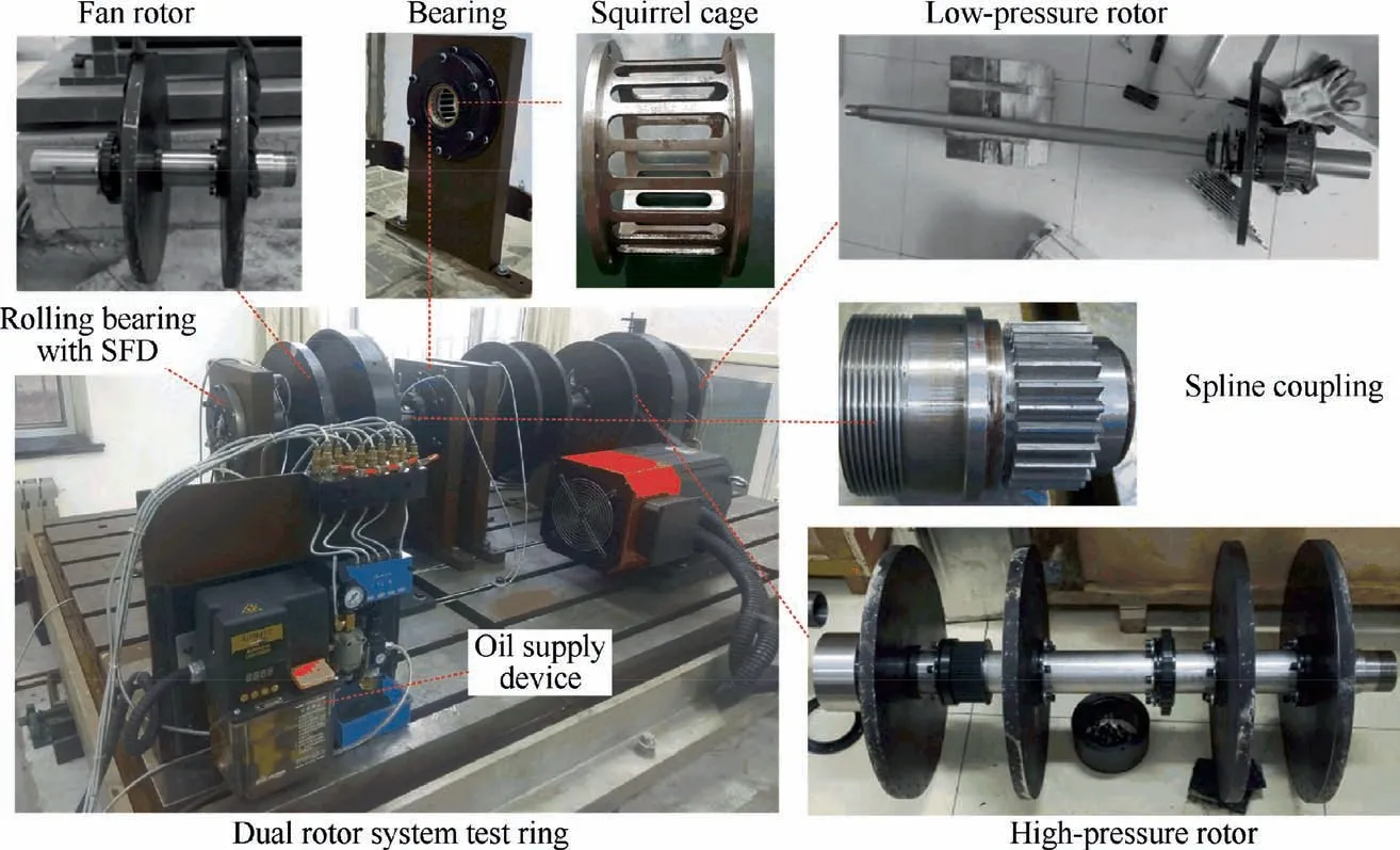
Fig. 6 Dual rotor system test rig.

Table 5 Natural frequencies comparison (ω=0 r/min).
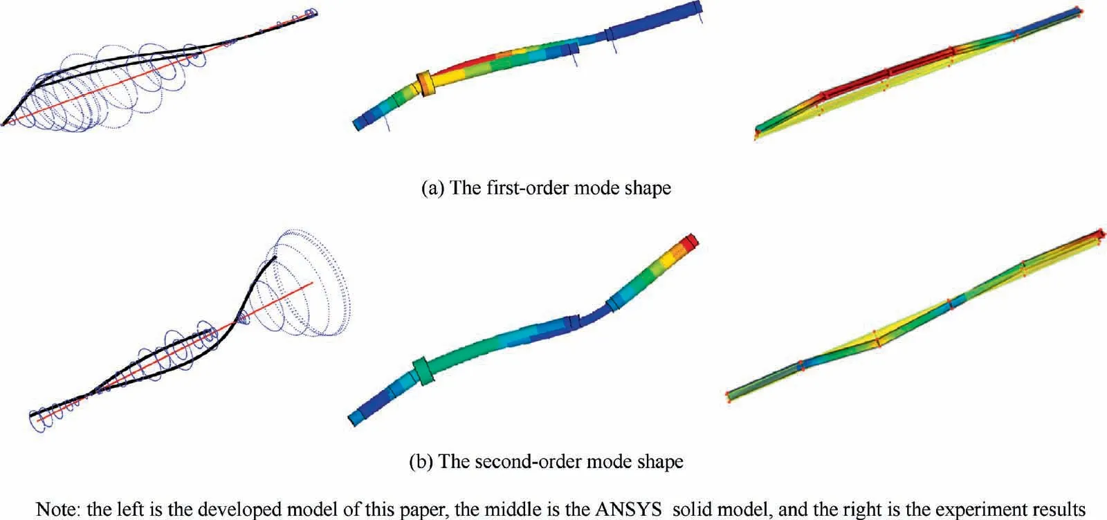
Fig. 7 First two order mode shapes.
Fig.8 and Fig.9 shows the amplitude-frequency and phasefrequency responses obtained from experiments during run-up and run-down. In the test, the eddy current sensor is used to measure the amplitude, the photoelectric sensor is adopted to measure the speed, and the reflective labels are respectively pasted on the discs of the HP and LP rotor. Two motors are respectively operated to drive the corresponding rotor rotation, speed up or down, and the vibration amplitude is measured. The Campbell diagram is solved using the same conditions as the test,the HP rotor imbalance or the LP rotor imbalance is used as the main excitation respectively. Fig. 10 displays the results of Campbell diagram. It should be noted that the HP rotor does not rotate and only the LP rotor rotates in Fig.10(a), on the contrary in Fig.10(b). The first two critical speeds of the developed model are in good agreement with that obtained from experiments (see Table 6), and the maximum relative error is about 6.8%. Actually, the bearing stiffness of static status is quite different from that of rotating status and there are some errors in the process of data acquisition. Therefore, the developed model is effective.
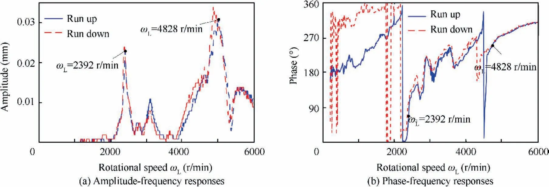
Fig. 8 Vibration responses of front vertical measuring point of low-pressure compressor rotor.
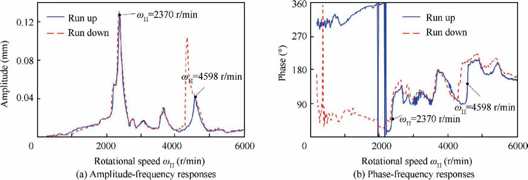
Fig. 9 Vibration responses of the vertical measuring point of high-pressure compressor rotor.
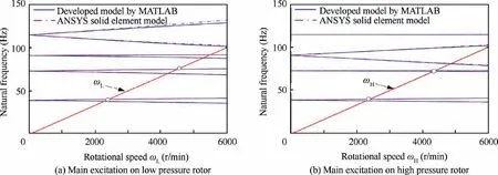
Fig. 10 Campbell diagram of system.

Table 6 Critical speeds comparison.
By the comparison of natural frequency and critical speeds,the linear dynamic model of the dual rotor system is verified.However, in actual working conditions, the HP or LP rotors respectively rotate and maintain a certain speed ratio. In the following analysis of the amplitude-frequency response, the HP and LP rotors is set to counter-rotation, and the speed ratio is-1.2.The Gyroscopic moments are related to the direction of rotation, the critical speeds are smaller because the influence of gyroscopic moments on dual rotor structures decreases in counter-rotation.The steady-state amplitudefrequency responses of each disk of the linear dual rotor system are shown in Fig. 11.
Fig.11(a) shows that the first two natural frequencies are excited in the amplitude-frequency responses of disk 1 and disk 2,and the first and third natural frequencies are excited in the amplitude-frequency responses of disk 3.The first two natural frequencies of the system are also excited primarily according to the amplitude-frequency characteristics of the HP rotor disks (except the turbine disk 7), as shown in Fig.11(b). In terms of computational efficiency, the calculation of the amplitude-frequency response of the reduced model takes 25.7 minutes, while the corresponding calculation of the amplitude-frequency of the unreduced model takes 409.8 minutes. It is clear that the calculation time on a personal computer with a 64 bit processor with 3.4 GHz clock frequency,4 cores (8 threads) and 16 GB RAM using the unreduced model increased by nearly 20 times comparing with that using the reduced model.
After replacing bearing 1 and inter-shaft bearing with nonlinear bearing forces, the frequency responses are shown in Fig. 12. The three resonance peaks of the system are close to the critical speeds of the rigid supported system,which verifies the correctness of nonlinear bearing force.However,due to the influence of the time-varying bearing force, the amplitude jump phenomenon occurs.And this phenomenon will be highlighted in the next section. The amplitude-frequency response calculation of the nonlinear reduced model takes 5.74 h,while the corresponding calculation of the amplitude-frequency of the unreduced nonlinear model takes 119.73 h minutes.
3. Steady-state responses of the reduced dual-rotor system with nonlinear bearings and SFD
In this section, the effects of different structural parameters such as bearing clearance, unbalance and centralizing spring stiffness on the steady-state responses of the dual-rotor system are investigated.The rotating speed changes from 780 r/min to 9060 r/min with an interval of 120 r/min. The Newmark-β numerical method is adopted to solve the reduced motion equations of the system.And the time domain waveforms,frequency spectra, rotor orbits, and spectrum cascades are used to analyze the dynamic characteristics of the system. The effects of squeeze film damper on the system nonlinear vibration characteristics, including the amplitude jump phenomenon and the resonance hysteresis, are analyzed.
3.1. Effects of unbalance on the system nonlinear response
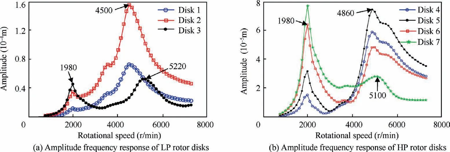
Fig. 11 Amplitude-frequency response of each disk in the linear dual-rotor system.
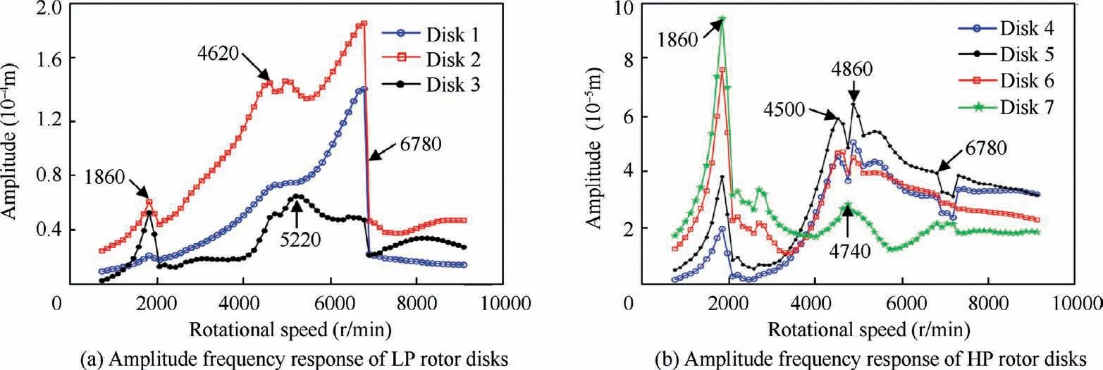
Fig. 12 Amplitude-frequency response of each disk in nonlinear dual-rotor system.
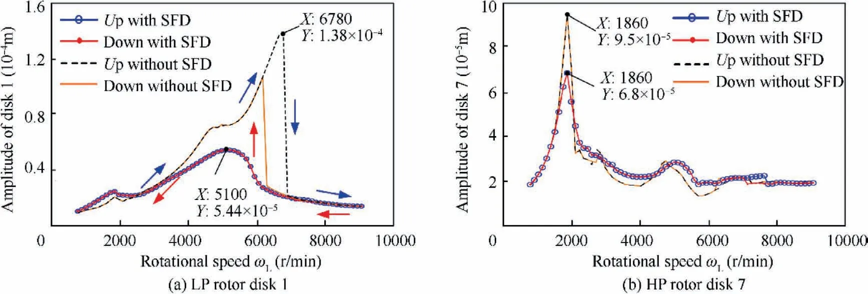
Fig. 13 Amplitude frequency responses comparison.
In order to illustrate the vibration damping performance of the SFD, the amplitude-frequency responses of LP-rotor disk 1 and HP-rotor disk 7 are shown in Fig. 13. By comparing the response curves, an interesting phenomenon is revealed that the amplitude jump of LP-rotor disk 1 is suppressed when the SFD is considered at the ball bearing position, see Fig.13(a), it is found that the second-order resonance amplitude of the system without damper is 7.22 × 10⁻⁵m, while the second-order resonance amplitude of the system with damper is 5.44 × 10⁻⁵m. The resonance peak of the inner rotor disk 1 is reduced by about 25%,the disk 1 jump phenomenon after the second-order resonance peak disappears, and the maximum amplitude of the system is reduced by more than twice.If the SFD is not considered,resonance hysteresis occurs.That is,the jump point of LP-rotor disk 1 during the run-down process without SFD lags behind the jump point during the runup process. Because the second-order modal activity near ball bearing is more prominent than that of the first order, the second-order resonance peak of LP-rotor disk1 reduced obviously. Fig.13(b) shows the amplitude frequency response curve of outer rotor disk 7. The first-order resonance amplitude of system without damper is 9.5 × 10⁻⁵m, the firstorder resonance amplitude of system with damper is 6.8 ×10⁻⁵m, the amplitude at the first-order resonance peak decreases by about 28%.It can be seen that the first-order resonance peak of HP-rotor disk 7 declines sharply and the amplitude-frequency response curve is smoother when the SFD is considered.
In order to observe the influence of unbalance on the vibration response characteristics of the system, the nonlinear frequency curves of the LP-rotor disk 1 under three different mass unbalance (U1,U2,U3)are obtained in Figs. 14-21. As shown in Fig.14(a), the amplitudes of disk 1 increase with the increase of unbalance, and the position of resonance peak shifts to the right,which shows an obvious hard characteristic.However, the amplitude jump phenomenon does not occur when the SFD is in consideration(see Fig.15(a)).In addition,Fig.14(a) also shows that the hysteresis will weaken with the increase of the unbalance.This is because the increasing unbalance force will weaken the nonlinear effect on the system caused by the ball bearing force. Comparing the amplitudefrequency response of disk 7 in two cases,it can be found that the laws of two cases are basically consistent and the amplitude jump phenomenon does not occur (see Fig.14(b) and Fig.15(b)).Thus,when the influence of parameter changes on the system nonlinear responses is considered, only the vibration responses of disk 1 are taken as the contrasted objectives in the following research.
Fig.16 and Fig.17 are the spectrum cascade corresponding to Fig.14(a) and Fig.15(a). Fig. 16 shows that the combination frequencies are abundant in spectrums, especially when the system is passing through the critical speeds. fHand fLare the rotation frequency of high and low pressure rotors.However, the combined frequency does not appear when the SFD has been introduced to the system, as shown in Fig. 17.In addition, it can be observed that the combination frequencies gradually disappear comparing the Figs.16(a), 16(b) and 16(c), which shows that the smaller the unbalance of the system, the stronger the support nonlinearity of the system.
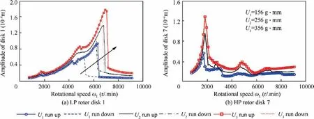
Fig. 14 Amplitude-frequency responses of the system without SFD under three unbalance conditions.

Fig. 15 Amplitude-frequency responses of the system with SFD under three unbalance conditions.

Fig. 16 Spectrum cascades of disk 1 under different unbalances without SFD.

Fig. 17 Spectrum cascades of disk 1 under different unbalances with SFD.

Fig. 18 Vibration responses of disk 1 without SFD at ωL =1860 r/min.

Fig. 19 Vibration responses of disk 1 without SFD at ωL=6780 r/min.

Fig. 20 Vibration responses of disk 1 with SFD at ωL=1860 r/min.

Fig. 21 Vibration responses of disk 1 with SFD at ωL=6780 r/min.
Fig. 18 and Fig. 19 shows the vibration responses of the disk 1 at ωL=1860 r/min and 6780 r/min without SFD,respectively.It can be observed from Fig.18,as the unbalance gradually increases, the rotor goes through quasi-periodic motion and periodic motion, respectively. When unbalance is small,the orbits are chaotic and the corresponding waveforms are aperiodic. The combination frequencies and fractional frequencies, such as fL+2fH, (fH-fL)/2, fH/2, are excited due to the nonlinear support.As shown in Fig.19,the orbit displacement is very small when the unbalance is 156 g∙mm, but in other two cases, the displacements become larger, this is because the amplitude jump phenomenon has occurred under the first conditions according to Fig.14(a), there are only two rotating frequencies in the spectrum.
Compared with Fig. 18 and Fig. 19, it can be seen from Fig. 20 and Fig. 21 that the rotor orbits are symmetric and petal-like. The waveforms at different conditions are periodic.There are only rotating frequencies fLand fHin the spectrum.It can be seen from the rotor orbits and spectrum that the use of SFD can reduce the vibration amplitude of the system and suppress the nonlinearity of bearing force.
3.2. Effects of ball bearing clearances on the system nonlinear responses
In the process of installation, small bearing clearance is unavoidable, which probably introduces strong nonlinearity.In order to demonstrate the influence of bearing clearance on the dynamics characteristics of the dual-rotor system, the steady-state unbalanced responses of the system from 780 r/min to 9060 r/min are calculated at different clearances G0(5 μm, 10 μm, 15 μm, and 20 μm) respectively.
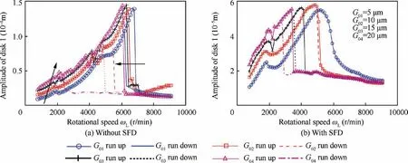
Fig. 22 Amplitude-frequency responses of disk 1 under four bearing clearances.
The results are illustrated in Fig. 22. Fig.22(a) shows that the amplitudes of the system raise and the position of second-order resonance peak shifts to the left with the increase of bearing clearance G0, which is caused due to the change of the ball bearing force. Eq. (20) indicates that the overall ball bearing force will decrease as the G0increases, the balls are not easy to contact the raceway steadily as the bearing clearance increase. This means the equivalent radial stiffness of the ball bearing reduces but the nonlinear effect is stronger.In addition, the hysteresis characteristic becomes prominent and the lag interval (frequency interval between two jumping frequency of ascending and descending speed) broadens obviously with the increase of the bearing clearance. The rotor vibration amplitudes are higher with larger clearance in the subcritical region but similar in the supercritical region.
When SFD is considered,the amplitude jump phenomenon of LP-rotor disk 1 begins to appear and become more and more obvious with the increase of the bearing clearance, as shown in Fig.22(b).The reason is that the increase of support clearance changes the bearing force and weakens the damping effect of squeeze film damper. It is noteworthy that when the G0=5 μm, the amplitude jump is under control in the amplitude versus speed curve.
Spectrum cascades under different bearing clearances are illustrated in Fig.23 and Fig.24.With the increase of the bearing clearance, the multiple frequency components appear, and it becomes obvious especially near the first two critical speeds(see Fig. 23). However, as shown in Fig. 24, the combination frequencies are inconspicuous. These phenomena show that the external damping introduced by the SFD not only reduces the vibration amplitude but also changes the nonlinearity of the system.
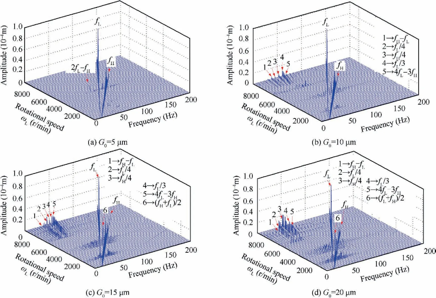
Fig. 23 Spectrum cascades under different ball bearing clearances without SFD.
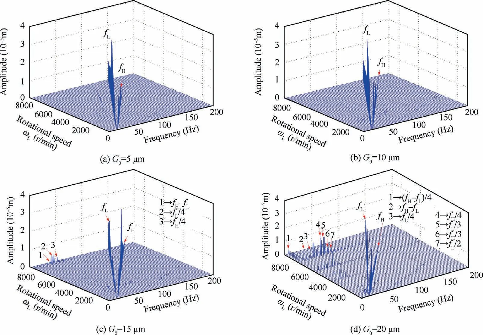
Fig. 24 Spectrum cascades under different ball bearing clearances with SFD.

Fig. 25 Vibration responses of disk 1 under four bearing clearances at ωL=1860 r/min without SFD.

Fig. 26 Vibration responses of disk 1 under four bearing clearances at ωL=6420 r/min without SFD.

Fig. 27 Vibration responses of disk 1 under four bearing clearances at ωL=1860 r/min with SFD.

Fig. 28 Vibration responses of disk 1 under four bearing clearances at ωL=5100 r/min with SFD.
Two fixed speed conditions are selected to analyze the vibration response of disk 1 in detail. The results are shown in Figs. 25-28. Fig. 25 shows that with the increase of bearing clearance, the vibration amplitude of disk 1 increases at the first resonance speed. Nevertheless, when the clearance of ball bearing is too large, the nonlinearity of the ball bearing force strengthens, resulting in the trajectory of disk 1 axis becomes very chaotic and the spectrum becomes continuous. When the rotational speed ωL=6420 r/min,the rotor orbit displacements are larger at the small bearing clearance G0=5 μm and G0=10 μm, while at the large ball bearing clearance G0=15 μm and G0=20 μm,the trajectory displacements become smaller,which indicates the amplitude jump phenomenon has happened according to Fig. 22, see Fig. 26.
The regularity of disk 1 amplitude variation is similar to that of the system without SFD, the main difference is the quasi-periodic motion disappears as the SFD is incorporated as shown in Fig. 27 and Fig. 28.
3.3. Effects of centralizing spring stiffness of SFD
Centralizing spring stiffness is one of the key parameters affecting the dynamics characteristics of the rotor system with SFD.The center spring of the damper is used to simulate elastic support, such as squirrel cage elastic support. The numerical calculations are carried out to analyze the effects of centralizing spring stiffness Kaon the system dynamic characteristics in this section. The amplitude-frequency curves under four different stiffness are exhibited in Fig. 29.
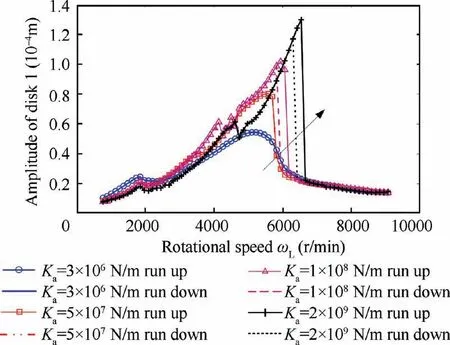
Fig.29 Amplitude-frequency responses of disk 1 under different centralizing spring stiffness.
When the values of the centralizing spring stiffness Kais small, such as the Ka=3×10⁶N/m, the damping effect of SFD restricts the inherent hard characteristics of ball bearing,so the amplitude jump phenomenon does not occur. As the centralizing spring stiffness becomes larger, the amplitude jump phenomenon becomes more and more distinct and the resonant peak shifts to right.The reason for the resonant peak shift is that the enhanced centralizing spring restrains the displacement of the outer ring of ball bearing, and this will weaken the damping effect of the oil-film force. Because the centralizing spring is in series connection with the ball bearing,the series stiffness will also increase.Thus,the critical speed of the system changes and the second-order resonant peaks shift to the right.In addition,resonance hysteresis begins to appear.It is worth noting that the amplitude of the first-order resonant peak reduces slightly with the increase of the centralizing spring stiffness.The change of centralizing spring stiffness will affect the stability of the system.
The effects of centralizing spring stiffness on the spectrum cascades of the system are shown in Fig.30.With the increase of centralizing spring stiffness, more and more combined frequencies and even fractional frequencies begin to appear. It can also be seen that the resonance rotational speed of amplitude jump (the red line) increases gradually.
Choosing the conditions of first-order critical speed 1860 r/min,the second-order critical speed 4380 r/min and the 6060 r/min (in the vicinity of the jumping speed) for specific analysis,the system vibration responses under four spring stiffness are shown in Figs. 31-33. The vibration amplitude of disk 1 slightly decreases with the increase of spring stiffness at the first-order critical speed, while the second-order resonance is the opposite (see Fig. 31 and Fig. 32). The rotor orbits and waveforms are irregular and aperiodic when Ka=1×10⁸N/m at ωL=4380 r/min, this shows that unreasonable damper parameters can introduce strong nonlinearities into the system.As shown in Fig 33,the amplitude jump of disk 1 has occurred when Ka=3×10⁶N/m or Ka=5×10⁷N/m,so the amplitude of the rotor orbit is small. The trajectory circle is relatively large for the other two large spring stiffness,which indicates that the jump phenomenon of disk 1 has not occurred according to Fig. 29.
3.4. Effects of oil film clearance of SFD
In practical engineering, because the radius of the damper always fits with the bearing, it can’t be changed arbitrarily.Therefore, the main parameters affecting the damping characteristics of SFD are damper length, oil film clearance, centralizing spring stiffness, and eccentricity. In this subsection, the influence of oil film clearance on the damping performance of the squeeze film damper is analyzed. The amplitudefrequency curves effected by SFD with oil film clearance of 0.07 mm, 0.08 mm, 0.09 mm, and 0.1 mm are exhibited in Fig. 34.
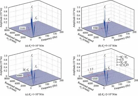
Fig. 30 Spectrum cascades under four different spring stiffness.

Fig. 31 Vibration responses of disk 1 under different centralizing spring stiffness at ωL=1860 r/min.

Fig. 32 Vibration responses of disk 1 under different centralizing spring stiffness at ωL=4380 r/min.
According to the Eq. (12), because of the decrease of oil film clearance, the increase of oil film pressure, the damping force acting on the bearing outer ring increases, which increases the oil film damping at the support, so the vibration reduction effect is enhanced. From Fig. 34, it can be seen clearly that the amplitude of the second-order resonance peak decreases gradually with the decrease of the oil film gap, but the position of the resonance peak is unchanged. The second-order vibration amplitude is reduced from 5.4×10⁻⁵m to 3.8×10⁻⁵m, about 30%. It is worth noting that the amplitude of the first-order resonance peak slightly increases with the decrease of oil film clearance while the vibration amplitude at other speeds is almost unaffected.

Fig. 33 Vibration responses of disk 1 under different centralizing spring stiffness at ωL=6060 r/min.
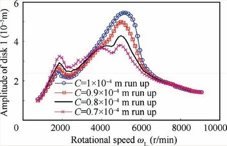
Fig.34 Amplitude-frequency responses of disk 1 under different oil film clearance.
Figs. 35-36 shows the detailed vibration response of inner rotor disc 1 at 1860 r/min and 4980 r/min. The rotor orbits and time domain waveforms show the amplitude changes at two resonant speeds, the vibration characteristics are similar in general. In the frequency spectrum, the inner and outer rotor rotational frequencies are dominant, and the combined frequency is weak.
4. Conclusions
In this paper,a dynamic model of a reduced dual rotor system supported by rolling bearing with a squeeze film damper is developed using the finite element method.Based on the developed model, the dynamical characteristics of a dual rotor system with SFD or without SFD are contrastively analyzed.The effects of center spring stiffness and oil film clearance of squeeze film damper on vibration reduction of dual rotor system are analyzed. Some conclusions can be summarized as follows:
(1)Because of the effect of the time-varying stiffness of ball bearing,the amplitude jump phenomenon occurs.For the system without SFD, the jump amplitude increases with the increase of mass unbalance,and the jump frequency increases.When the ball bearing clearance becomes larger, the vibration amplitude increases, and the corresponding resonant frequency decreases apparently, the resonance hysteresis phenomena for the frequency response curves will enhance.

Fig. 35 Vibration responses of disk 1 under different oil film clearance at ωL=1860 r/min.

Fig. 36 Vibration responses of disk 1 under different oil film clearance at ωL=4980 r/min
(2) For the dual rotor system with SFD, smaller mass unbalances, centralizing spring stiffness, the ball bearing clearances G0and oil film clearance contribute to the vibration reduction of the system and improve the system stability.These parameters(except oil film clearance)will affect the shift of resonance peak.By adjusting these parameters,the dynamic characteristics of the system crossing the critical speed will be changed. The SFD with reasonable parameters has a good damping effect and can suppress the amplitude jump phenomenon. With the centralizing spring stiffness increases, the vibration damping performance of SFD declines and resonant peak increases. In general, the squeeze film damper can suppress the dynamic instability and reduce the vibration by more than 60%.
The main contribution of this paper is the comparative analysis of squeeze film damper with appropriate parameters for suppressing amplitude jump phenomenon in the steadystate unbalanced response of the dual rotor system. Furthermore, the influence of several key parameters for minimizing the vibration of the dual rotor system is discussed throughout the operating range.The analysis of this paper is significant for the estimate and analysis of the vibration response of the dualrotor system affected by inherent support nonlinearity.
In future works, further experiments will be carried out to verify the theoretical results in this paper,the influence of other parameters of SFD on the system’s vibration responses will be evaluated.
Declaration of Competing Interest
The authors declare that they have no known competing financial interests or personal relationships that could have appeared to influence the work reported in this paper.
Acknowledgments
This project is supported by the National Natural Science Foundation of China (Nos. 11772089, 11972112), the Fundamental Research Funds for the Central Universities, China(Nos. N170308028, N2003014 and N180708009), and LiaoNing Revitalization Talents Program, China (Nos.XLYC1807008).
 CHINESE JOURNAL OF AERONAUTICS2021年10期
- CHINESE JOURNAL OF AERONAUTICS的其它文章
- Direct dynamic-simulation approach to trajectory optimization
- A strong robustness open-circuit fault diagnosis strategy for novel fault-tolerant electric drive system based on d-q-axis current signal
- Ground maneuver for front-wheel drive aircraft via deep reinforcement learning
- Numerical simulation of a UAV impacting engine fan blades
- Recent advances in precision measurement &pointing control of spacecraft
- Transition characteristics for a small tail-sitter unmanned aerial vehicle
