Numerical simulation of a UAV impacting engine fan blades
Jingyu YU, Bingjin LI, Jun LIU,*, Nin HOU, Yinghun ZHANG,Yfeng WANG, Yulong LI
a School of Aeronautics, Northwestern Polytechnical University, Xi’an 710072, China
b Science and Technology on Reactor System Design Technology Laboratory, Nuclear Power Institute of China,Chengdu 610213, China
c Shanghai Aircraft Airworthiness Certification Center of CAAC, Shanghai 200335, China
d China Aircraft Strength Research Institute, Xi’an 710065, China
KEYWORDS Airworthiness;Bird impact;Engine fan blade;Explicit dynamics;UAV
Abstract A 3D digital model of a small Unmanned Aerial Vehicle(UAV)is obtained by using the method of scanning reverse modeling and joint mapping. A numerical simulation of a small UAV strikes on rotary engine blades,presented in this paper,was performed with a Transient Nonlinear Finite Element code PAM-CRASH software.A test of motor strike on plate was developed and the dynamic response of the plate were obtained to validate the numerical simulation method of a UAV strike on blades. Based on this, dynamic damage response caused by UAV on the engine blades were studied. It is indicated that the impact process between the UAV and a single blade can be divided into two typical stages:cutting and impact.Cutting mainly leads to the failure of the leading edge material,and impact mainly leads to the plastic deformation of the blade.At the same time,it is compared with the damage impacted by bird with the same mass.For the same mass of bird and UAV, the damage caused by UAV striking fan blade is more serious, and 1.345 kg UAV striking fan blade of typical civil aviation engine is enough to cause damage to flight safety.
1. Introduction
In recent years, there has been a rapid growth in incidents of Unmanned Aerial Vehicle(UAV)disrupting flights.According to the statistical report data of European Aviation Safety Agency (EASA), there were nearly 1000 dangerous approach incidents of UAVs and aircrafts in Europe from 2010 to 2016, which resulted in different degrees of aircraft structure damage and economic loss1; According to British statistics,there were 29 dangerous approaching incidents between UAVs and aircraft in 2015. At the most dangerous time, an airbus A319 was just a few meters from colliding with a UAV. By 2017, there were 92 similar dangerous approaching incidents.2In the first 11 months of 2018, there were 120 incidents of UAV dangerously approaching manned aircraft.3According to the Federal Aviation Administration (FAA) statistics report, the number of accidents caused by UAV and aircraft collision or nearly collision has increased year by year since 2014, and as of August 2016, the number of accidents has reached 650.It is reported that on April 17,2016,a British Airways A320 carrying 132 passengers was suspected of being hit by a UAV when it landed,making it the first reported incident of suspected UAV hitting an airliner in the world.4In the afternoon of January 5, 2017, a Boeing 737 of Mozambique Airlines with 86 people on board was suspected of colliding with the UAV when landing, causing multiple long wounds on the right side of the nose cone of the aircraft.5
UAV impact on civil aircraft belongs to the category of foreign object debris impact, which is a highly nonlinear impact dynamics problem, involving many disciplines such as Aviation, Mechanics, Materials, and so on. At present, the researches on FOD impact at home and abroad are mainly focused on bird impact, hail impact and other issues, and relatively mature research results have been achieved,which provide relatively mature technical means for the airworthiness verification.
There are few researches on UAV collision,which is still in its infancy. However, there is a great similarity between UAV impact and bird impact.Both UAV and bird impact belong to the millisecond impact dynamics problem, and the impact location is roughly the same, including windshield, wing leading edge, flat tail, vertical tail and engine, etc. Therefore, we can use the research ideas of bird impacting to study the UAV impact.
The Federal Aviation Administration (FAA) has systematically studied the impact of rotor configuration and fixed wing configuration UAVs on civil airliners and commercial aircraft respectively.6–8FAA establishes the CAD model of UAV through reverse engineering and the finite element model of UAV by building block method, as shown in Fig. 1. The reliability of the finite element model is verified by the part level plate impact test. Based on the finite element model of UAV,the finite element model of UAV collision with aircraft is established and simulated. In addition, the Federal Aviation Administration (FAA) drafted relevant regulations on UAV control,9and issued a series of research reports on UAV impact in 2017. The fourth part of the report8conducted numerical simulation and damage assessment on UAV impact engine. At the same time, the European Aviation Safety Agency (EASA), British Civil Aviation Administration and other relevant agencies have also set up research teams to assess risk of UAV collision with aircraft.10,11
The team of Professor Ian Horsfall from Cranfield University conducted relevant experiments on UAV collision with aircraft.12Based on the research idea of using dead chicken instead of live bird in bird impact test, they made a projectile similar to UAV in volume, mass and mechanical properties,and specially made an air gun with a barrel diameter of 4 inches and a length of 10 inches for launching the projectile.The test results show that the simulated missile can’t break through the windshield, but can tear the radome. The University of Dayton in the United States conducted the test of UAV impacting the wing.13A DJI Phantom 2 UAV weighing 2.1 pounds (about 0.95 kg) and a similar weight bird were hit at the speed of 238 miles per hour (106 m/s) on the wing of the Mooney M20 aircraft. The test results show that the UAV does not break when it impacts, but directly tears the leading edge of the wing into the interior of the wing structure, and damages the main wing beam, causing serious damage to the aircraft structure. The team of Javid bayandor, Professor of crash lab, Virginia Tech University, has done a lot of simulation work on the intake aero-engine of UAV.14,15They first compared the effects of an equivalent mass (2.5 kg)UAV and a bird inhaled engine. The simulation results show that under the condition of equal mass, the UAV inhaled engine can cause greater impact force than the bird inhaled engine, resulting in more serious blade damage. Because bird impact belongs to soft impact, while UAV contains rigid components such as motor and battery,which can cause bigger damage.
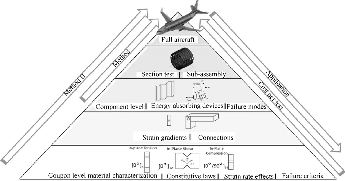
Fig. 1 Schematic diagram of building block method.
In 2017, Shanghai Aircraft Airworthiness Certification Center,together with relevant research institutions and universities, carried out the world’s first test of UAV collision with real nose structure(including windshield)and tail.The selected consumer DJI UAV weighted a range of 0.3 kg to 3.33 kg.The rocket sled was used to accelerate the nose and tail, and the impact velocity was from 120 m/s to 150 m/s. The results of the impact windshield test show that the UAV can smash the outer glass of the windshield, but the inner glass remains intact. The impact of the flat tail test show that the UAV can penetrate the skin and cause damage to the internal structures.16Liu et al.17conducted a comparative study on the numerical simulation of the impact of small UAV and bird body on the aircraft windshield. The calculation results show that the small UAV is more destructive than bird body. Wu et al.18used ABAQUS to establish a dynamic finite element model for the impact of UAV on civil aircraft, and studied the consequences of the impact of UAV on key parts of civil aircraft (such as windshield, wing, engine blade, etc.). Wang et al.19carried out the numerical simulation of the impact of the UAV and the bird on the wing. The results show that the impact of the UAV on the aircraft is more destructive than that of the bird.
At present, there are few reports on the damage of the engine blades impacted by UAV.This paper aims at the potential risk of UAV impacting aircraft engines. Firstly, a 3D digital model of small UAV is obtained by using the method of scanning reverse modeling and joint mapping.Then,a numerical simulation model of the impact between a small UAV and a fan blade of a typical engine is established,and the rationality of the UAV motor model is verified by experiments. Based on this,the damage of the fan blade impacted by UAV is studied, and compared with the impact damage of the same mass bird body. The research results have some reference significance for the revision of airworthiness standard of small UAV and the exploration of test standard of small UAV impacting engine structure.
2. UAV model
2.1. UAV 3D model
The research object of this paper is a small consumption four rotor UAV phantom 4,which has a total weight of 1.35 kg and an overall size of 289.5 mm×289.5 mm×196 mm, as shown in Fig. 2 (a). Its main structure includes the fuselage shell,the internal circuit structure, motor, battery, camera platform and propeller. The three-dimensional digital model of phantom 4 UAV is established by scanning reverse modeling combined with mapping. For the regular structure of the internal circuit structure, motor, battery, camera platform, etc. The electronic caliper, electronic protractor and other instruments are directly used for mapping, and the three-dimensional model is built in CATIA software. Fig. 2 (b) shows the whole structure of UAV. The fuselage and propeller have complex curved surface shape. This structure uses the scanning inverse modeling method to get the three-dimensional model. The main method is to take the UAV component as the prototype,obtain the digitized 3D point cloud model data of the UAV component through the three-dimensional scanning. Based on the cloud data, using the reverse engineering software,according to the steps of point construction surface and surface construction body,create CAD three Dimension module,as shown in Fig. 2 (c).
The circuit board inside the UAV fuselage is light in weight,the mechanical properties of the materials are weak, and it is difficult to cause damage to the engine blades during the impact. Therefore, in this paper, the internal circuit board structure of the fuselage is simplified as a homogeneous cuboid with approximate geometric appearance size. The comparison between the CAD model of the internal circuit structure and the real object is shown in Fig.2(d).The motor is mainly composed of aluminum alloy, steel, copper and other metal materials, which is one of the UAV components with high rigidity.The motor is located at the outermost side of the overall structure of the UAV, which is the first part to cause great damage to the engine blades during the impact. Therefore, this paper carries on the fine modeling to the motor.The motor is mainly divided into four parts:stator,rotor,shaft and base.The structure of stator and copper coil is complex,which is simplified to a simple geometric entity structure during modeling, and the rest parts are modeled by actual size mapping, as shown in Fig. 2 (e). The mass and volume of the UAV battery is large,which will cause serious damage to the structure in the impact.The battery mainly includes the plastic shell and four internal electric cells. In this paper, the plastic shell is simplified as a rectangular surface, and the electric core is simplified as a cuboid with the same geometric appearance as the real object,as shown in Fig. 2 (f). The camera platform includes metal materials with larger rigidity. The camera platform and the camera head can be simplified into uniform mass blocks similar to the actual product geometry.The 3D model of the camera platform is established as shown in Fig. 2 (g).
2.2. UAV mesh generation
2.2.1. Mesh generation
The fuselage, propeller and battery cover components of the phantom 4 UAV are basically thin walled structures. Therefore, two-dimensional shell elements are used to mesh these structures.The size of the element is about 3 mm,and the mesh is refined at the position with complex geometry. The other parts, such as motor, battery cell and camera pan/tilt, have large mass and rigidity,and are solid structure.Therefore,hexahedral elements are used to mesh these structures,and the size of the element is about 1.5 mm. In order to ensure the quality of mesh generation, the surface cutting, solid cutting, fusion and other operations are carried out for the parts with complex geometric features.In this paper,the UAV structure is divided into 23668 shell elements and 47832 individual elements, as shown in Fig. 3.
2.2.2. Verification of mesh size independence
Mesh density is an important factor affecting the accuracy of numerical results.Generally,with the increase of mesh density,the accuracy of numerical results will be improved, but the computer storage space and calculation time will also be greatly improved, and the calculation efficiency will be reduced. Therefore, the balance between calculation accuracy and efficiency should be considered in mesh generation, and it is necessary to verify the mesh size independence.Mesh independence means that when the number of meshes in the finite element model reaches a certain order of magnitude,the calculation results will not change significantly with the increase of the number of elements.
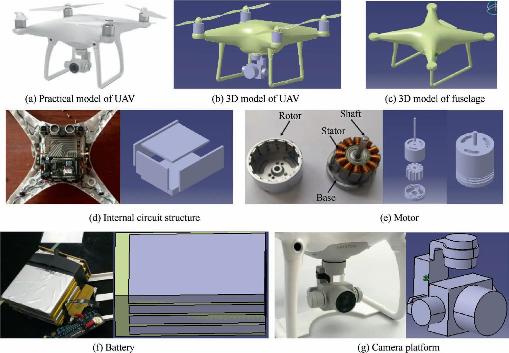
Fig. 2 Small UAV and 3D model.
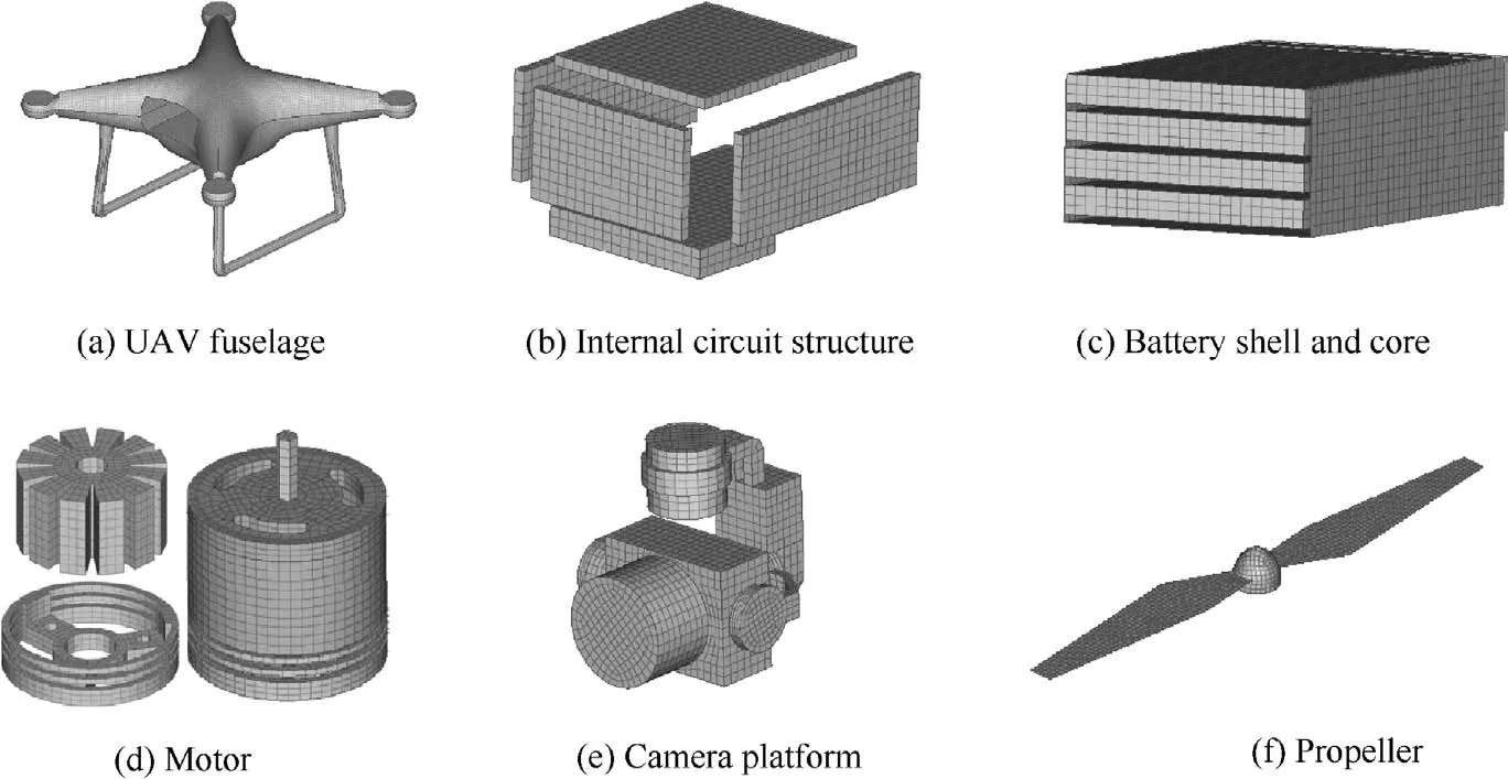
Fig. 3 Mesh of UAV.
The UAV mainly meshed by the body and shell element.In order to verify the independence of the mesh size, a numerical simulation model of the motor impact plate is established, in which the motor is divided into the body element and the plate is divided into the shell element,as shown in Fig.4.In the first group, the motor meshed element size is 1.5 mm, the plate meshed element size is 3 mm; in the second group, the motor meshed size is 1 mm,the plate meshed size is 1 mm;in the third group,the motor meshed size is 0.5 mm,the plate meshed size is 0.7 mm.
The calculated results are shown in Fig. 5. The displacement curves of three groups for the center points on plate with different meshed element size are highly coincidently aligned.Therefore, in order to save computer storage space, reduce computing time and improve computing efficiency. The mesh size of the UAV structure is determined to be 1.5 mm, and the shell mesh size is determined to be 3 mm.
2.3. UAV material model
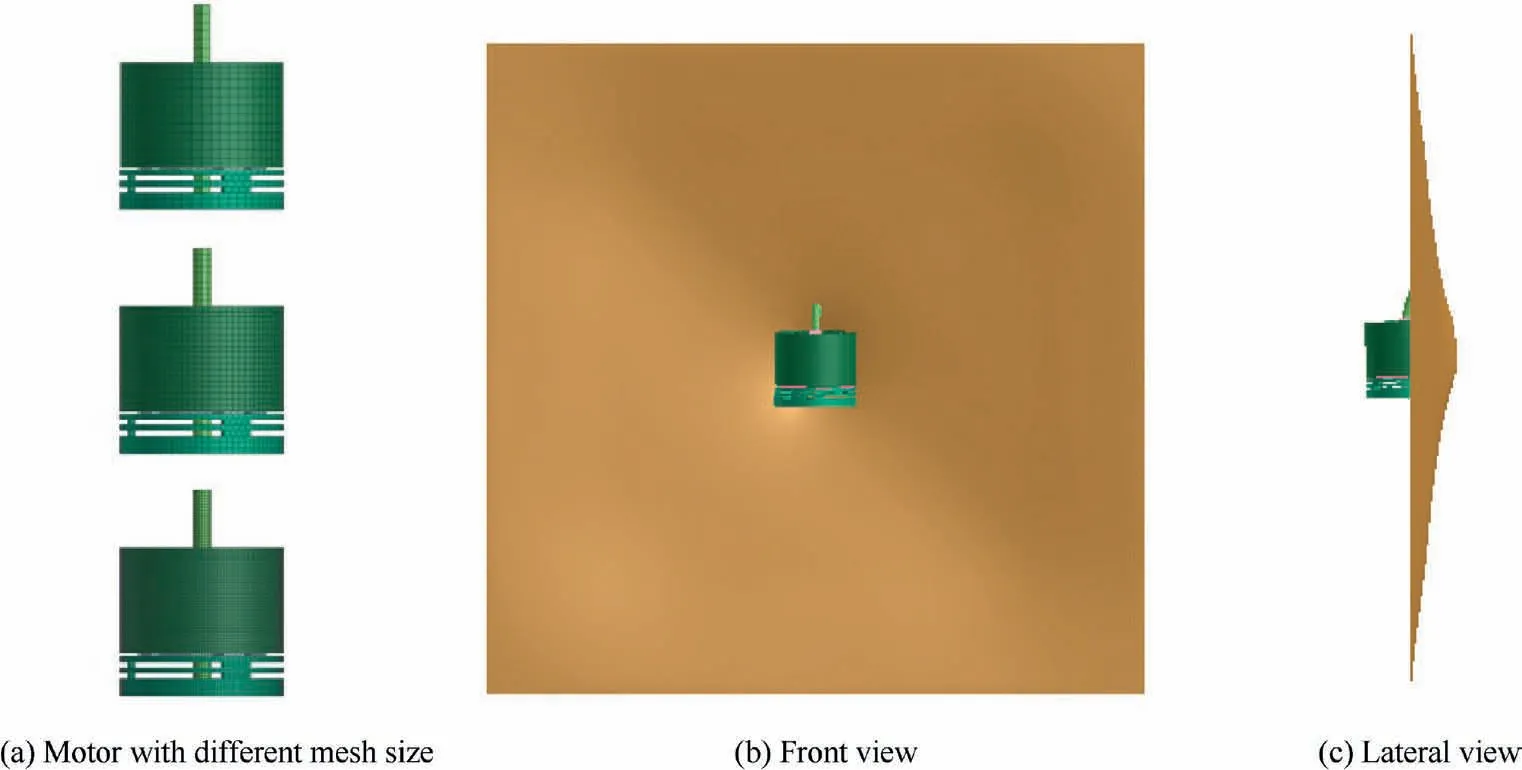
Fig. 4 Deformation of plate impacted by motor with different mesh sizes.
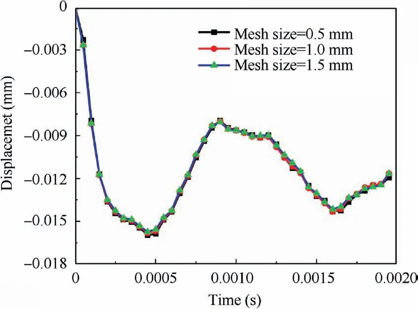
Fig. 5 Comparison of displacement of plate center point with different mesh sizes.
The UAV structure uses a variety of materials,including polycarbonate,a variety of metal materials such as aluminum alloy and steel. The internal structural materials of the motor and camera pan/tilt are complex, the mechanical properties of the battery cell materials are special, and the mechanical properties of the internal circuit structures are difficult to determine.
When the UAV strikes the aircraft structure,the parts with small mass and weak rigidity such as fuselage, propeller and battery shell are difficult to cause serious damage to the aircraft structure.The fuselage,propeller,battery shell and other structural materials are similar to polycarbonate hard plastic.For numerical simulation, polycarbonate adopts the elastic–plastic model of ideal plasticity,and the material failure is controlled by strain failure. The failure strain is set to 0.2. The mechanical property parameters of polycarbonate can refer to the material parameters7in FAA related reports and literatures, as shown in Table 1. In the table, ρ is the density of thematerial, E is Young’s modulus, v is Poisson’s ratio, σsis the yield stress, εfis the fracture strain.

Table 1 Mechanical properties of polycarbonate.
The motor components are mainly composed of stator,rotor and base. The stator material can be equivalent to 45#steel, and the rotor and base material is 6061-T6 aluminum alloy. The flow stress and strain rate effects of the two metals can be simulated by Johnson Cook constitutive model. The expression of JC constitutive model is:

In the above expression, σ is Mises equivalent stress, ε is equivalent plastic strain, ˙ε is equivalent plastic strain rate, T*is temperature parameter.A,B,n,C,m are the material property parameters that need to be determined. In the process of UAV impact, temperature effect is not considered, so, only the first two items of JC constitutive model are used in this paper, and the specific parameters are shown in Table 2.
The test on mechanical performance of battery cell is still a difficulty in the industry. The cell is composed of cathode,anode and diaphragm. During the finite element modeling,the micro model of each component can be established separately, or the overall homogeneous model can be established based on the equivalent idea.20Sahraei et al.21,22used homogeneous foam materials to simulate the compressive mechanical behavior of bagged batteries. The simulation results are in good agreement with the experimental data. Therefore, referring to the research results of Sahraei et al., the whole homogeneous finite element model of battery core is established.The foam material model is equivalent, and the specific model parameters are shown in Table 3.
For UAV camera platform and the internal circuit structure are complex, the three-dimensional model is simplified,and its material property can be homogenized and equivalent.The camera platform structure material property is equivalent to 6061-T6 aluminum alloy, and the internal circuit structure material property is equivalent to elastomer.Adjust the density of the equivalent material model of the camera platform and the internal circuit structure to ensure that the quality and center of gravity of the model are consistent with the actual situation.

Table 2 Johnson Cook constitutive model parameters of 45# steel and 6061-T6.

Table 3 Mechanical property parameters of battery cell.
2.4. Numerical model of motor and verification
2.4.1. Test method of plate impacted by motor
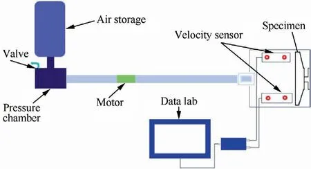
Fig. 6 Air gun test system.
The air gun system is used in the test, which is mainly used to accelerate the motor. The air gun system is mainly composed of air tank, air chamber and gun tube, as shown in Fig. 6.Its working principle is that before launching, the sabot and the projectile are first loaded into the barrel. Then charge the air chamber through the air compressor, monitor the pressure value in the air tank through the pressure gauge on the air tank, and stop charging when the specified air pressure is reached. When launching, open the airtight valve of the air chamber, the high-pressure air in the air tank will push the sabot and projectile in the gun tube to accelerate along the gun tube. At the exit of the gun tube, there is a device which can block the movement of the sabot, and so, the sabot and projectile are separated.After the sabot and projectile are separated,laser sensor is used to measure the impact speed of the projectile. The actual test equipment is shown in Fig. 7(a).
The mass of the motor is light and the geometrical shape is irregular. When accelerated in the air gun tube, it will rotate around the axis of the gun tube, which has a great influence on the repeatability of the test results. A slider is added in the air gun barrel to prevent the motor from rotating around the gun barrel axis, as shown in Fig. 7 (b). In order to ensure the impact posture of the motor, the sabot suitable for motor impact is processed as shown in Fig. 7 (c).
The mass of UAV motor is about 51.5 g,the main body is a Ø26 mm×28.2 mm cylinder, and the top is a Ø3 mm×10 mm motor bearing,as shown in Fig.8.The target plate is 2024-T3 aluminum alloy with a thickness of 1.6 mm and a size of 300 mm×300 mm. A set of clamps which can impose circular boundary conditions on the flat plate is designed in the experiment, as shown in Fig. 9.
During the test, dynamic strain gauge was pasted on the back of the impact point of the target plate to measure the strain time history response of the target plate in the impacting process. Strain gauge is likely to fail under high-speed impact load, resulting in the data loss. In order to obtain complete dynamic response data of target plate deformation as much as possible, a group of strain gauges of the same specification are arranged at four different positions from the center of the plate, as shown in Fig. 10. Among them, No.1 and No.2 are along the vertical direction, with the distance from the center of the circle of 25 mm and 85 mm respectively. The distance between No.3 and No.4 along the horizontal direction and the center of the circle is 25 mm and 85 mm respectively.
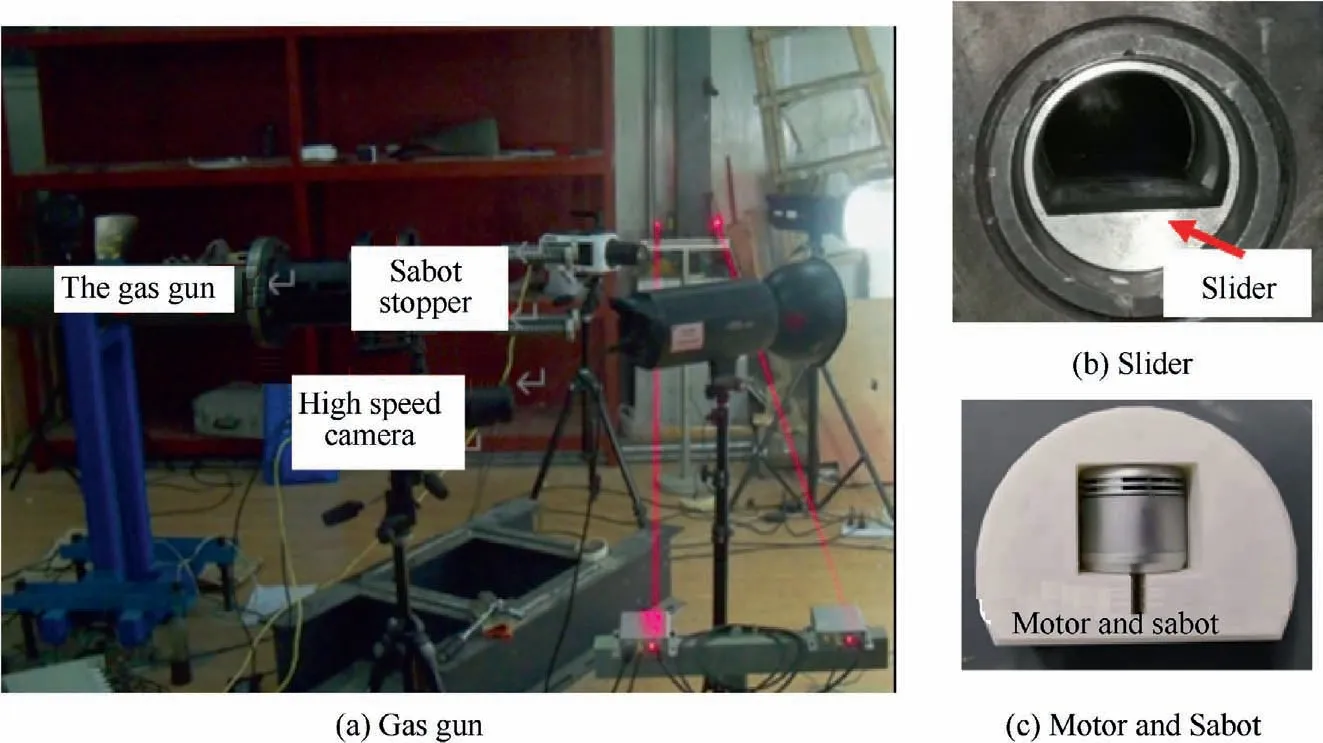
Fig. 7 Air gun test device.
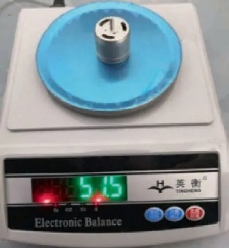
Fig. 8 UAV motor.
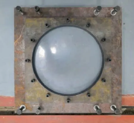
Fig. 9 Test target board.
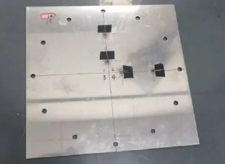
Fig. 10 Location of strain gauge.
2.4.2. Test result
In the test, the impact speed of the motor is recorded by the laser velocimeter, and the impact speed and posture of the motor are recorded by the high-speed camera.The internal slider of the gas gun barrel limits the axial rotation of the motor around the gun barrel when accelerating, so the angle in this direction can be ignored, only the pitch angle of the bullet is considered. The definition of pitch angle in the process of motor impact is shown in Fig. 11. During the measurement,the pixel coordinates of point A in the upper right corner of the motor (x1, y1) and point B in the lower right corner (x2,y2) are read respectively. The pitch angle of the bullet can be obtained by the following formula:

In this paper, an impact test is carried out. The laser velocimeter records that the impact speed of the motor is 96 m/s, and the pitch angle is 33° through the measurement of high-speed camera pictures.The high-speed camera records the process of the motor breaking down the plate. Fig. 12 shows calculation model .At 0.15 ms and 0.20 ms, the interaction between the motor and the plate is shown in Fig. 13 (a).The simulation result is presented in Fig. 13 (b).
When the motor strikes the aluminum plate at high speed,the strain gauge is easy to be pulled off,and the wire connected with the strain gauge is also easy to be pulled off, resulting in the lack of strain data. Especially in position 2 and 3, due to the close distance from the impact point,the plate deforms violently,and the strain gauge will be pulled off soon,resulting in the lack of strain data.In this test,only the strain data of position 1 and 4 are tested, as shown in Fig. 14. Because the positions of 1 and 4 are symmetrical relative to the impact position,the strain time history response curve is basically the same.
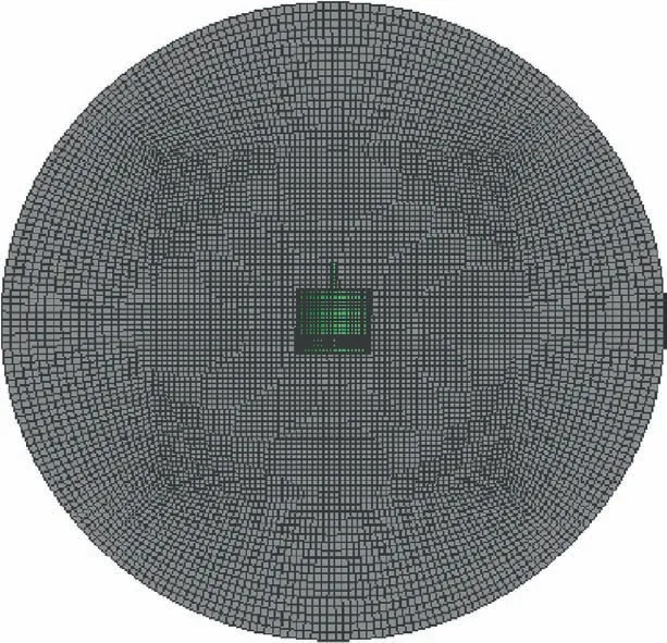
Fig. 12 Numerical simulation model of motor impact on flat plate.
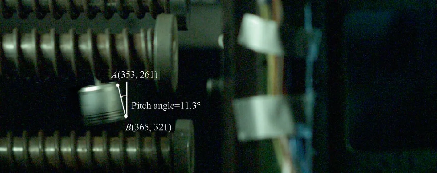
Fig. 11 Definition of pitch angle during impact.
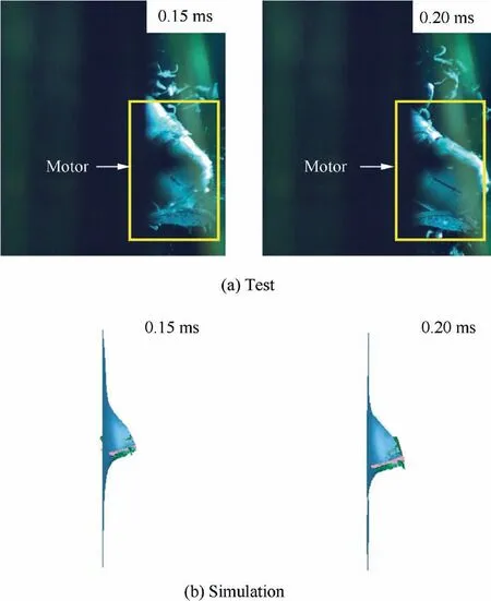
Fig. 13 Comparison for simulation and test of breakdown process of motor on flat plate.
The damage morphology of aluminum plate after impact is shown in Fig. 15. The impact pitch angle is large, and the motor breaks through the aluminum plate and causes triangle opening and large crack on the aluminum plate.The morphology of the motor after impact is as shown in Fig. 15(c). After impact,the motor still maintains its basic shape,and the direct impact surface of the motor has large deformation.The deformation of the hollow base of the motor is large, which indicates that its impact resistance is weak. In addition, the propeller shaft of the motor is obviously bent,but not broken.
2.4.3. Numerical simulation and verification
The finite element simulation model of motor impacting with flat plate is established. In the test, the flat plate is equivalent to the circular fixed boundary condition, so the simulation model simplifies the flat plate to a circular flat plate with a diameter of 230 mm,and applies the fixed boundary condition around the circular plate. The plate material is 2024-T3 aluminum alloy, Johnson-cook constitutive model is adopted,and the specific parameters are shown in Table 4. The quadrilateral shell element is used to mesh the plate.The mesh size is set to 2 mm, and the impact area mesh is divided into regular quadrilateral.The plate is divided into 9006 quadrilateral shell elements.According to the motor impact plate test conditions,the calculation model is established as shown in Fig. 12.
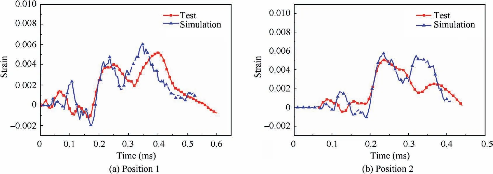
Fig. 14 Comparison of strain time history for test and simulation.

Fig. 15 Comparison on damage morphology of plate for simulation and test.

Table 4 Johnson Cook constitutive model parameters of 2024-T3 aluminum alloy.
The results of high-speed camera show that when t=0.15 ms, the motor breaks through the plate, and when t=0.20 ms, the motor is still stuck on the plate, showing a critical state of breakdown. The comparison between the calculation results and the test high-speed video recording results is shown in Fig. 13. After the motor penetrates the flat plate,the calculation result of the residual speed of the motor is zero,indicating that the motor is in a critical breakdown state,which is consistent with the test results.
The comparison between the calculation results of plate strain response and the test results is shown in Fig.14.The test results at positions 1 and 4 show two obvious peaks, and the calculation results also show two obvious peaks. The peak value of simulation at position 1 is about 19% larger than the test result, and the overall fluctuation is small. The peak value of simulation at position 4 is about 14% larger than the test result. The overall trend of simulation results at positions 1 and 4 is in good agreement with the test results.
As shown in Fig. 15, the simulation results on the damage morphology of the plate impacted by the motor are compared with the test results. The plates are all broken down and have similar triangular notches, and the dimensions of the triangular notches are basically the same. The test results show that the deformation of motor base and propeller shaft is large,which is basically consistent with the predicted results. The simulation results of the above-mentioned high-speed camera,strain and damage morphology are in good agreement with the test results,which shows that the numerical simulation method in this paper is reasonable.
3. Numerical simulation model
3.1. Geometry and mesh model
In this paper, the fan blade is a typical wide-chord fan blade of high bypass ratio turbofan engine. The blade airfoil is shown in Fig. 16 (a). The thickness of the profile airfoil center is the largest, and the thickness gradually decreases to both sides, and changes along the span wise direction. The blade is composed of an external panel and an internal core plate, wherein the thickness of the external panel is the largest at the blade root and the smallest at the blade tip. The inner part is hollow Warren structure, the thickness of core plate is 0.5 mm, and the range of Warren number is 10–20.Considering the stress wave propagation in the direction of blade thickness, the hexahedral element is used to mesh the blade. Each blade is meshed into 56,250 elements, including 46,875 elements for the external panel and 9375 elements for the internal core panel. The joint between the core plate Warren structure and the inner wall of the blade is treated as a joint.
The deformation of hub is smaller than that of blade,so the geometry of hub is simplified as cylinder surface,quadrilateral shell element is used to mesh and set as rigid body,ignoring the deformation of hub.The blade root and hub are connected by a common node.The diameter of the whole stage fan is 1.95 m and consists of 18 blades. The numerical model is shown in Fig. 16 (b).
3.2. Numerical simulation model
In this paper, the material of blade is Ti-6Al-4 V (TC4). The strain rate effect of TC4 must be considered because of the instantaneous impact load of UAV impact. Therefore,Johnson-Cook (JC) constitutive model related to strain rate is selected in this paper. The JC model parameters of TC4 material are determined through the mechanical properties test of the samples processed with the furnace material.The failure behavior of the material is determined by the equivalent failure strain εf, that is, when the equivalent strain of the element exceeds the failure strain of the material, the element is deleted and the parameter is measured by the test. The specific parameters of TC4 for JC constitutive model are shown in Table 5.

Fig. 16 Geometry and mesh model.

Table 5 Johnson Cook constitutive model parameters of TC4.
The structure of the UAV impact engine has not yet been included in the airworthiness standard of the aero engine, so the initial boundary conditions can be set according to the regulations on the air worthiness of engine absorbing birds(CCAR33.76) to facilitate the comparison with the bird strike damage under the same impact conditions. CCAR33.76 stipulates that the engine shall be stable at not less than 100% of takeoff power or thrust and the speed of the bird shall be 370 km/h (about 102 m/s). Therefore, this paper calculates the typical conditions of civil aircraft taking off with maximum thrust.The fan speed is set to 3500 rpm,and the impact speed between UAV and fan is set to 102 m/s.The interaction of the UAV with the blade may be modelled by the existing sliding interface algorithms available within PAM-CRASH.The most frequently used sliding interface types to relate this problem are type 34 in case the materials may be considered. The contact thickness should be representative of the half-thickness of the shell structure.In addition,the contact interaction between UAV and UAV,blade and blade were also defined in the simulation model.The entire numerical simulation model is shown in Fig. 17.
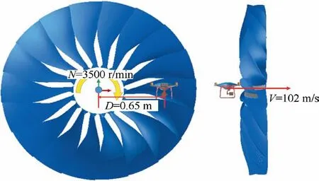
Fig.17 Numerical simulation model on aero engine impacted by UAV.
4. Results and discussion
4.1. Damage of engine blades impacted by UAV
Fig.18 shows the process of UAV impacting on the fan blades,and the impact time is about 4 ms. Fig. 19 is the impact force time curves of each blade at different times during UAV impacting on the fan blades. In the process of impact, the UAV contacts four blades(for the convenience of observation,the blades without impact are hidden in the figure). When the initial position is 0,at 0.8 ms, the leading edge of blade 1 contacts with the bottom of the UAV and starts to cut two arms;after about 0.2 ms, the cutting ends, and then the blade 1 is mainly impacted by two small motors, and the impact force curve also shows two peaks. Blade 2 was impacted by the largest mass part of UAV(including battery and part of fuselage),and the peak value of impact force curve (about 255 kN) was much higher than other blades. Blade 3 and blade 4 are cut with arm of UAV respectively, and then collide with a small motor, so the impact force curve has a peak value.
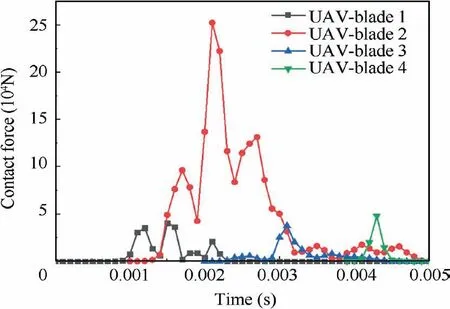
Fig. 19 Contact force vs time curves of the UAV impacting on different blades.
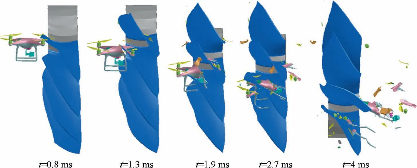
Fig. 18 Typical states of the UAV impacting on fan blades at different times.
Several typical states of blade 2 in the process of impact are extracted,as shown in Fig.20,and the collision mode between UAV and fan blade is studied in detail.It can be found that the leading edge of blade 2 is cut with the bottom bracket and the fuselage first, and the cutting is finished about 1 ms later. The residual UAV including battery collides with the blade basin of blade 2, and moves along the speed direction to the trailing edge of the blade. The whole impact time is about 3.7 ms.Therefore, the impact process between UAV and single blade can be divided into two typical stages: cutting and impact.the impact. Fig. 22 shows the kinetic energy changes of UAV typical components before and after impact. Combined with Fig. 18, it can be found that the structure of battery is basically intact before and after impact,although the fire probability is small,because it is accelerated by rotating blades during the impact process,the energy after the impact is increased,and the case is prone to be broken down and other consequences.
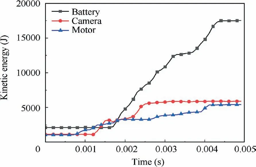
Fig. 22 Kinetic energy of typical components of UAV.
4.2. Damage of blades impacted by UAV compared with bird
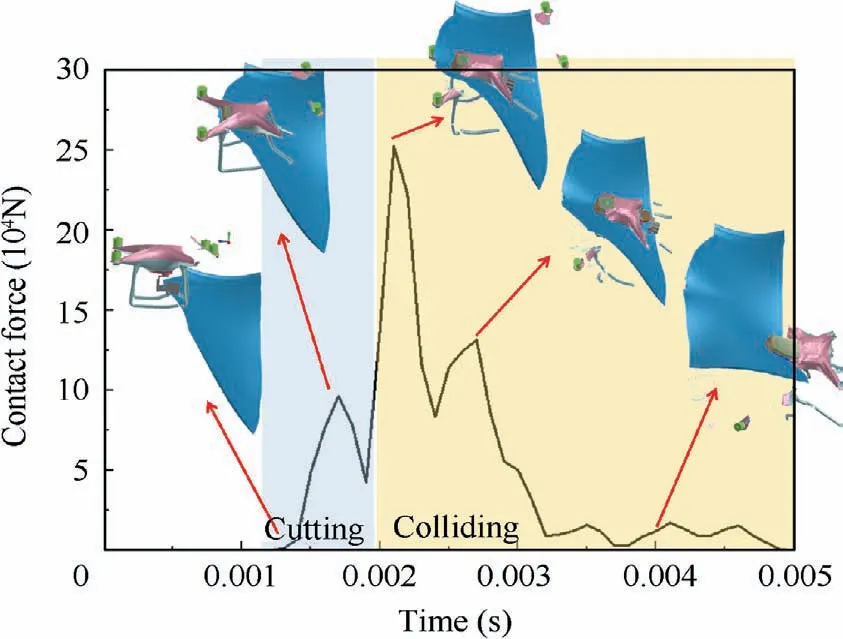
Fig. 20 Contact force vs time curve on blade 2 impacted by the UAV.
Fig.21 shows the deformation and damage of the fan blade after the impact. It can be seen that the damage of blade 2 is the most serious, the whole blade presents certain torsion and bending deformation,the back of blade presents Walloon plastic deformation due to bearing pressure stress,and there is a small amount of material failure at the leading edge of blade.Blade 1 and 4 present dents at the leading edge and the middle of blade basin due to small motor impact,but no material failure occurs,and the local plastic deformation is small,which is not enough to affect the engine thrust performance.
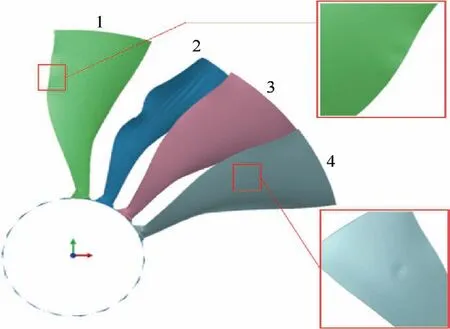
Fig. 21 Damage on fan blades impacted by UAV.
When the battery is impacted into the inside of engine structure, partial damage is more likely to cause sparks than complete damage, and partial damage is more likely to cause fire. Therefore, the fire probability can be roughly evaluated by observing the structural damage degree of battery after In order to further study the impact characteristics of UAV,the numerical simulation of bird strike fan blades with the same mass and speed was carried out, the impact damage of the UAV and the bird on the fan blade was compared. SPH method is the most commonly used in bird projectile modeling,because it can avoid the problem of mesh distortion when the structure is large deformation, and can better simulate the large deformation, breaking and flying of bird projectile in the process of bird impact.A bird strike numerical model must be able to simulate the interaction between bird–blade and blade–blade. The most frequently used sliding interface types to relate smooth particles to finite elements are type 34. The contact thickness should be representative of the particle radius,possibly augmented with the half-thickness of the shell structure.So the node to surface contact was used to model the interaction between the SPH particles and Lagrange elements.The hubs attached to the shaft were modelled as rigid body.The rigid body assumption implies that the deformation of the engine shaft and hubs are neglected during bird strike event. A Center of Gravity (COG) node is generated for hubs which is simulated by rigid body,and the displacement boundary conditions were defined on this node.The entire numerical simulation model of bird strike is shown in Fig. 23.
A 1.35 kg bird with a velocity of 102 m/s strike event against the engine fan blades with a rotary speed of 3500 r/min was simulated to observe the damage behavior of the system. The deformation and damage results of the simulation during and shortly after the impact are shown at various times in Fig. 24. The SPH bird model exhibited fluid-like behavior upon impact as material flowed and spread out across the blades. The soft bird body was separated into multiple portions due to slicing by several blades as a result of interaction between the bird and blades, with portions of it coming into direct impact with four blades.
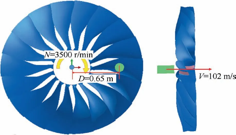
Fig.23 Numerical simulation model on aero engine impacted by bird.
The results show that the damage of fan blade is less after bird impact, as shown in Fig. 25. Only blade 2 has slight curling at the tip, and blades 1 and 3 have slight plastic deformation at the leading edge.Compared with the results of damage caused by UAV,although the same mass of bird projectile and UAV all collided with four blades,the impact damage of UAV is more serious.
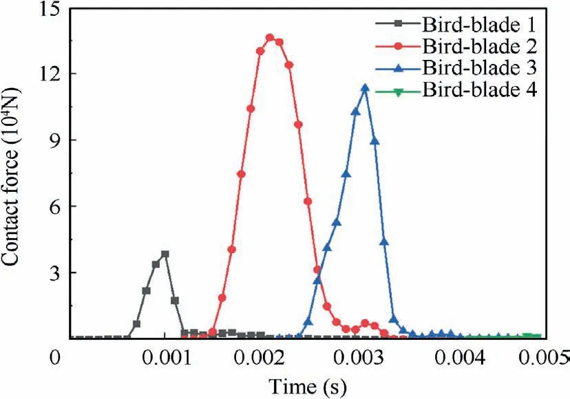
Fig. 26 Contact force vs time between bird and blade.
Fig. 26 shows the contact force curve of bird projectile impacting each blade. Combined with Fig. 25, it can be seen that the blade with the most severe damage under the two impact sources is blade 2,and the peak impact force generated by blade 2 is the largest compared with other blades.However,in combination with Fig. 18,it is found that the peak value of the impact force of UAV is higher and the impact time is longer than that of bird impact;in addition,due to the uniform of bird mass,the mass of bird slice produced by blade 2 and 3 when cutting the bird projectile is similar, so the impact force by the two blades is also similar. But,the mass distribution of UAV components is uneven, and the blade 2 bears the impact of the largest mass UAV slice in the cutting process, so the peak value of impact force is significantly higher than other blades.
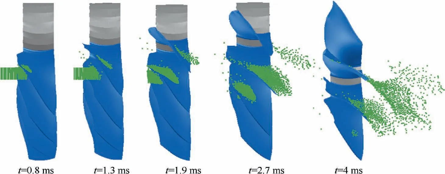
Fig. 24 Sequence of bird impact on a rotating full fan assembly at various times.
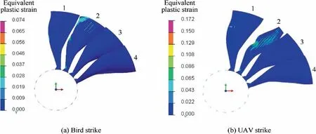
Fig. 25 Equivalent strain in fan blades impacted by bird or UAV.
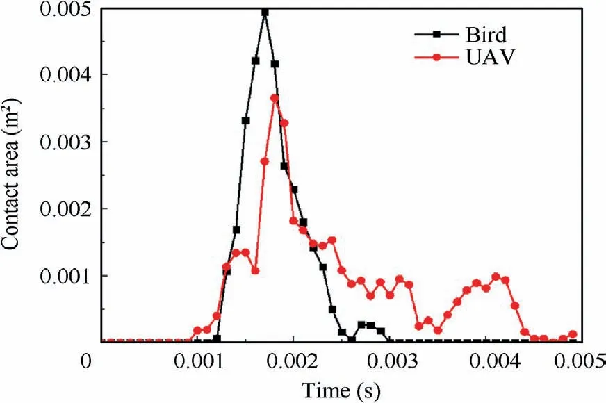
Fig. 27 Contact areas of UAV vs bird striking on blade 2.
5. Conclusions
The impact of a UAV with engine blades is a highly nonlinear dynamics problem, which involves many fields such as aviation, mechanics, material and so on. At present, the research on the anti-FOD (foreign object damage) of engine blades mainly focuses on bird impact, hail impact and other issues,and have achieved more mature research results, and provides a more mature technical means for the relevant airworthiness verification. There are few researches on the anti-collision of engine blades against UAV, which is still in the initial stage.A numerical simulation of UAV impacting engine fan blade were studied in present paper. Some conclusions are obtained from the studies as follows:
(1) A 3D Geometric model and a corresponding finite element model of small UAV is established in present paper.The good agreement on plate damage and deformation between the numerical simulation and test results indicated that the numerical simulation method presented in this paper is reasonable.The numerical simulation model of UAV strike with rotary primary compressor in present paper can be used to evaluate the anti-UAV strike performance of the blades.
(2) The impact process between the UAV and a single blade can be divided into two typical stages: cutting and impact.Cutting mainly leads to the failure of the leading edge material, and impact mainly leads to the plastic deformation of the blade.
(3) For the same mass of bird and UAV,the damage caused by UAV striking fan blade is more serious,and 1.345 kg UAV striking fan blade of typical civil aviation engine is enough to cause damage to flight safety.
(4) The numerical simulation of bird strike fan blades with the same mass and speed as UAV was carried out.Compared with the results of damage caused by UAV,although the same mass of bird projectile and UAV all collided with four blades, the impact damage of UAV is more serious.
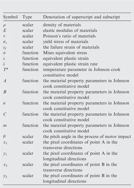
Fig. 27 shows a comparison on contact area of the UAV and the bird impacting with blade 2. It can be found that the contact area between the bird and the blade is larger. It can be explained that the impact damage of UAV with the same mass is more serious than that of bird projectile. For soft impact,the bird projectile spreads rapidly after contacting with the blade,increasing the contact area,so as to reduce the damage near the impact location. For the impact of hard objects,UAV is not as easy to disperse as bird projectile, so it is easy to cause instantaneous stress concentration at the moment of impact, so as to reach the strength limit of materials.
Declaration of Competing Interest
The authors declare that they have no known competing financial interests or personal relationships that could have appeared to influence the work reported in this paper.
Acknowledgements
This study was supported by the Civil Aviation Security Capacity Building Fund and the Civil Aircraft 13thFive Year Pre Research Project (No. MJ-2018-F-18).
 CHINESE JOURNAL OF AERONAUTICS2021年10期
- CHINESE JOURNAL OF AERONAUTICS的其它文章
- Direct dynamic-simulation approach to trajectory optimization
- A strong robustness open-circuit fault diagnosis strategy for novel fault-tolerant electric drive system based on d-q-axis current signal
- Nonlinear vibration response characteristics of a dual-rotor-bearing system with squeeze film damper
- Ground maneuver for front-wheel drive aircraft via deep reinforcement learning
- Recent advances in precision measurement &pointing control of spacecraft
- Transition characteristics for a small tail-sitter unmanned aerial vehicle
