A strong robustness open-circuit fault diagnosis strategy for novel fault-tolerant electric drive system based on d-q-axis current signal
Xuefeng JIANG, Shoshui WANG, Jie LI, Doyu WU, Wenxin HUANG,Zhenmo HAN
a School of Automation, Nanjing University of Science and Technology, Nanjing 210094, China
b College of Automation Engineering, Nanjing University of Aeronautics and Astronautics, Nanjing 210016, China
c Aviation Key Laboratory of Science and Technology on Aero Electromechanical System Integration, Nanjing 211106, China
KEYWORDS Dual-winding motor;Electric drive system;Fault-tolerant system;Open-circuit fault diagnosis;Permanent magnet motor;Strong robustness
Abstract To diagnose the Open-Circuit(OC)fault in the novel fault-tolerant electric drive system,based on d-q-axis current signal, a strong robustness diagnosis strategy is proposed and investigated. Fewer independent power supplies and converters are required in the novel fault-tolerant electric drive system based on Dual-Winding Permanent Magnet Motor (DWPMM), and the system’s reliability, usage ratio and power density have been improved compared to the conventional fault-tolerant motor drive system. However, the novel fault-tolerant electric drive system has the OC fault diagnostic false alarms issue when load changes suddenly or under light-load condition.And it lacks the research on the diagnostic method when the system encounters intermittent OC fault in power switches. By theory derivation, simulation and experimental verification, it can be concluded that the proposed strong robustness OC fault diagnosis strategy based on d-q-axis current signal can overcome the OC fault diagnostic false alarms issue when load changes suddenly or under light-load condition.And it can detect and locate the OC fault of single-phase winding in real time, and diagnose the intermittent OC fault of power switches.
1. Introduction
With the great advancement of electric drive systems in manufacturing, aerospace, electromobile, weapon equipment, subway, and medical industry, the high reliable electric drive systems have attracted considerable attention.1–5To achieve high efficiency, high precision, and fault-tolerant capacity,the electric drive system which possesses advantages of simple structure and high reliability has become the development direction of most countries.
However, the electrical fault of drive system is an objective reality under complex working conditions.Therefore, in order to preclude harmful influence, the topology of electric drive system with fault-tolerant performance has been widely researched in the last decade.5–8Compared with switched reluctance motor and double-redundancy motor, the faulttolerant permanent magnet motor drive system has better output performance and fault-tolerant capacity.9–11For electric drive system fault-tolerant operation, reliable fault diagnosis technology is an important premise. Electric faults in the universal motor drive system basically involve power switches and windings, where both Open-Circuit (OC) and Short-Circuit(SC) faults may take place. In fact, if there are faults taking place in windings, the two kinds of fault, OC and SC, correspond to open-switch and short-switch faults in converters respectively.10–12With regard to SC faults,many mature treatment schemes which are based on the drop voltage of the power switch through the hardware circuit already achieved a certain level of maturity.Moreover,anti-short circuit protection devices (such as fuse, peak voltage absorber) are considered in the process of hardware circuit scheme design.However, the power switches are prone to critical OC fault owing to over current,broken drive lines or bad contact of circuits.13Unlike the SC,a single-phase fault of OC in multiphase motor drive system will not cause obvious abnormal operation status. If detection and trouble shooting are not in time after the OC fault takes place, more serious faults will be brought about. Meanwhile, the DC component will cause a series of problems in the windings,such as a decline in torque,excessive heat, and insulation failure, and sometimes even damage the whole system.14–16
In motor drive systems, the diagnostic methods for OC faults can be divided into two types,one of which is the voltage signal diagnostic method,while the other is current signal diagnostic method. As to the voltage diagnostic method, although strong robustness and rapid diagnostic speed can be obtained,problems of poor generality in use, structural complexity and higher cost are ineluctable because of extra voltage sensors.In order to avoid extra sensors, the technique strategy considering the difference in actual and expected values of the pole voltage with no extra sensors was proposed in Ref. 17. The actual line voltage can be used to evaluate the measured pole voltage, and the use of additional hardware can be avoided.A detection method considering the four different current patterns caused by an open-switch fault in the inverter is proposed in Ref.18,which just uses the phase current without requiring additional devices. Furthermore, a new real-time diagnostic algorithm based on the instant voltage error was proposed in Ref. 9, which requires signals already available merely. An online open-switch fault diagnosis and localization strategy based on sampling theory was presented in Ref. 19, but the diagnostic algorithm proposed in Refs. 9 and 19 have drawbacks such as higher complexity and longer detection time.A novel zero voltage vector sampling method,which can overcome dead zones problem by moving the current reconstruction in low modulation region, was proposed in Refs. 20 and 21. In Ref. 22, a novel real-time diagnostic algorithm based on the actual motor phase currents was presented, but it requires reference signals from the main control system.
Among all the methods to diagnose OC faults, the mostly used one is the current detection method,which does not need any extra sensors.This method also has merits that the parameters are independent, and the system uses specialized control strategies.23–30In Ref. 23, in order to avoid the influence of measurement error, amplitude threshold and phase sector are used in current residual vector fault diagnosis. The methods for simultaneous OC faults and current sensor faults based on an adaptive threshold and observer-based approach in motor drive system were proposed in Refs. 25 and 26, respectively.However,the observer approach requires the knowledge of the machine parameters accurately. In Ref. 31, only the available current sensors were used and no-additional extra hardware was required. Moreover, some frontier intelligent control work has been carried out for fault diagnosis in electric drive system,such as the model predictive control fault diagnosis strategy with current harmonic under all kinds of OC faults conditions.32
The existing OC fault diagnosis strategies can make accurate diagnosis for the OC fault to some extent, but they encounter the false alarms issue in the case of light-load or when load changes suddenly.In this paper,a strong robustness OC fault diagnosis strategy for novel fault-tolerant electric drive system based on d-q-axis current signal is proposed and investigated. Unlike the traditional fault-tolerant motor drive systems, the novel one based on Dual-Winding Permanent Magnet Motor (DWPMM) requires fewer independent power supplies and power switches, and the system’s reliability, usage ratio and power density have been improved. However, the novel fault-tolerant electric drive system has the OC fault diagnostic false alarms issue when load changes suddenly or under light-load condition. And the research on the power switch intermittent OC fault diagnosis is lacked.The proposed strategy is necessary to deal with these issues of novel faulttolerant drive system.
In this paper, a novel fault-tolerant electric drive system based on DWPMM is proposed,which requires fewer independent power supplies and power switches. Besides, a strong robustness OC fault diagnosis strategy based on d-q-axis current signal is proposed to overcome the issues of the power switch intermittent OC fault diagnosis for the novel faulttolerant electric drive system, and the false alarms issue of OC fault diagnosis strategies under the conditions of sudden change of load or light-load.
2. Fault-tolerant electric drive system configuration based on DWPMM
2.1. DWPMM configuration
Configuration of the devised DWPMM which has been proposed and investigated in Ref. 33 by our team is shown in Fig. 1. As can be seen in Fig. 1, O and O′are the centers of the internal arc and the external arc of rotor magnetic steel respectively, and the distance between O and O′is defined as centrifugal height h.Rnis the internal arc radius of rotor magnetic steel, while Rwis the radius of external arc. In addition,θmis the external arc radian of rotor magnetic steel.33
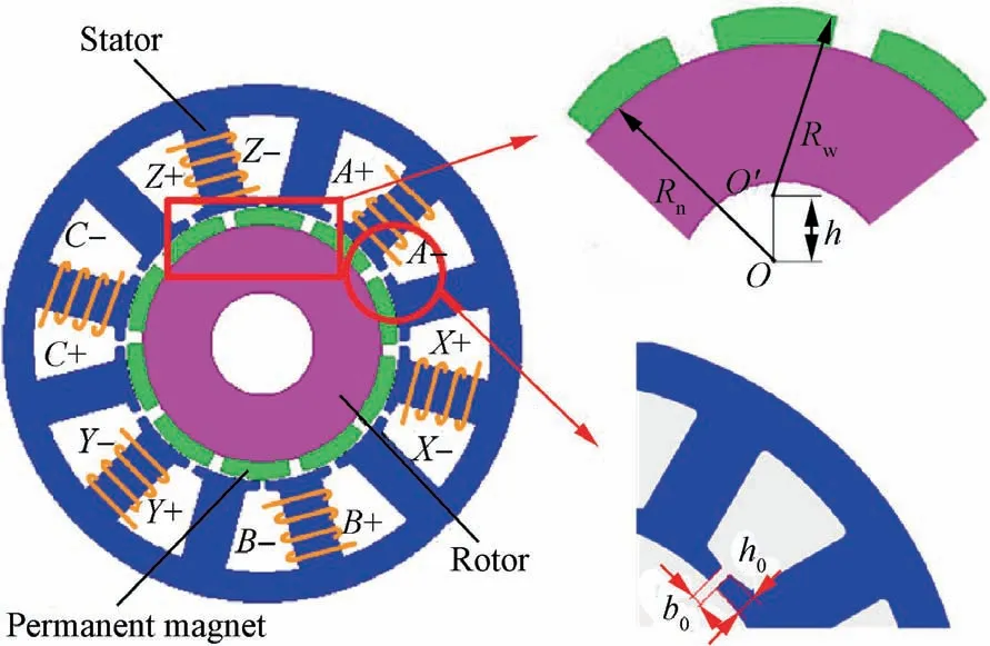
Fig. 1 Configuration of proposed DWPMM.
Meanwhile, it is a 12/10-pole motor with the stator composed of double independent three-phase concentrated armature windings (ABC and XYZ).33Because the successive coils are isolated by one tooth, the mutual inductance between neighboring phase windings is very small, so the motor possesses thermal isolation and magnetic isolation capability. To address the issue of the overlarge SC current, self-inductance is supposed to be big enough.In addition,by optimizing outer diameter centrifugal height of rotor permanent magnets,it was effective to raise the air–gap radial flux density sinusoidal performance and weaken components of high harmonic. Hence,the sinusoidal degree of no-load back Electromotive Force(EMF) can be optimized by this means, and it also cuts down the cogging torque ripple.
2.2.Topology configuration of conventional high reliable electric drive system
Professor B.C. Mecrow’s team first proposed a 6-phase/8-pole fault-tolerant permanent magnetic motor, and professor D.Howe’s team presented a fault-tolerant permanent magnet brushless motor with a modular structure.2On this basis, as shown in Fig.2,a 6-phase modular fault-tolerant motor is proposed, every phase of which is driven by a corresponding Hbridge with a DC power supply. Besides, concentrated armature windings are used for the alternate teeth. Hence, the motor drive system has properties of physical, electrical, magnetic, and thermal isolation. Considering the purpose of cost down and mass manufacturing, the modular construction is also beneficial. Nevertheless, a negative consequence of relatively high failure rate has been brought, as the system contains 24 converters and 6 standalone power supplies.2,7,8
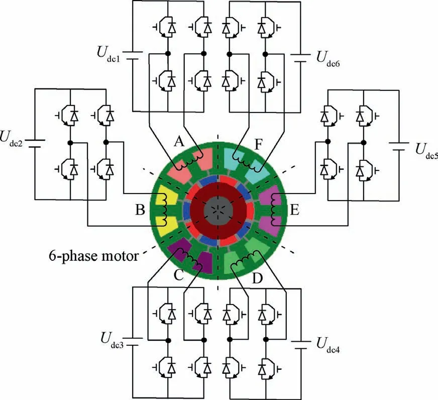
Fig. 2 H-bridge drive system of 6-phase fault-tolerant permanent magnet motor.
The triple Permanent Magnet Assisted Synchronous Reluctance Machine(PMA SynRM)drive system is shown in Fig.3.Combining the topology of synchronous reluctance rotor with embedded permanent magnets improves the capacity for faulttolerance. Isolation and non-overlap between the three sets of 3-phase windings are accomplished as the configuration of these windings is separate and segregated. A normal 3-phase converter enabling rapid assembling and cost reduction is adopted for each set of 3-phase windings. In the case of winding OC faults and power switch OC faults, the fault set winding power switches drive signal is turned off, and the overall power is provided by the remaining normal 3-phase inverter.The proposed winding isolation scheme is also suitable for the application of synchronous reluctance motor and induction motor in key situations.34
As shown in Fig.4,two drive systems of DWPMM are primarily composed of 1 high-reliability dual-winding permanent magnet motor,2 sets of three-phase full-bridge drive circuits,2 independent DC power supplies,and 2 sets of braking circuits(resistor R1,power switche S1and R2,S2).35Among them,the two sets of windings of DWPMM are controlled by independent three-phase full-bridge drives respectively. Compared with conventional modularized H-bridge drive topology,fewer independent power supplies and power switches are needed.Since the drive circuits and power supplies are separate,a good electrical isolation feature is acquired.
But this topology of drive system has low utilization, the rate of which is only 50% when it operates under the faulttolerant condition, as only the normal one set of windings is put into use Refs. 2 and 7. For example, if it has a failure in the Phase-C winding, the corresponding set of windings(namely Phase-A,-B and-C windings)will be removed.Sometimes, there is merely one power source system in the electric drive system, and thus, the drive system of DWPMM which has this kind of two identical parts is inadaptable to the system which merely provides one set of power supply.
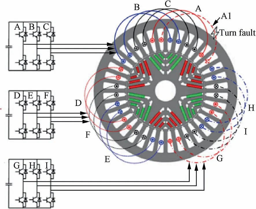
Fig.3 Triple permanent magnet assisted synchronous reluctance machine drive system.
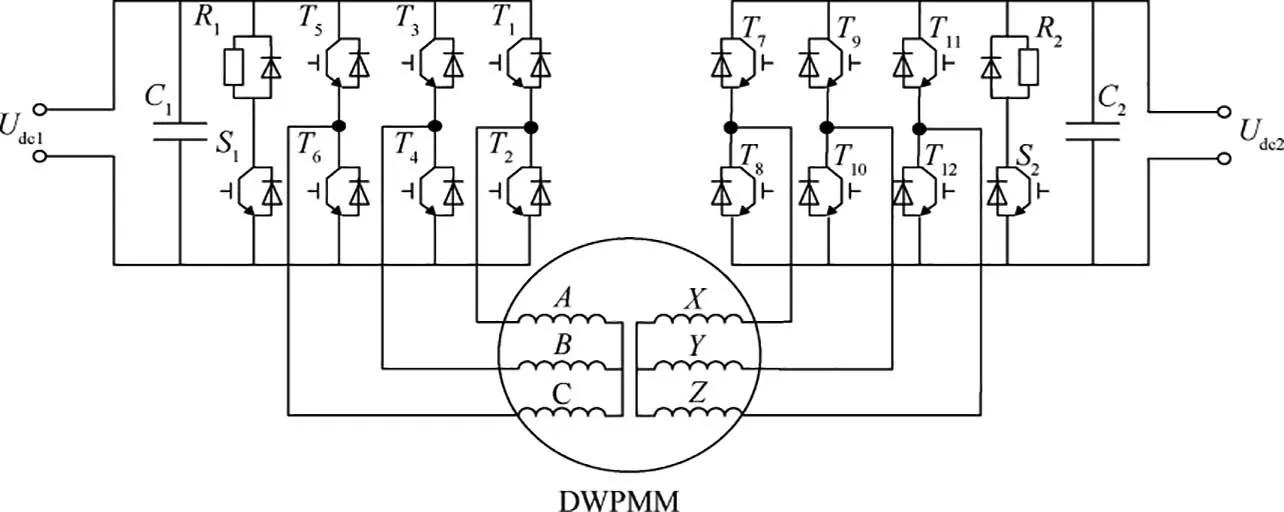
Fig. 4 Two three-phase drive systems of DWPMM.
Aimed at accommodating the system of a single power source, as shown in Fig. 5, our team put forward and researched the drive system in which the three-phase inverter has four bridge arms.35The configuration is comprised of two parts of inverters of this type and only one power supply.When a fault occurs(for instance,the winding fault in Phase-A or Phase-X) during operation of the system, the fourth leg (n1or n2) will substitute for the faulty ones respectively to maintain the normal performance of the system. However, the two redundant arms required in this system can also lead to excessive volume. Besides, when windings of two phases in one set have failure, the system is incapable of fault-tolerant operation.32
2.3. Proposed novel fault-tolerant electric drive system configuration based on DWPMM
As shown in Fig.6,in view of deficiencies of the former topology of fault-tolerant drive system, a new configuration of the electric drive system which has fault-tolerant capability on DWPMM basis is presented. The system consists of 1 DWPMM, 2 blocks of 3-phase full-bridge drive, 1 separate DC power supply, 6 fuse protectors (F1, F2, F3, F4, F5, F6),and 2 triacs (TR1and TR2). Fuses F1–F6are adopted to prevent a shoot-through fault caused by a simultaneous breakdown of power switches in the same phase. The 2 capacitors are used to modulate amplitude and phase of currents in the remaining normal phases after faults. This system requires only 1 power supply and fewer power switches, so that it has higher utilization ratio and reliability, as well as high power density. It can cope with various types of electrical faults,and the control strategies are simple to implement.
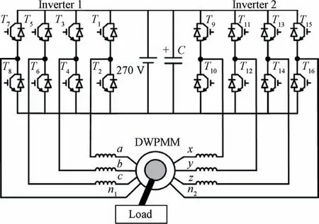
Fig. 5 DWPMM drive topology with three-phase four-leg inverter.
The half-bridge power conversion circuit with a neutral point has been constructed by utilizing TR1or TR2to improve the system fault-tolerant control performance. Table 1 reveals the summary of typical kinds of fault and corresponding actions. For instance, if there is a fault of OC in a winding(such as Phase-A winding), to compensate it, the driving signals of T1and T2are supposed to be interrupted and the triac(TR1) should be turned on, so that the system will be added a controllable degree of freedom due to half-bridge power conversion circuit with a neutral point which is constructed by utilizing TR1. By adopting the corresponding fault-tolerant control strategy, the system can still maintain stable and reliable operation after SC or OC fault occurs. When two power switches in the same bridge arm between the bus bars are broken down simultaneously,as the system uses single power supply,the supply power will be affected seriously.Thus,the fusescan be utilized to avoid serious impact caused by the shootthrough fault on the bridge arms. Hence, the system faulttolerant control performance can be improved greatly.
Comparison between the existing and novel electric drive systems which have fault-tolerant capacity shows that the novel electric drive system based on DWPMM has higher utilization ratio after faults occur. In addition, it is suitable for the single power supply drive system. Moreover, by applying the novel electric drive system, the fault-tolerant action can be carried out when the multi-phase winding OC or SC fault,bridge arm shoot-through, and multiple power switches fault occur synchronously, and the torque can be output normally under fault conditions.
3. Strong robustness OC fault diagnosis strategy based on d-qaxis current signal
3.1. Principle of OC fault diagnosis
Considering the situation of sudden load changes and operation under no-load or light-load condition, the strong robustness diagnostic strategy for the OC fault is proposed, and its principle is shown in Fig. 7. Concrete details of this principle are as follows: Clark/Park conversion, Low Pass Filter(LPF),Park’s vector processor,normalization processor,average value processor, range method, absolute value calculator,and average absolute value processor. Then the faults can be diagnosed and located in real time based on the fault diagnostic signals Mn, Dnand Qn. These points will be elaborated in the following section.
Taking ABC three-phase windings as an example, the realization process of OC fault diagnosis is analyzed. The XYZ three-phase windings have the same principle, so it is not repeated.
The measured phase currents of the motor are normalized using the modulus of Park’s vector, defined as
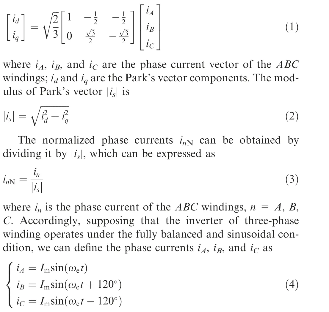
where Imis the maximum amplitude of phase current;ωeis the rotor electric angular velocity; t is time variable.
Meanwhile, the Park’s vector modulus |is| of three-phase currents can be expressed as

Hence,the normalized phase currents under normal operating condition are calculated by dividing the phase currents by the modulus of Park’s vector, which can be expressed as

Fig. 7 Principle of proposed OC fault diagnosis strategy.
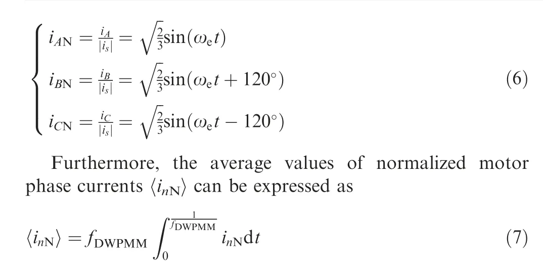
where fDWPMMis the phase current frequency, the normalized phase currents’ average value 〈inN〉 has three ideal state values under the conditions of normal or fault operation. During windings OC fault or under normal condition, the value of〈inN〉is equal to 0.When the system operates under lower Insulated Gate Bipolar Transistor (IGBT) (T2, T4, T6) OC fault condition, the value of 〈inN〉 is equal to 0.2599 and it is equal to -0.2599 under the upper IGBT OC fault condition.
Due to the current sampling error, the calculated value of〈inN〉 is not equal to 0 accurately in the normal state or under the winding OC fault condition.Hence,the normalized current average diagnostic variables Inare introduced,and they can be expressed as

where I0is the normalized average current diagnostic constant.In order to satisfy various load conditions and prevent false alarms,I0is set as 0.1,which is 0.5%of the rated current value.According to the normalized current average diagnostic variables In, the normalized average current fault diagnosis criterion can be given as

where Mnis the fault diagnosis signal,the value of Mnis equal to HMunder the lower IGBT OC fault condition,equal to NMunder normal or winding OC fault condition,and equal to LMunder the upper IGBT OC fault condition.
Based on the normalized phase current inNobtained in Eq.(7),the normalized motor phase current average absolute value〈|inN|〉 can be expressed as

When the motor electric drive system operates under the normal condition, the average absolute values of the normalized motor phase currents under the normal condition γ can be expressed as
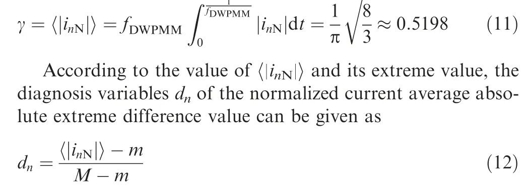
where M is the maximum value of〈|inN|〉,M=γ;m is the minimum value of 〈|inN|〉, m = 0.
Hence, by judgment criterion of the extreme value difference of average absolute current value,the normalized average current fault diagnosis criterion can be given as

where Dnis the fault diagnosis signal of extreme difference with the normalized average absolute current. Under normal conditions, Dnis equal to ND. Under conditions of OC fault in IGBTs, Dnis equal to HD. Under conditions of OC fault in windings, Dnis equal to LD.
In view of the intermittent fault of the power switch which exists in the drive system due to ageing circuits and poor electrical connection, only adopting the rules stated in Eqs. (12)and (13) may cause the intermittent fault being diagnosed as normal operation. The average current value fault judgment criterion of the normalized phase current absolute value is consistent with Eq.(13),and a new normalized phase current average diagnosis variable judgment criterion is introduced to realize the system fault alarm and guarantee the system’s security and reliability.

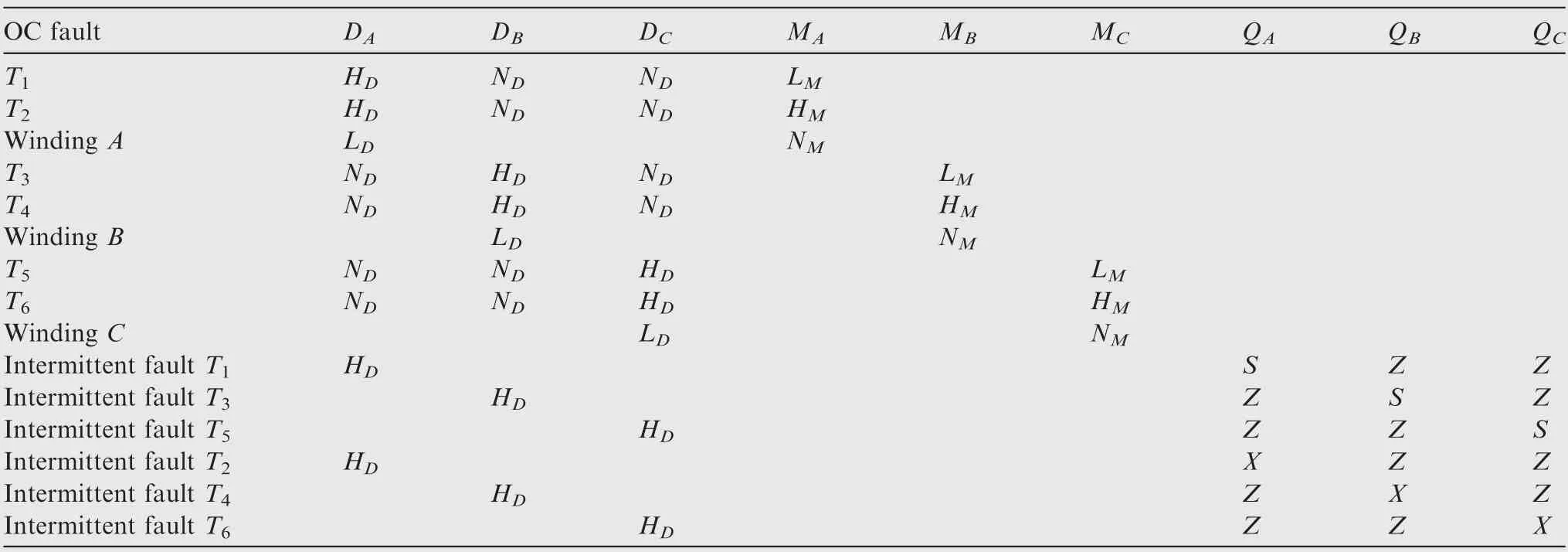
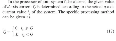
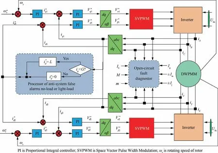
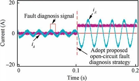
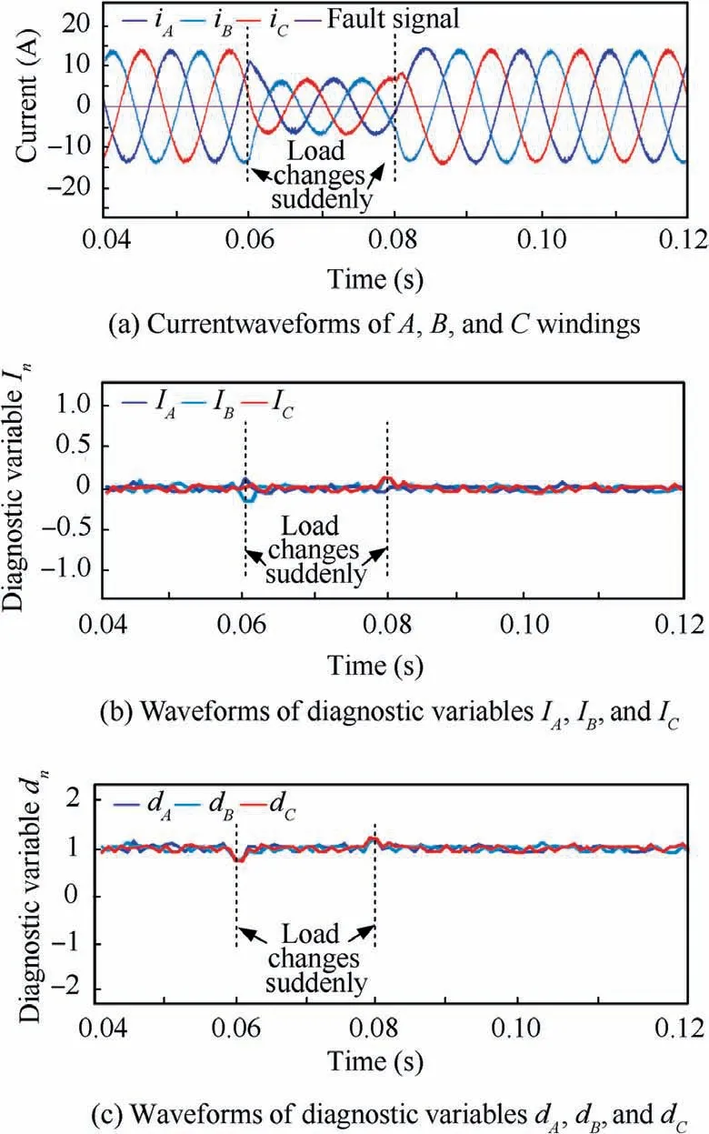
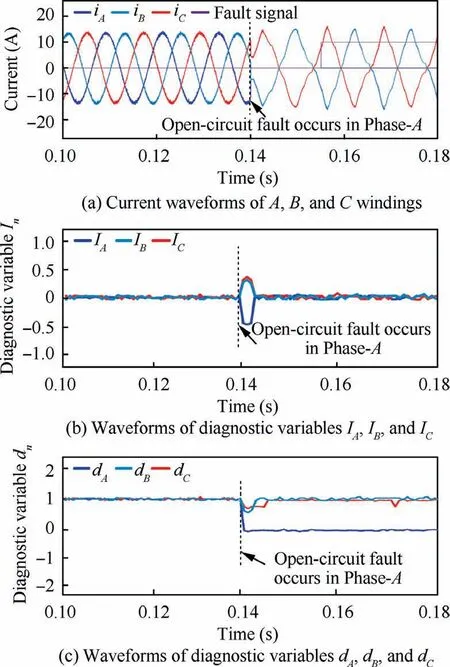
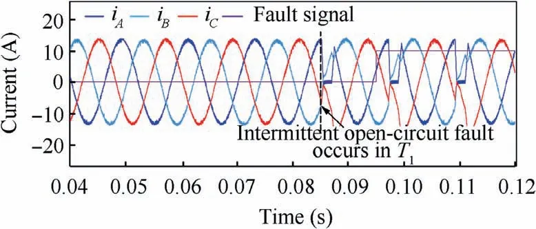
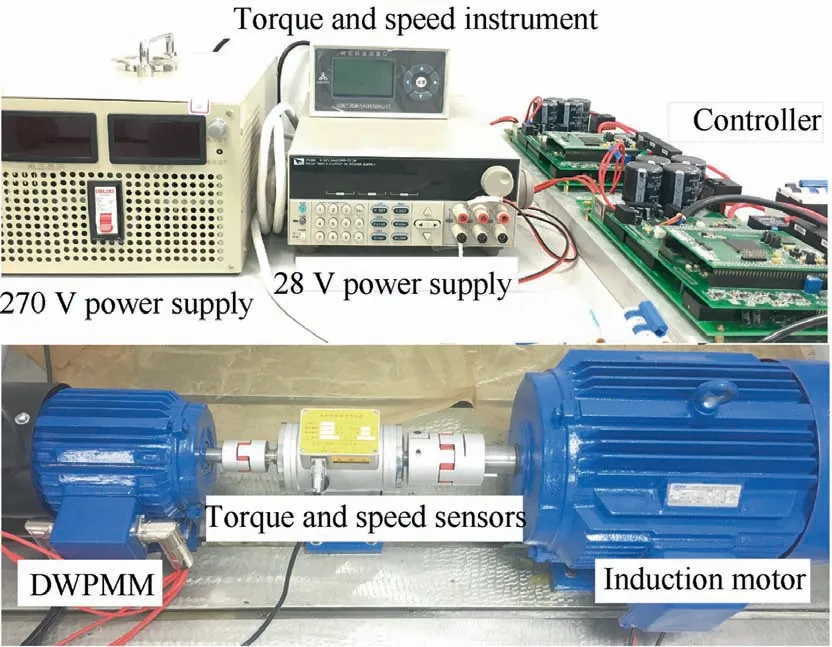
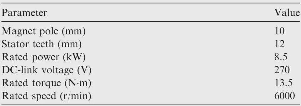
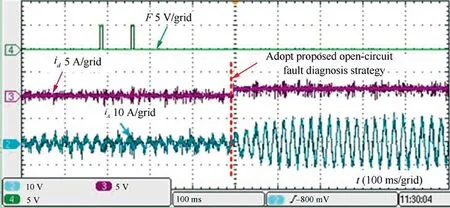
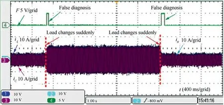
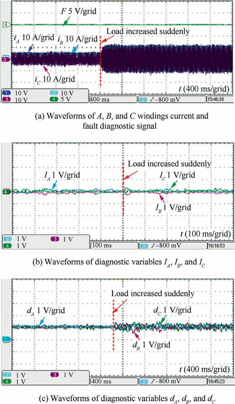
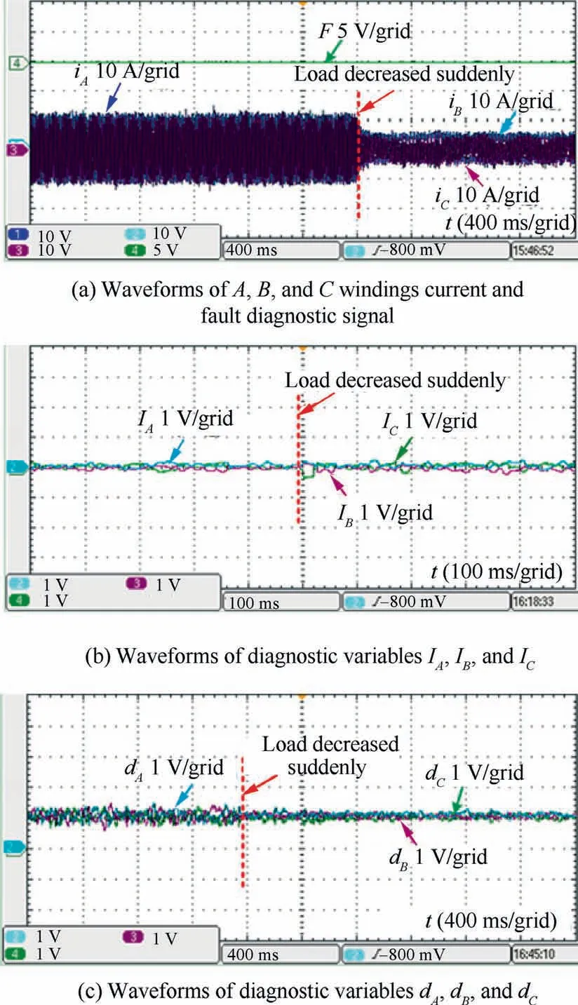
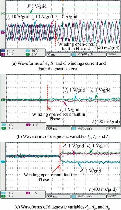
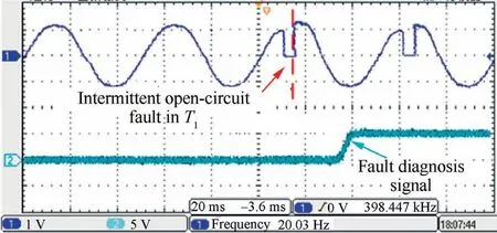
where Ignis the diagnostic variable of power switch intermittent OC fault; Igis the average current diagnostic constant of OC fault in the power switch,Ig=0.01;Ipand Ijare power switch intermittent fault diagnosis; Itis the average current diagnostic threshold of OC fault in the power switch; Qnis the power switch intermittent fault diagnosis signal. The diagnostic variables Igntally with Ij According to the normalized average current extreme difference fault diagnosis criterion and the normalized average absolute value extreme difference fault diagnosis criterion,the OC fault diagnosis and location as shown in Table 2 can be obtained.Fault types and specific fault position can be identified accurately under different conditions by combining Mn,Dnand Qn, when the OC happens, as shown in Table 2. As shown in Fig.8,a strong robustness diagnostic strategy for OC faults in the novel electric drive system is proposed based on d-q-axis current signal. This strategy is comprised of a robust diagnostor for OC faults, as well as a processor of anti-system false alarms when system service operates under no-load or light-load conditions suddenly. Table 2 Diagnostic signatures for OC faults. As for this strongly robust fault diagnosis strategy for OC faults on the d-q-axis current signal basis, concrete details are as follows:where G is the judgment threshold and its value is 20% of the rated current. When iqis less than G, it means the system in light-load or no-load operation, and meanwhile, the current injection value of d-axis is L. Substituting the sampling values of phase current and the constants into the OC fault diagnosis device, the normalized average current fault diagnosis signal Mn,the normalized average absolute current extreme difference value fault diagnosis signal Dnand the power switch intermittent fault diagnosis signal Qncan be obtained.Fault types and precise positions of the OC fault under different conditions can be confirmed according to Table 2. Fig. 8 Proposed strong robustness OC fault diagnosis strategy based on d-q-axis current signal. Fig. 9 Simulation comparison between traditional strategy and proposed strategy under light-load condition. Fig.9 shows the simulation result of the conventional OC fault diagnosis strategy and the proposed strong robustness strategy under light-load condition. Under light-load conditions,adopting the conventional strategy will result in the issue of false alarms. After the strong robustness fault diagnosis strategy proposed in Section 3.2 is adopted,the fault diagnosis signal keeps at a low level all the time, and the issue of false alarms does not occur. Accordingly,it is verified that the false alarm issue can be eliminated by applying the proposed strategy, and the fault diagnosis signal keeps at a low level unceasingly. Fig. 10 Simulation results of proposed OC fault diagnosis strategy when load changes suddenly. Adopting the proposed fault diagnosis strategy, Fig. 10(a)–(c)illustrates the results of simulation under the conditions of sudden load change. Waveforms of three-phase current in A, B,and C windings are presented in Fig. 10(a). The waveforms of normalized average current diagnostic variables IA, IB,and ICare shown in Fig. 10(b). The waveforms of diagnostic variables dA, dB, and dCare shown in Fig. 10(c). At 0.06 s, the load was reduced sharp from 10 N∙m to 5 N∙m. Then, the load was increased from 5 N∙m to 10 N∙m at 0.08 s. From Fig. 10, values of the diagnostic variables Intogether with values of the diagnostic variables dncome into some undulations as there is a sudden change of the load,yet they are still within a normal range and stable. The diagnostic variables MA= NMand DA= ND. As shown in Fig. 11(a)–(c), the simulation of fault diagnosis has been made when an OC occurs in Phase-A, which is a single-phase fault. At 0.14 s, the OC fault occurring in Phase-A winding is simulated, which is a single-phase fault,and this is equal to removing the signals from gates of IGBTs T1and T2. Fig. 11(a) shows the waveforms of current in the windings,which are iA,iB,and iC,respectively.The waveforms of normalized average current diagnostic variables IA, IB, and ICare shown in Fig. 11(b). The waveforms of diagnostic variables dA, dB, and dCare shown in Fig. 11(c). Fig. 11 Simulation results of single-phase winding OC in Phase-A. Fig. 12 Simulation results of single IGBT intermittent OC in Phase-A. According to Fig. 11, the value of the normalized average current diagnostic variable IAis between-1 and 1 when there exists the OC fault in Phase-A winding, and thus, MA= NM.The diagnostic variable dAwill decrease directly to 0, which is less than 1/3, and DA= LD. Take T1for instance to investigate the DWPMM drive system power switch intermittent OC fault,and the simulation results can be seen in Fig. 12. The power switch T1intermittent OC fault which is mostly caused by the loss of the drive signal can be diagnosed and located in real time. According to the proposed diagnosis signatures for OC faults signal and fault location which are shown in Table 2,consequently,it can be concluded from simulation results that the DWPMM-based high reliable electric drive system, with the presented strategy to detect OC faults, possesses the characteristic of strong robustness in the circumstances of sudden load change or the light-load. Meanwhile, the winding OC fault and the intermittent fault in power switches can be detected rapidly. As presented in Fig. 13, the experimental platform of the highly reliable electric drive system mentioned in Section 2.3 mainly includes DWPMM, controller, induction motor, frequency changer, torque and speed instrument, torque and speed sensors, and oscilloscope. The experimental platform is a towing system, where the DWPMM is the prime mover,the frequency converter controls the induction motor as load device, and the torque and speed sensors are applied to gauge the motor’s actual value of speed and torque. The essential parameters of the experimental DWPMM are listed in Table 3. Fig. 13 Test platform based on DWPMM. Table 3 Key parameters of tested DWPMM. Fig. 14 exhibits experiments of the conventional strategy for OC faults, and strongly robust diagnostic strategy for OC faults under light-load condition. According to Fig. 14, the issue of false alarms appears when we choose the conventional method to diagnose OC faults. However, the issue of false alarms can be eliminated after the devised strategy is adopted. The fault diagnosis signal F keeps at a low level and the diagnosis result is in a normal state. Fig. 14 Comparison between traditional strategy and proposed strategy under light-load condition. Fig. 15 False alarm results of conventional OC fault diagnosis strategy when load changes suddenly. The experimental results of the conventional OC fault diagnosis strategy based on the average current Park’s vector approach are shown in Fig.15.As revealed in Fig.15,if there is a sudden change of the load,the strategy will encounter false alarms. The reason is that the phase currents will be changed when the load increases suddenly, so that the calculated average current value in one period is not equal to 0. Meanwhile,the Park’s vector amplitude will also increase suddenly and be higher than the OC fault diagnosis threshold, and thus the results of fault diagnosis have false alarms. Fig. 16 Experimental results of proposed OC fault diagnosis strategy when load increased suddenly. Fig. 16(a)–(c) shows the experimental results of the proposed OC fault diagnosis strategy when the load increased suddenly.The waveforms of ABC windings and the fault diagnosis signal F are shown in Fig. 16(a), and the waveforms of diagnostic variables IA, IB, and ICare shown in Fig. 16(b). Fig. 16(c)shows the waveforms of the diagnosis variables dA,dB,and dC. Fig. 17 Experimental results of proposed OC fault diagnosis strategy when load decreased suddenly. Fig.18 Experimental results of single-phase winding OC fault in Phase-A. As presented in Fig. 16, values of diagnostic variables IA,IB,and ICare between-1 and 1,which is still in normal operation condition. The value of diagnostic variables dA, dB, and dCare more than 2/3,which is also in normal operation condition. The fault diagnosis signal F keeps at a low level all the time,and accordingly the issue of false alarms can be avoided. Fig. 17(a)–(c) reveals the experimental consequences of the OC fault diagnosis strategy when load decreased suddenly.The waveforms of ABC windings current are shown in Fig.17(a) when load decreased suddenly. And in Fig. 17(a), the fault diagnosis signal F can also be seen.The waveforms of diagnostic variables IA,IB,and ICare shown in Fig.17(b).Fig.17(c)shows the waveforms of the diagnosis variables dA,dB,and dC. From Fig. 17, it can be seen that the value of the normalized average current diagnostic variables IA, IB, and IChave some fluctuations, but it is still stabilized between -1 and 1 when load decreased suddenly. The value of diagnostic variables dA,dB,and dCare more than 2/3,which is still in the normal operation. The fault diagnosis signal F keeps at a low level,and accordingly the issue of false alarms can be avoided. Therefore,it can be concluded from Figs.16 and 17 that the proposed highly reliable electric drive system OC fault diagnosis strategy is of strong robustness. When the load changes suddenly, it is valid to deal with false alarms issues. Fig. 19 Waveforms of Phase-A winding current and fault diagnosis signal when single IGBT intermittent OC fault occurs in 3-phase inverter. Fig. 18(a)–(c) shows the experimental results of OC fault in Phase-A. The waveforms of ABC windings current and fault diagnosis signal are shown in Fig. 18(a). The waveforms of diagnostic variables IA, IB, and ICare shown in Fig. 18(b).The waveforms of diagnostic variables dA, dB, and dCare shown in Fig. 18(c). It can be seen from the results that, when the winding OC fault occurs in Phase-A, the value of Phase-A current will decrease to 0. The value of diagnostic variables IAis between-1 and 1, and thus, MA= NM. The value of diagnostic variable dAwill reduce to 0 immediately, and DA= LD. According to Table 2, after an OC in Phase-A occurs, the fault can be diagnosed immediately.The value of fault diagnosis signal F keeps at a low level before failure,while it will come to a high level after a period when OC fault occurs in Phase-A,and the fault can be detected and located accurately. Hence, it can be concluded that, by using the diagnostic strategy which is presented, with the DWPMM-based electric drive system which is highly reliable, we can effectively diagnose the OC fault in the single-phase winding, and thus good robustness can be achieved. Taking T1for instance to study the DWPMM drive system power switch intermittent OC fault, the experimental results are shown in Fig. 19. The power switch T1can be diagnosed and located in real time after an intermittent OC fault occurs due to the loss of the drive signal. Consequently, it is strongly robust for the devised diagnostic strategy to detect OC faults,and it can detect the intermittent fault of the power switch rapidly. (1) Compared to the conventional drive system of motors which has the fault-tolerant capacity,fewer independent power supplies and power switches are needed, and power density, reliability and utilization are enhanced when we choose the proposed novel DWPMM-based fault-tolerant drive system. (2) Advantages of the proposed novel DWPMM-based fault-tolerant electric drive system are reflected in several situations, as it can conduct fault-tolerant operation when multi-phase winding OC or SC faults, bridge arm SC fault,and multiple power switches faults occur at the same time, ensuring a normal torque output from the motor under fault conditions. (3) To overcome the issues of the power switch intermittent OC fault diagnosis for the novel fault-tolerant electric drive system,and the false alarms issue of OC fault diagnosis strategies under the conditions of sudden change of load or light-load,a strong robustness OC fault diagnosis strategy based on d-q-axis current signal has been proposed and investigated. The effectiveness of the proposed strong robustness OC fault diagnosis strategy based on d-q-axis current signal has been verified through theory analysis, simulation and experimental testing under different conditions. (4) It is effective to accomplish the location of OC faults in single-phase windings and its real-time detection, when using the presented strategy. We can make a conclusion that the proposed detection algorithm for OC,according to the simulating and experimental consequences, is strongly robust and highly reliable. Moreover, it has the potential to operate in aerospace and weapon equipment,or on other occasions that require high reliability. Declaration of Competing Interest The authors declare that they have no known competing financial interests or personal relationships that could have appeared to influence the work reported in this paper. Acknowledgements This work was supported by the National Natural Science Foundation of China (No. 51807094), China Postdoctoral Science Foundation (No. 2020M671499), Program for High-Level Entrepreneurial and Innovative Talents Introduction of Jiangsu Province, China (No. [2019]20), Aeronautical Science Foundation of China (No.20200028059001), and Jiangsu Planned Projects for Postdoctoral Research Funds,China (No. 2020Z145).3.2.Strong robustness diagnostic strategy for OC fault based on d-q-axis current signal
4. Simulation verification
4.1. Simulation comparison of diagnosis for OC fault between conventional fault diagnosis strategy and proposed strong robustness diagnosis strategy
4.2. Simulation results of proposed OC fault diagnosis strategy when load changes suddenly
4.3. Simulation results of single-phase winding OC fault
4.4. Simulation results of single IGBT intermittent OC fault
5. Experimental results
5.1. Experimental platform
5.2. Experimental comparison of OC fault diagnosis between conventional diagnosis strategy and proposed strong robustness diagnosis strategy
5.3. Experimental results of conventional OC fault diagnosis strategy
5.4. Experimental results of proposed OC fault diagnosis strategy when load changes suddenly
5.5. Experimental results of single-phase winding OC fault
5.6. Experimental results of single IGBT intermittent OC fault
6. Conclusions
 CHINESE JOURNAL OF AERONAUTICS2021年10期
- CHINESE JOURNAL OF AERONAUTICS的其它文章
- Direct dynamic-simulation approach to trajectory optimization
- Nonlinear vibration response characteristics of a dual-rotor-bearing system with squeeze film damper
- Ground maneuver for front-wheel drive aircraft via deep reinforcement learning
- Numerical simulation of a UAV impacting engine fan blades
- Recent advances in precision measurement &pointing control of spacecraft
- Transition characteristics for a small tail-sitter unmanned aerial vehicle
