Three-dimensional temperature prediction in cylindrical turning with large-chamfer insert based on a modified slip-line field approach
Cheng HU, Keji ZHUANG,b,*, Yunwei TANG, Jin WENG,Xioming ZHANG, Hn DING,
a Hubei Digital Manufacturing Key Laboratory, School of Mechanical and Electronic Engineering, Wuhan University of Technology, Wuhan 430070, China
b Institute of Advanced Materials and Manufacturing Technology, Wuhan University of Technology, Wuhan 430070, China
c AECC Guizhou Liyang Aviation Power CO. LTD, Guiyang 550000, China
d State Key Laboratory of Digital Manufacturing Equipment and Technology, Huazhong University of Science and Technology, Wuhan 430074, China
KEYWORDS Analytical model;Chamfered round insert;Dead metal zone;Prediction of temperature;Slip-line field
Abstract Chamfered inserts have found broader applications in metal cutting process especially in high-performance machining of hard-to-cut materials for their excellent edge resistance and cutting toughness. However, excessive heat generation and resulting high cutting temperature eventually cause severe tool wear and poor surface integrity,which simultaneously limits the optimal selection of machining parameters.In the present study,an analytical thermal–mechanical model is proposed for the prediction of the three-dimensional(3-D)temperature field in cylindrical turning with chamfered round insert based on a modified slip-line field approach. First, an innovative discretization method is introduced in a general 3-D coordinate system to provide a comprehensive demonstration of the irregular cutting geometry and heat generation zones.Then,a plasticity-theory-based slip-line field model is developed and employed to determine the intensities and geometries of every elementary heat sources in Primary Deformation Zones(PDZ),Secondary Deformation Zones(SDZ)and Dead Metal Zones (DMZ). At last, a 3-D analytical model is suggested to calculate the temperature increases caused by the entire heat sources and associated images.The maximum cutting temperature region predicted is found existing upon the chip-tool contact area rather than the tool edge.Moreover,the rationalities of cutting parameters employed are analyzed along with theoretical material removal rates and ensuing maximum cutting temperatures.The results indicate that the cutting conditions with large depth of cut and high cutting speed are more desirable than those with high feed rates.The proposed models are respectively verified through a series of 3-D Finite Element(FE)simulations and dry cutting experiments of Inconel 718 with chamfered round insert. Satisfactory agreement has been reached between the predictions and simulations as well as the measurements,which confirms the correctness and effectiveness of the presented analytical model.
1. Introduction
High cutting temperature is one of the critical factors that should account for the rapid wear of the cutting tool which would eventually shorten the tool life and cause poor surface integrity. It becomes more significant in the high-efficiency machining of hard-to-machine materials owing to the high hardness and high strength as well as the low thermal diffusivity. Hence, precise modeling of cutting temperature distribution is significant for the optimization of metal cutting process.In addition,the places where heat is mainly generated,i.e., the PDZ, SDZ and DMZ are existed with uneven located stresses and strains,which impede the development of the predictive models.1The incomplete understanding of the cutting mechanism and thermal–mechanical theory on the different deformation zones makes it challenging in the accurate modeling and prediction of cutting temperature.
In recent years, two main types of models, numerical and analytical models,have been published for temperature prediction by researchers. Numerical models are more prevalent in the prediction of temperature distribution with complex cutting geometries and time-varying cutting operations like milling and interrupted turning processes. However, this kind of models is more time-consuming compared with the analytical models.Current literatures utilizing numerical methods for temperature prediction cover both 2-D and 3-D cutting operations. Usui et al.2suggested a numerical methodology to calculate temperature distribution in 3-D cutting with singlepoint insert based on an energy consumption method. The computed cutting temperature on the rake face was then utilized in the construction of a characteristic equation between tool crater wear and cutting parameters.Lazoglu and Altintas3presented a thermodynamic model by means of finite difference method (FDM). Their model was able to predict both steady-state and transient temperature fields for continuous and interrupted cutting operations. Islam et al.4extended Lazoglu and Altintas’s FDM and developed a transient thermal model to predict 3-D temperature fields by numerically solving the partial differential equation of heat-mass transfer model. Ding et al.5predicted the steady-state temperature distribution in tool and workpiece material by developing a numerical 3-D prismatic thermal model for laser-assisted micro-milling (LAMM) process. List et al.6established a FE model to illustrate the temperature distribution in orthogonal cutting by means of numerical simulations. Frictional shear stress and heat partitioning factor were detailed analyzed between flowing chip and tool body interface considering the tool crater wear mechanism. Kara et al.7made an attempt to predict cutting temperature with the help of artificial neural network (ANN) algorithm. They confirmed that the learning capacity of the ANN was quite effective in predicting cutting temperature. Arrazola8suggested two FE models by utilizing Arbitrary Lagrangian-Eulerian (ALE) computing method.The influence from limiting shear stress and frictional condition at chip-tool interface on strain, cutting forces and cutting temperature distribution was investigated and considered in their models. Cakir et al.9brought forward a 2-D thermal model based on FDM. The sticking-sliding contact phenomenon between formed chip and tool rake face was incorporated in the numerical modeling. Unfortunately, the predicted isotherms by their model did not converge at the chip-tool junction area as a result of neglecting dynamic heat partition.
Analytical models are less intensive in computation compared with numerical models, but are limited in complicated cutting geometries and assumptions. Hence, analytical models are mostly developed for the determination of average cutting temperature or temperature field in orthogonal cutting process.Komanduri and Hou10developed a 2-D analytical model for determination of cutting temperature isotherms during orthogonal cutting. In their model, the top surfaces of chip and work-piece as well as the rake and flank faces were regarded as adiabatic boundaries to the semi-infinite media(i.e., tool, chip and workpiece), where imaginary heat sources with equal intensity were introduced to the original shear and frictional heat sources. Karpat and Ozel11extended Komanduri and Hou’s model with parallel-sided model in shear zone, and proposed an analytical methodology that can forecast cutting forces, stress and temperature distributions in orthogonal cutting. The thermal influence from tool flank wear land was considered as an additional friction power in their study. Huang and Liang12developed a similar analytical model with heat source images based on previous work by Carslaw and Jaeger13. Different from Komanduri and Hou’s model, the chip-tool interface was also treated as adiabatic boundary when introducing the images of both primary and secondary hear sources.Huang and Yang14found that the predicted thermal isotherms by Komanduri and Hou’s model were not consistent with actual observations.So they modified the model by introducing the heating time to the workpiece.Jiang et al.15presented an induced cutting temperature model to characterize the interrelationship between the varying heat flux and temperature distribution during interrupted cutting operations. The Salomon’s hypothesis, where the cutting temperature would increase firstly and then decrease with the accumulating cutting speeds, was validated by designing a group of interrupted cutting experiments in their study. Cui et al.16suggested an analytical model for the tool temperature prediction in end milling considering tool flank wear. They found that the heat partition at tool flank face increased with larger feed rate and lower cutting speed. Wu et al.17investigated the varying heat flux into tool body during end milling by dividing the heating in discontinuous milling process into growing and reducing phases. Two corresponding analytical models were developed considering real friction state and 1-D plate heat convection method for the two separate phases respectively. Recently, Liao et al.18conducted a research on the cutting temperature distribution and forces on bone milling operation. An innovated mechanistic model to demonstrate the temperature field in bone workpiece was developed by considering arc moving heat sources and varying heat flux. However, these released analytical solutions were mostly for 2-D temperature prediction with sharp insert out of the simplified chip-tool contact geometries in orthogonal cutting.To our best knowledge, a 3-D model for the prediction of temperature fields in oblique cutting utilizing analytical method has become a limited research focus in metal cutting.
Chamfered round insert has been widely applied into highperformance machining of hard-to-machine materials since it owns larger cutting area and superior edge resistance. However, the resulting high cutting temperature and rapid tool wear is the predominant cause for short tool life and low part quality.19This paper takes account the chamfered edge and provides an analytical model for precise temperature prediction for cylindrical turning process with chamfered round inserts, which could make considerable contributions to the optimal selection of cutting parameters and edge preparations for such insert in high-performance machining process. At first, an innovated 3-D discretization methodology is developed to address the complicated contact geometry and heat generation issues during cylindrical turning using chamfered inserts. Then, the distribution and intensities of the involved heat sources upon every discretized cutting element are determined with a modified slip-line field model. Detailed analysis of heat generation and partition in the DMZ is elaborated.Finally, a 3-D analytical model can be developed by integrating the entire temperature rise contributions from every single heat sources besides their images. Moreover, a pair of nonlinear heat partitioning models is applied to dynamically matching the temperature increases along the chip-tool interfaces. In addition, two kinds of verifications are employed to validate the thermal mode including 3-D FE simulations and cylindrical turning experiments with chamfered round inserts.The predicted 3-D thermal field results denote that the region with highest temperatures is at the chip-tool interface instead of the cutting edges, which is in satisfactory agreement with the experimental measurements and findings from the 3-D FE simulation.
This paper consists of five sections. A brief review of the previous researches on thermal modeling is presented in the first section.Then,in Section 2,a 3-D discretization approach is suggested for the irregular cutting geometry in 3-D cylindrical turning process with chamfered round insert.Section 3 presents a modified slip-line field approach to determine the intensities of each elementary heat sources.A 3-D thermal–mechanical model is established on the basis of the imaginary heat sources theory by integrating entire heat sources.The validations for the proposed models are carried out in the fourth section with a series of 3-D FE simulations as well as cylindrical turning experiments with chamfered round inserts. The contributions of the present research are concluded in the last section.
2. Geometrical modeling for round insert with large chamfer
2.1. Contact geometry between workpiece and tool
The introduction of chamfered edge equips the round cutting tool with superior edge resistance and prolonged service life.The contact geometry between the workpiece and tool becomes so complicated that it is rather challenging and limited to suggest a clear and comprehensive demonstration about the cutting mechanism with such kind of insert.
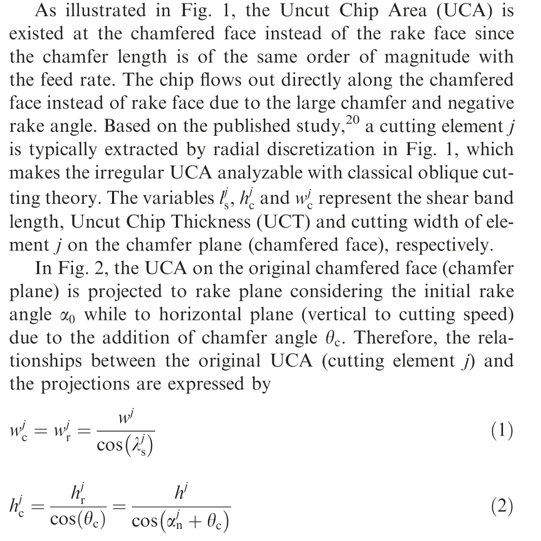
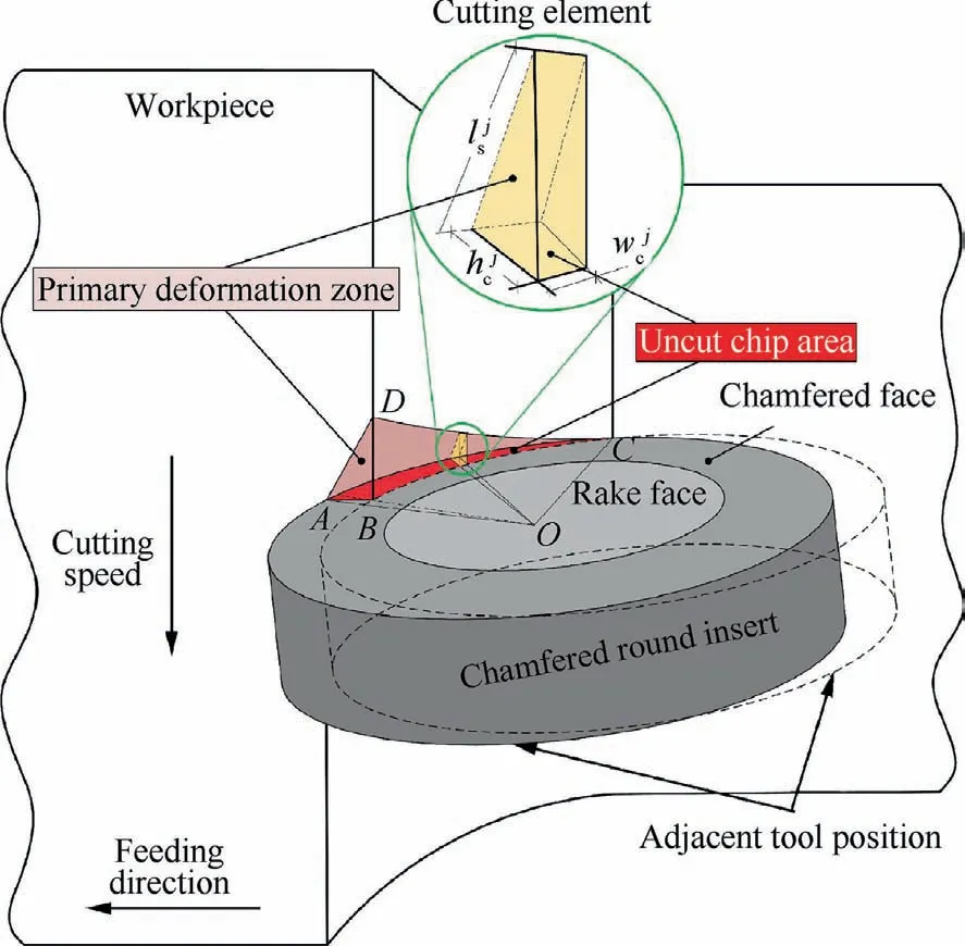
Fig. 1 Schematic view of cylindrical turning with chamfered tool.
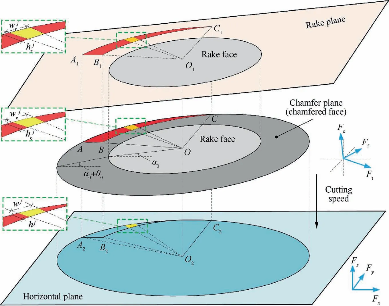
Fig. 2 Diagram of projections of UCA on assumed rake and horizontal planes.
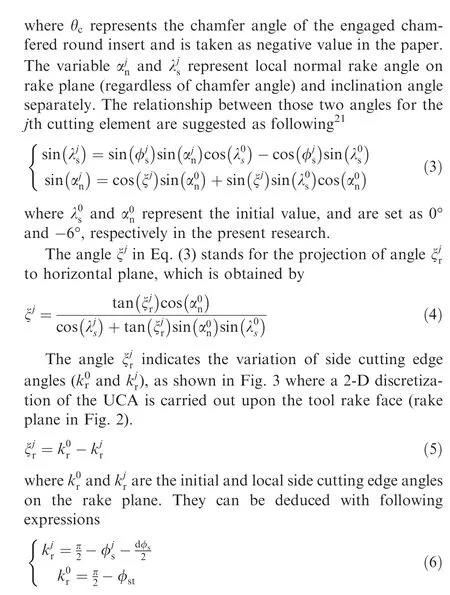
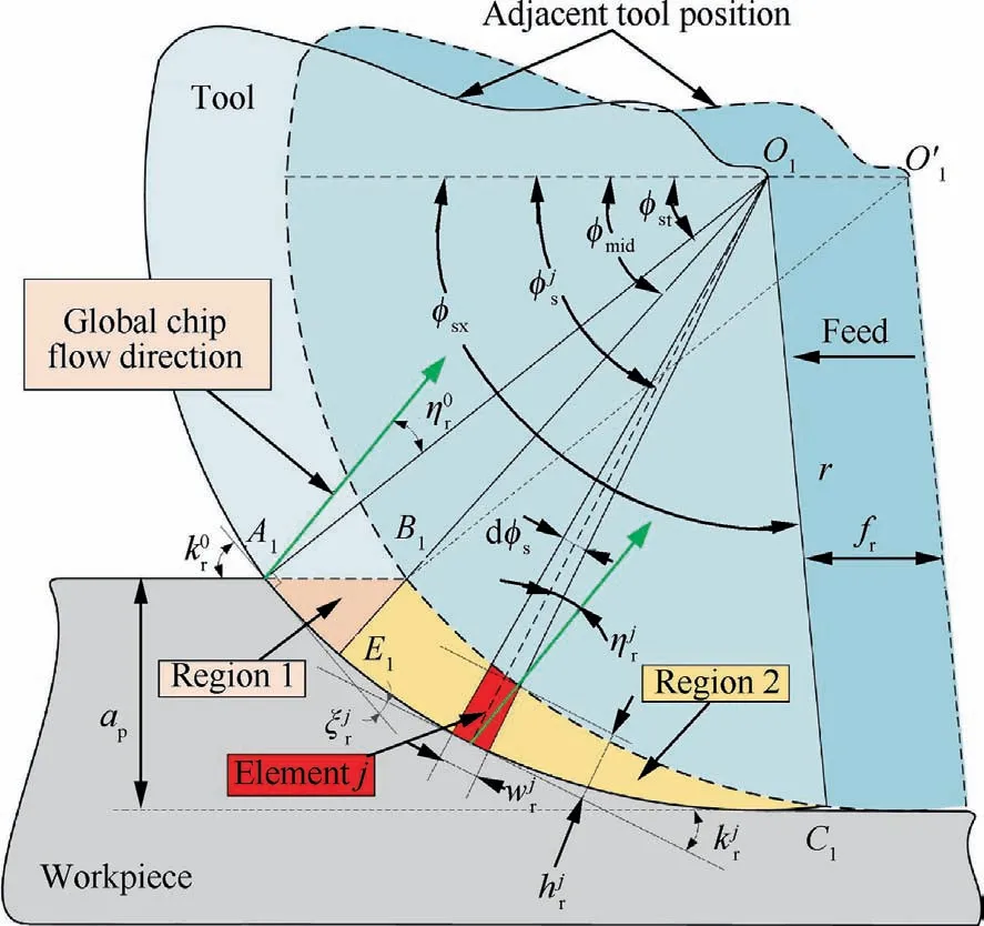
Fig. 3 Schematic view of discretization of UCA on rake plane.
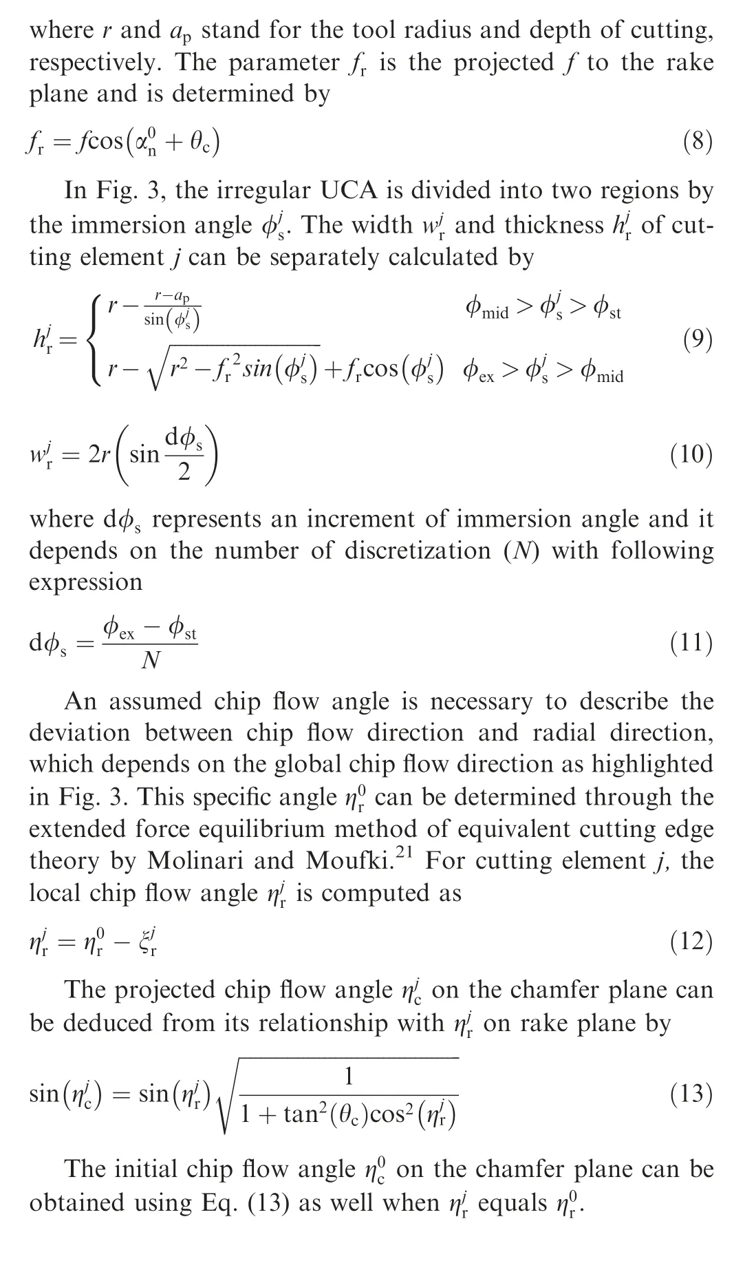
As illustrated in Fig. 3, the start angle φstat point A1, the middle angle φmidat point B1and exit angle φexat C1are dependent on the initial cutting parameters through following expressions

2.2. Contact geometry between chip and tool
Considering the variation of local chip flowing angle ηjc, the contact geometry between the formed chip and corresponding cutting element j should be analyzed individually. Hence,another discretization is carried out for the chip on the chamfer plane in Fig. 4.
As illustrated in Fig.4,two separate sections are introduced at cutting element j along chip flow and radial directions. The section along radial direction is in correlation with the radial discretization displayed in Fig.3.The pattern at chip flow section for each cutting element can be simplified as orthogonal cutting with negative rake angle. Therefore, a plasticitytheory-based slip-line field model from released study22is adopted to deal with the contact geometry between the local chip flow and the tool chamfered edge.

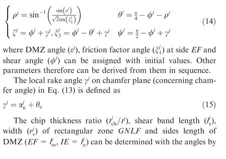
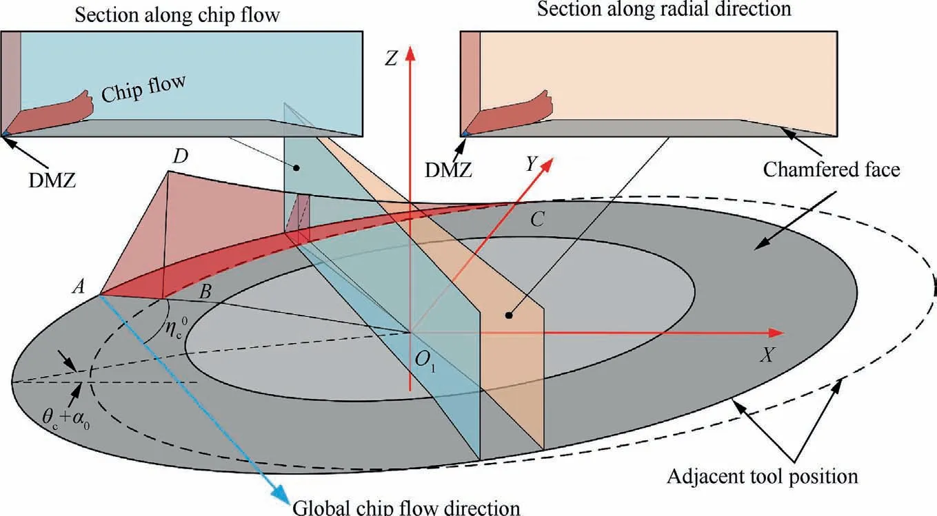
Fig. 4 Schematic view of discretized cutting element in 3-D coordinate system.
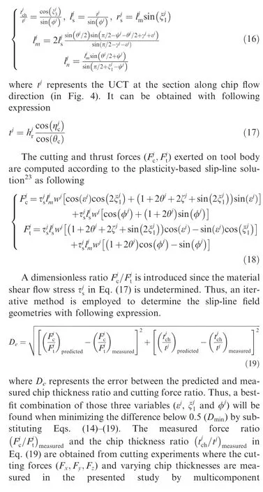
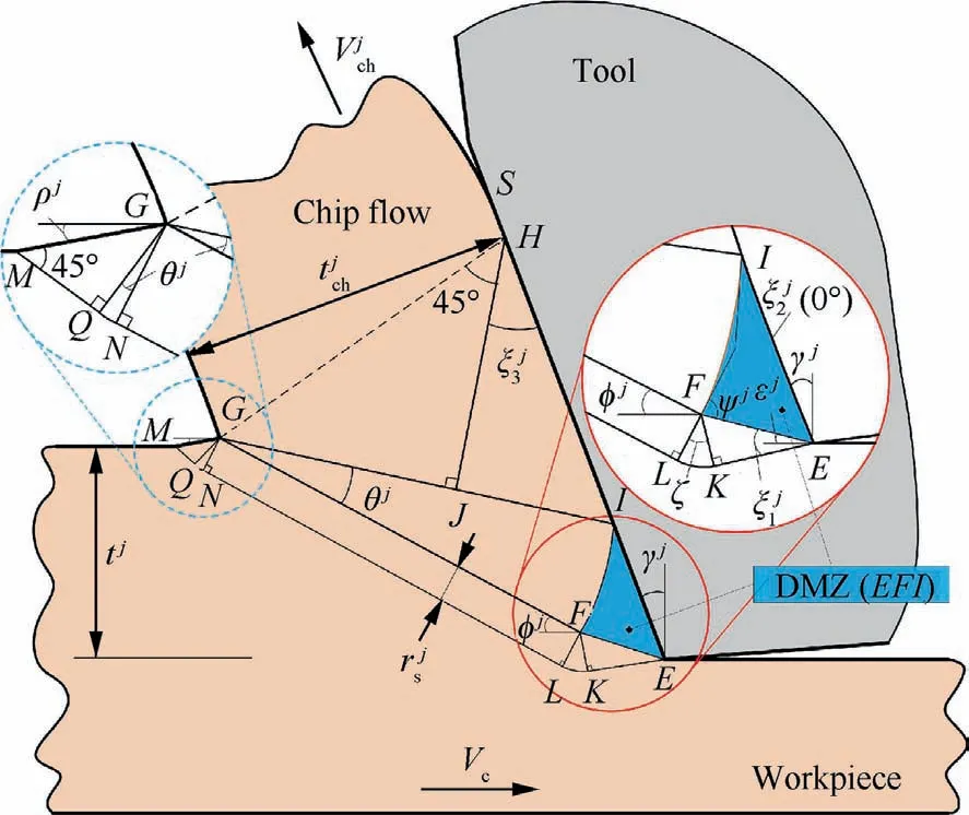
Fig. 5 Diagram of developed slip-line field model considering DMZ.
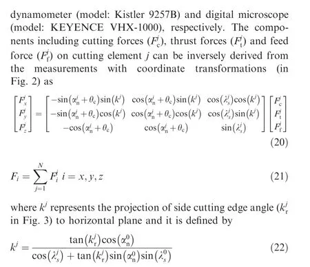
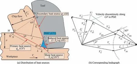
Fig. 6 Schematic view of the distribution of heat sources and corresponding hodograph.
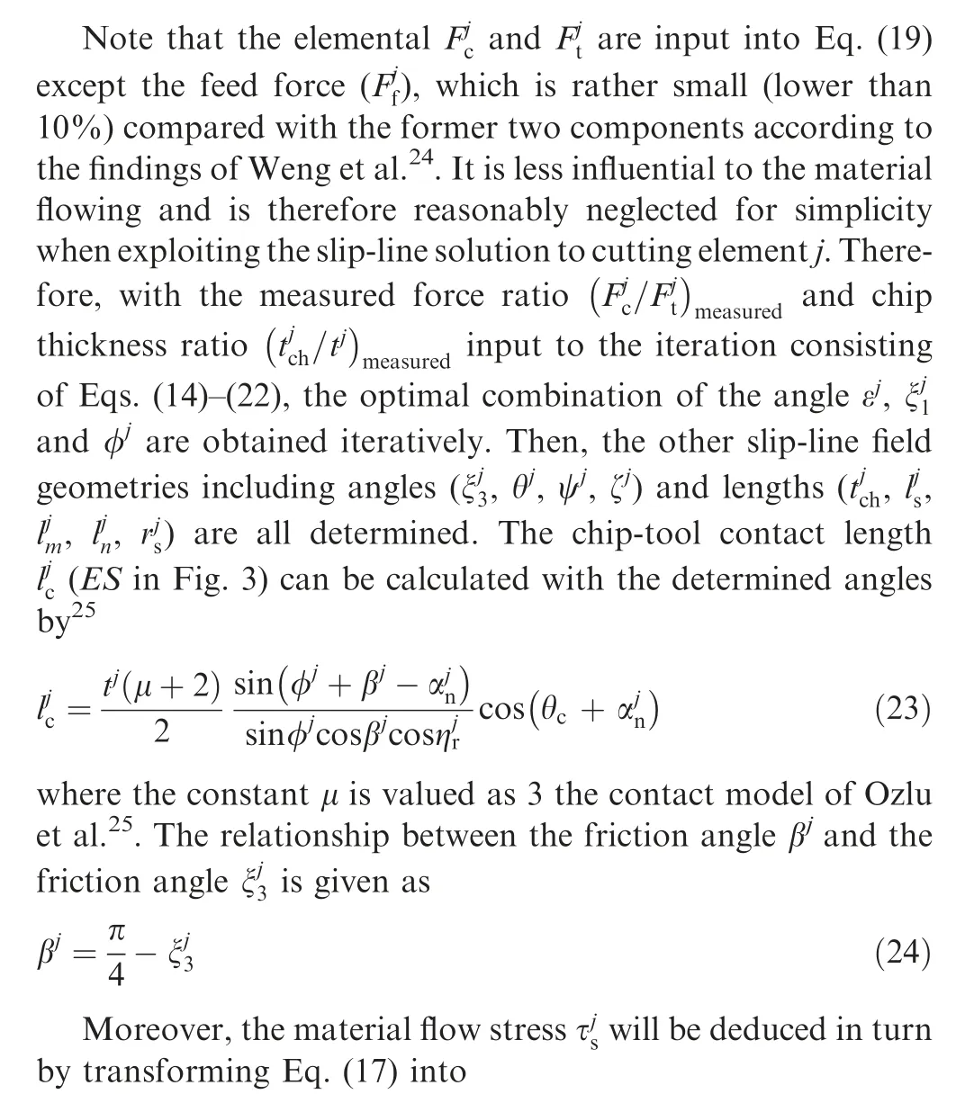
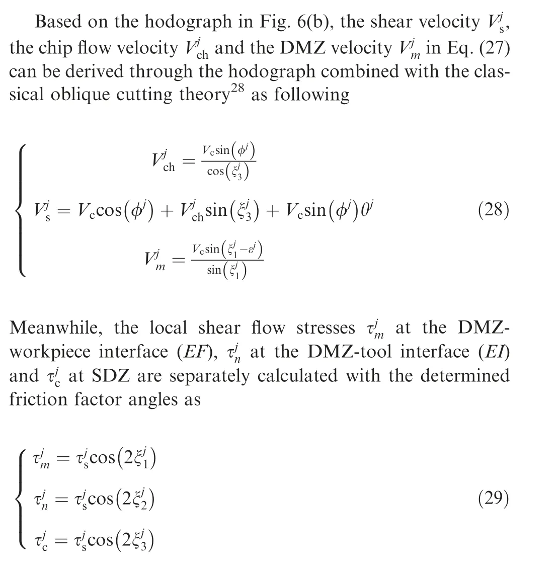

In the current study, the material flow stress is assumed unchanged with the cutting velocity, strain,strain rate or temperature since the workpiece material is regarded as perfectly rigid due to the plasticity theory.26
3. Thermal modeling for round insert with large chamfer
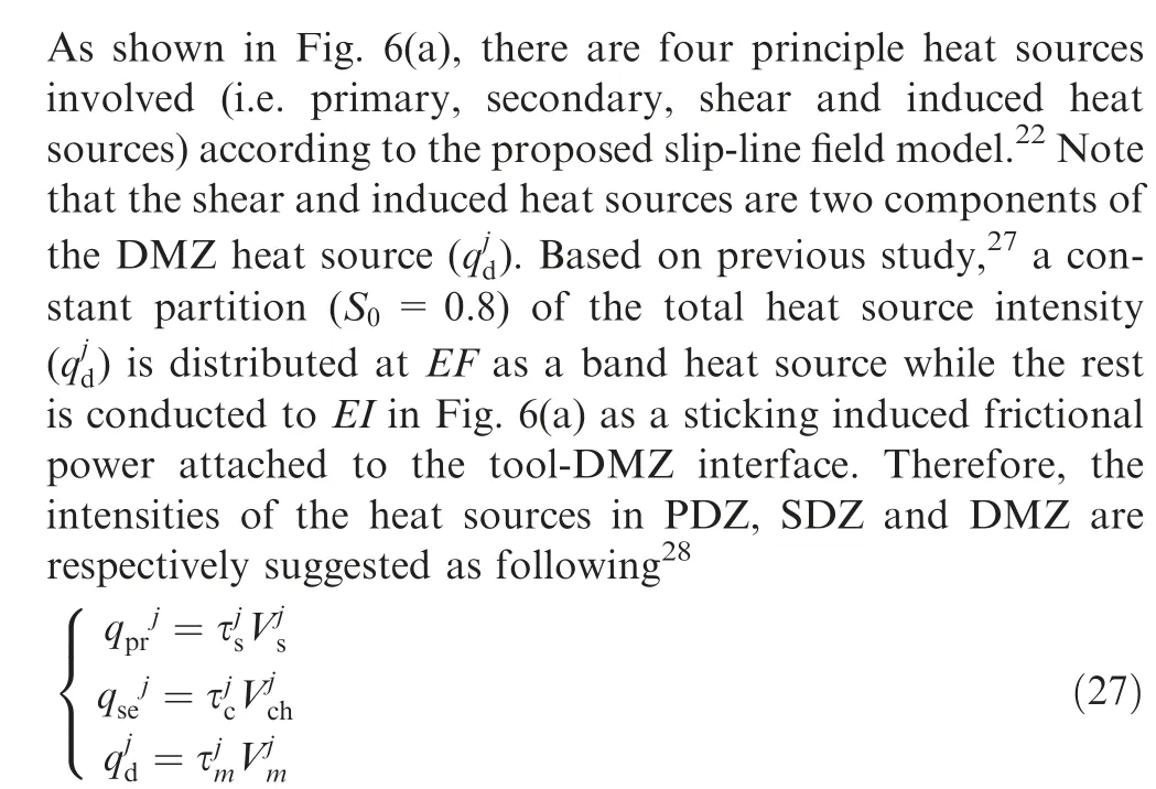
3.1. Determination of involved heat sources

3.2. Thermal modeling considering multi heat sources
With the determination of heat sources in PDZ, SDZ and DMZ, the resulting temperature rise in tool and chip can be determined by integrating the heating influences from each elementary heat sources. Based on the 2-D analytical models developed by Komanduri and Hou,10the chip,tool and workpiece can be regarded as semi-infinite media to model the temperature rise distribution in steady-state cutting condition. Hence, appropriate images are added symmetrically to the semi-infinite media (i.e. the chip, tool and workpiece) about the assumed adiabatic boundaries(i.e. upper surfaces of chip and workpiece and tool flank face). As shown in Figs. 7–9, the images of all the involved heat sources are introduced with specific boundaries, respectively.
Hence, the temperature rise inside chip is caused by a collective influence from the embroiled eight heat sources marked by ①–④in Fig.7 and ⑤–⑧in Fig.8,which can be calculated as
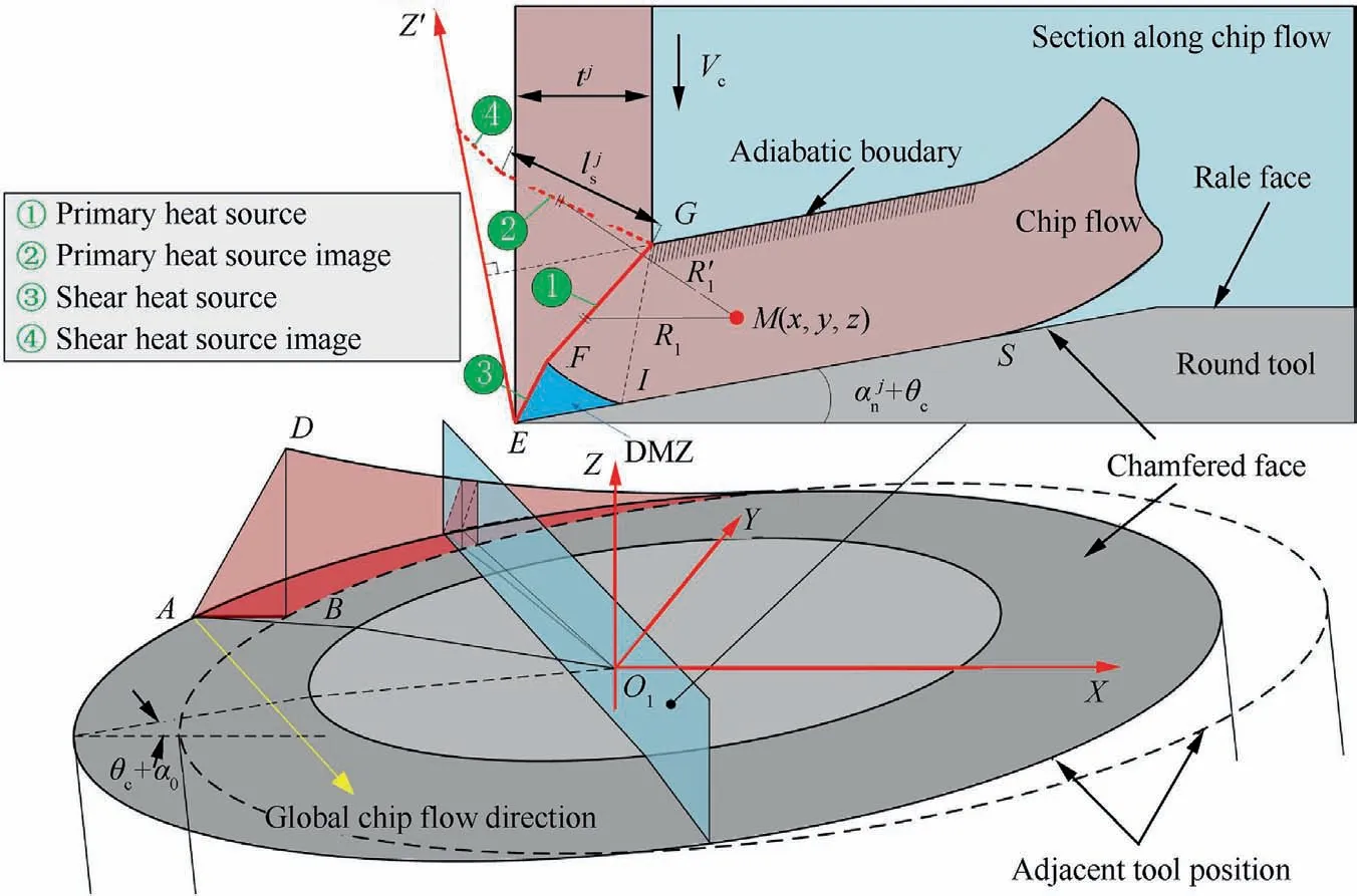
Fig. 7 Distribution primary and shear heat sources with related images considering chip upper surfaces as adiabatic boundaries.
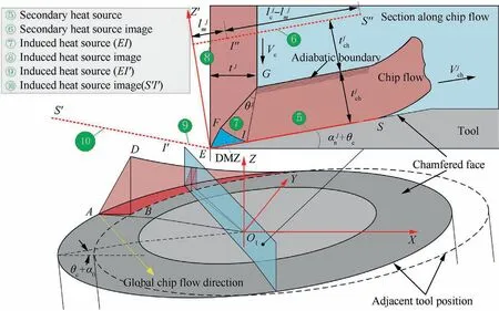
Fig. 8 Distribution the secondary and induced heat sources with related images considering the chip upper surfaces and machined surfaces as adiabatic boundaries.
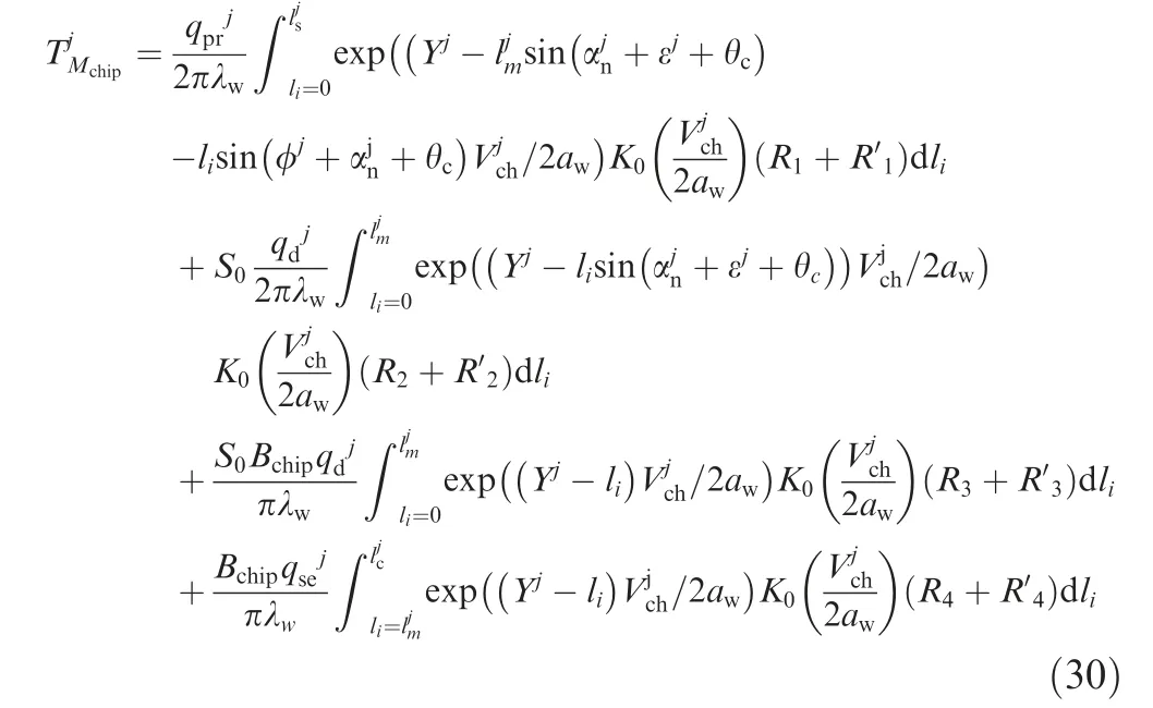
where the exponent Yjin the expression above is the modified coordinate in Y′axis for the point M(x,y,z)for that the original Cartesian system X-Y-Z has been transformed to X′- Y′- Z′with the point E as the center for modeling convenience. The coordinates of point M in new system can be obtained through the 3-D coordinate transformation matrix as
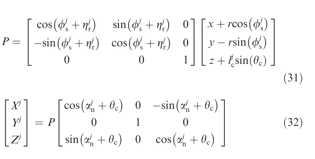
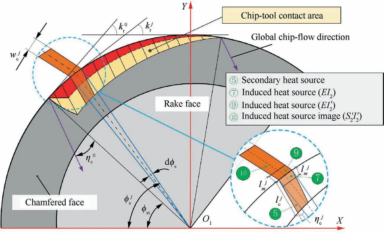
Fig. 9 Aerial view of the distribution of the secondary and induced heat sources along with their images with tool flank face being adiabatic boundaries.
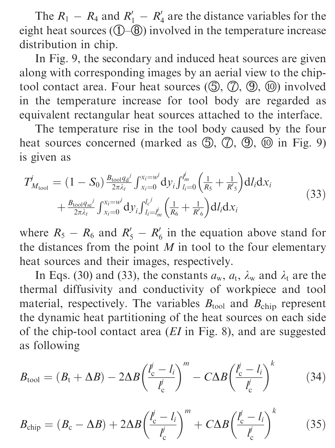
In the equations above,the variables Bc,Bt,ΔB,C,m and k are the adjusting coefficients for precise matching of temperature rise at the two sides along chip-tool contact length,which are supposed to be tuned with varying cutting parameters and tool edge preparations.The heating influence from heat source in the PDZ on the tool can be incorporated into the heat partition model based on the research of Huang and Liang.12The temperature at point M can finally be determined by integrating the heating influences from every associated heat sources by

where N represents the sum of total divided elements and Trthe room temperature with the value of 25°C. To give a comprehensive description of the developed 3-D thermal–mechanical model, a computational flow chart is suggested in Fig. 10 with inputs and outputs.
4. Verification of proposed thermal–mechanical model
4.1. Verification by 3-D FE simulation
The FE simulation method employed in the presented study is commercial package AdvantEdge(Version 7.1).It can provide a comprehensive and dynamic temperature distribution in chip, tool and workpiece, which is of great help in the investigation of cutting temperature distribution.30
Fig. 11 suggests an example of the imported chamfered round insert.There is a mesh refinement for the chamfered face(minimum tool element size: 0.01 mm) in order to capture the precise temperature distribution. There are thirteen 3-D FE jobs in total carried out with respect to the influence of cutting parameters and chamfer angle on temperature distribution for cylindrical turning with chamfered round insert.The design of the simulations is given in Table 1.
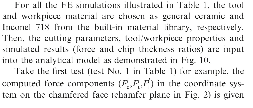
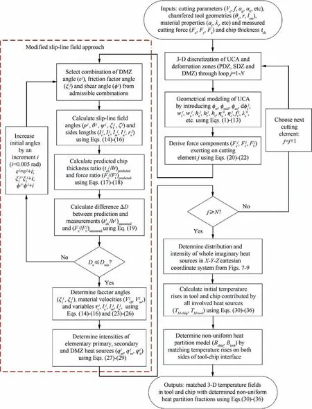
Fig. 10 Computational flow chart of 3-D thermal–mechanical model.
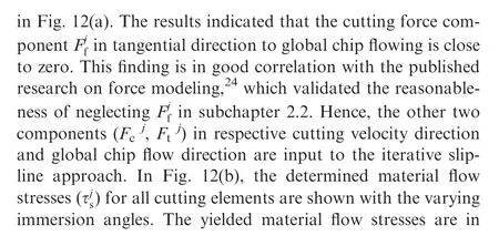
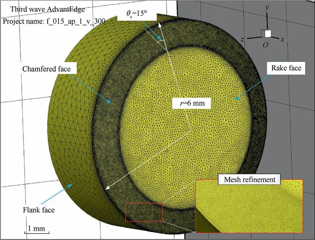
Fig. 11 Chamfered round insert with mesh refinement in AdvantEdgeTM.

Table 1 Design of 3-D FE simulations for cylindrical cutting of Inconel 718 with chamfered insert.

Fig.13 provides a typical variation of the determined intensities of the three predominant heat sources along the effective cutting edge(test No.1).It indicates that the all three intensity curves carry a similar three-stage distribution in the whole UCA,that is,a slow decrease in Region 1,then a nearly stable trend in most of Region 2 and a rapid surge at the end region.This phenomenon is accordance with variation of material shear flow stresses given in Fig. 12(b) and elementary UCA illustrated in Section 1. Besides, it is found that the intensities of both secondary and DMZ heat sources reveal an equivalent proportion to the intensities of the primary heat source. The calculated average proportion of the DMZ heat source intensities to primary ones is about 62%while that of the secondary heat source is 23%.
3-D and corresponding detailed view of the temperature fields on the chamfered round insert through the proposed model and FE simulation are compared in Fig.14. It is found that the region with top temperature values (Tmax) is not existed right upon the cutting edge but instead a certain distance(Ds)from it.This phenomenon is contrary to the findings of Weng et al.33since the nonlinear heat partition was not concerned in their analytical model. Moreover, the maximum interface temperatures are observed away from the tool tip in both FE simulations and practical machining processes,34which is in good correlation with the simulations and predictions in Fig. 14. The simulated highest interface temperature Tmaxis 1120°C in Fig. 14(b). The distance Dsfrom it to tool edge is measured as 0.138 mm. The predicted Tmaxis 1059°C and the distance measured to be 0.143 mm away from the edge. The errors for Tmaxand Dsin this typical simulation are 5% and 4%, respectively. Hence, the calculated highest cutting temperature besides its position by our 3-D thermal model coincides well with the 3-D FE simulation.
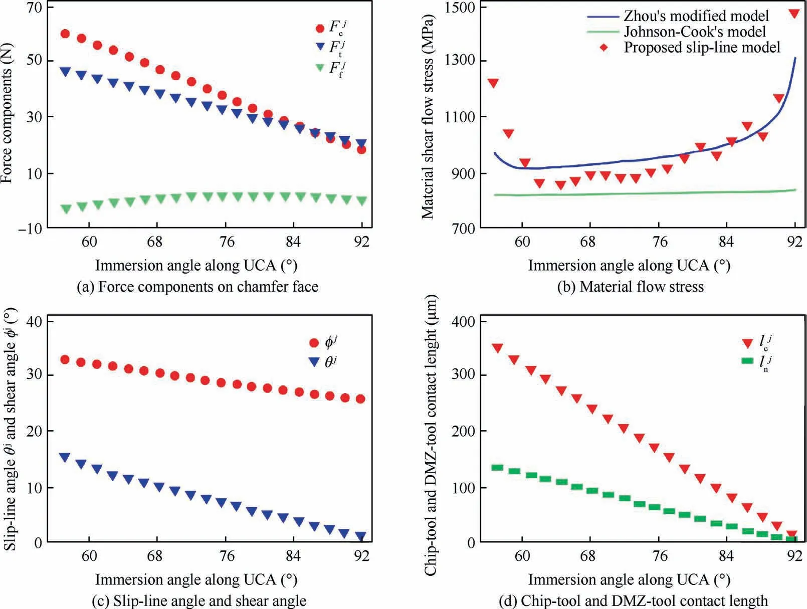
Fig. 12 Determined distributions of critical variables with variation of immersion angle along UCA.
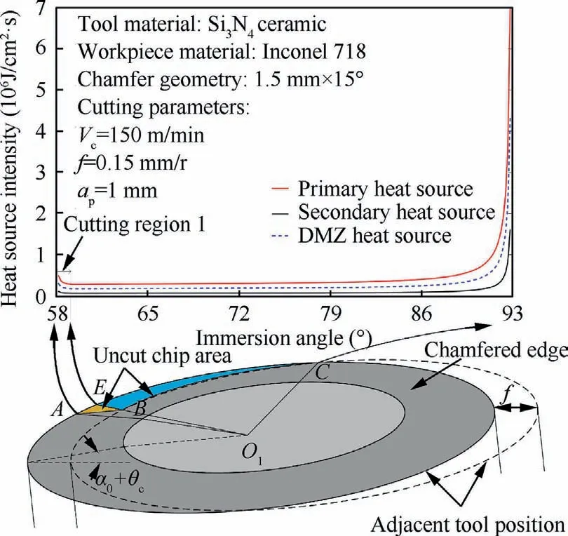
Fig.13 Intensities of heat sources in PDZ,SDZ and DMZ along cutting edge.
Fig.15 concludes all the predicted and simulated maximum interface temperatures Tmaxand the distances Dswith respect to Vc,f, apand θc. It can be observed that all the four parameters have a positive impact on Tmaxand Ds.Fig.15(a)reveals that an increment of 50 m/min in cutting speed can caused nearly 60°C temperature increase in average. The distance increases slightly with the cutting speed, which could be explained by the slight increase of DMZ-tool contact length(IE in Fig. 5). Obvious increases of both cutting temperatures and distances are found for the varying feed rates.To be specific,the temperature increased about 45°C for per 0.05 mm/rev of feed rate. It is also noticed that the trend of increase slows down when feed rate approached 0.30 mm/rev. This could be caused by the intensified thermal-softening effect when cutting temperature gets above the material melting temperature(1277°C for Inconel 71832). The tendencies of temperature increase and distance given in Fig. 15(c) where depth of cut considered is similar to that in Fig. 15(b). It denotes that the selection of apis as critical as that of feed rate for the cylindrical turning with large-chamfer round insert. Fig. 15(d) reveals that with the increase of chamfer angle, the distance grows rapidly. This is because the DMZ-tool interface (IE in Fig. 6) is significantly affected by the chamfer angle, which is consistent in tendency with our previous findings with negative-rake-angle insert.22On the contrary, the maximum interface temperature carries a really gentle increase with the increasing chamfer angle. This could be caused by the growth in cutting forces and simultaneously decrease in length of secondary heat source(SI in Fig.6).Above all,the results of both Tmaxand Dsfrom predictions show close agreement with those from the 3-D FE simulations. Moreover, the slip-line solution based thermal model is much less time-consuming when compared with the 3D FE simulation approach, which takes over sixteen hours in average for a single job on a six-core(3.2 GHz each)personal computer.Thus this analytical thermal model is capable of providing quick estimation of cutting temperature field. And it could be further applied to the establishment of online monitoring system of cutting process.
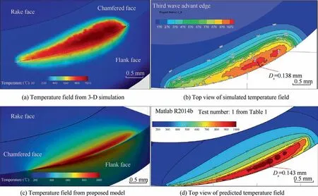
Fig. 14 Comparison of simulated and predicted temperature field.
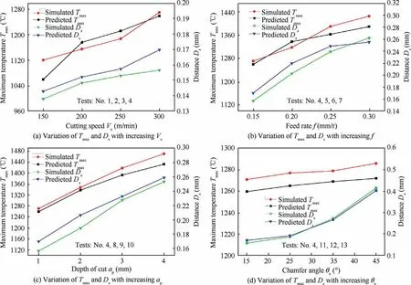
Fig. 15 Comparisons of predicted and simulated Tmax and Ds with varying cutting conditions.
4.2. Experimental validation
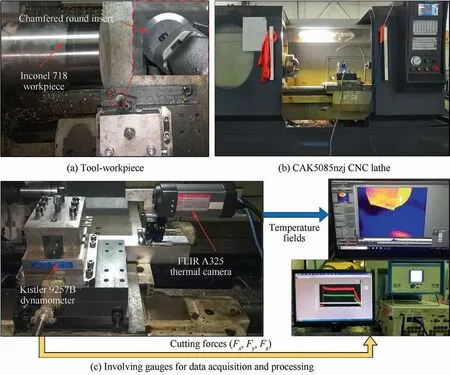
Fig. 16 Experimental setup for turning operation of Inconel 718.

Table 2 Design of cylindrical cutting tests of Inconel 718 with chamfered round insert.
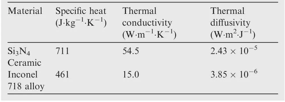
Table 3 Thermal properties of ceramic insert and Inconel 718 workpiece.
In this part, a series of cylindrical cutting tests of Inconel 718 alloy using chamfered round insert is employed to validate the practicality of the proposed temperature prediction model.The chamfered round ceramic insert utilized in the present experiment is 12.7 mm in diameter and the chamfered edge prepared with 1.5 mm length and 15°inclined angle from rake face as given in Fig.16(a).Fig.16(b)depicts the CNC lathe for the dry turning trials. The insert is then stabilized to the bulk with an initial rake angle -6°. The three-component dynamometer, Kistler 9257B is fixed to the feed box shown in Fig. 16(c). The thermal imager, FILR A325 with 406×240 LWIR resolution, is adopted for temperature recording.Corresponding measurements are obtained through the monitoring packages on computers. The design of the experimental cutting parameters is specified in Table 2.
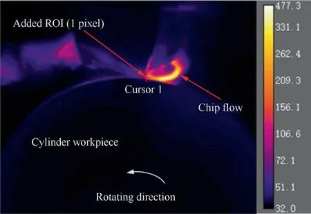
Fig. 17 Example thermal infrared image from experiments.
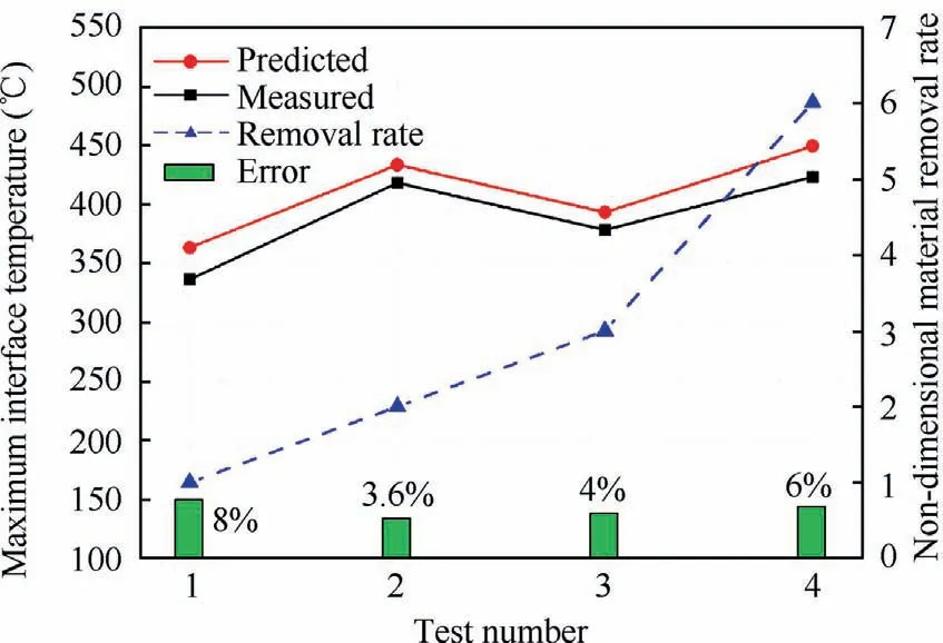
Fig. 18 Distribution of maximum interface temperatures from the measurements and predictions with theoretical material removal rate (non-dimensional).
The thermal camera has been calibrated using thermal couples before the measurement, and the emissivity of it is valued 0.95 which was also adopted by Aubrecht et al.35and Jesuraj et al.36The thermal properties of the Si3N4ceramic insert determined by Trent37and Inconel 718 workpiece by Kitagawa et al.38utilized in the proposed model are specified in Table 3.
The temperature profiles are recorded and estimated by post-process module, Research IR Max as depicted in Fig. 17, where an example thermal image of the cutting temperature fields at the chip-tool interface is provided.Appropriate region-of-interest (ROI) points are added to extract the temperature distribution at the particular region.
Fig. 18 summarizes the maximum interface temperatures from the measurements and corresponding predictions with respect to the design specified in Table 2. Close agreement can be found between the two temperature curves.The average error is lower than 10%.In addition,the temperatures increase with the increase of Vc,f,ap,which is in good accordance with the findings from 3-D FE simulations.The additional dash line depicts the theoretical material removal rates for each test,which is transmitted as a non-dimensional ratio by treating the removal rate in test 1 as unit as contrast. An interesting phenomenon is observed by comparing test 3 against test 1,that is,the material removal rate almost triples while the maximum cutting temperature only increase slightly by 20°C.Meanwhile, the temperature rises by over 60°C to double the material removal rate from test 2 against test 1. This phenomenon indicates that the condition with larger depth of cut and cutting velocity is more favorable to increase machining efficiency, than with larger feed rate.
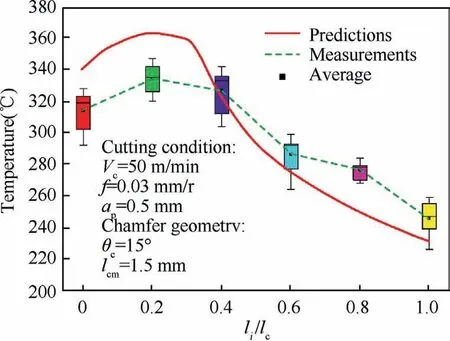
Fig. 19 Predicted and measured temperature distribution along chip flow direction.
To give a clear comparison about the temperature distribution at the chip-tool interface, the measured temperature field is then compared with the prediction from the presented thermal–mechanical model as illustrated in Fig. 19. The predicted temperature distribution is extracted along the tool-chip contact line which is forecasted to go through the region with maximum temperatures.
Fig.19 depicts that the predicted cutting temperature at the initial cutting edge area (li/lc=0)is a bit higher than the measured one. This can be ascribed to the blocking influence of chip flow during the recording of temperature profiles at the chip-tool interface. Hence, the temperature distributions detected are slightly lower than the actual maximum temperature. Furthermore, the emissivity of the materials is supposed varying apparently with the increase of the cutting temperature, which is not considered in this research for computation simplicity. In spite of those deficiencies mentioned above, the predicted temperature curves still show an encouraging match with the average experimental measurements, which validates the reasonableness and applicability of the presented 3-D analytical model for round tool with large chamfer in practical machining process.
5. Conclusions
In the present research, a novel 3-D analytical temperature prediction model based on the developed slip-line theory for chamfered round insert is presented. The contact geometries upon tool chamfered edge and associated heat sources are analyzed and determined. Results from plenty of 3-D FE simulations and experiments are compared against the predictions,where pleasant consistency is received. The contributions of this study can be concluded as following:
(1) A 3-D discretization methodology is developed to elaborate the abnormal cutting and contact geometries in cylindrical turning operation with chamfered round insert.Detailed analysis of the complicated spatial distributions of every discretized cutting element is carried out in both radial and chip flow directions in a Cartesian coordinate system.
(2) A slip-line solution is applied to the determination of local shear flow stresses and material flow velocities adjacent to tool edge.Intensities of heat sources and corresponding geometries in PDZ, SDZ and DMZ for every discretized cutting element are computed through the proposed model.
(3) A 3-D temperature prediction model for chamfered round insert is proposed analytically by means of the modified slip-line field solution and imaginary heat source approaches.The resulting temperature rise distributions due to heat generation in PDZ, SDZ and DMZ apart from associated imaginary heat sources are becoming computable with the proposed model. The determined temperature distributions indicate that the region with maximum temperature values is actually existed upon the chip-tool interface instead of the tool edge.
(4) The rationalities of cutting parameters are analyzed with corresponding material removal rates and maximum interface temperatures.Theresults indicatethat the cutting conditions with large depth of cut and high cutting speed are more desirable than those with high feed rates.This finding may provide effective guidance of optimal cutting parameters for cutting with large-chamfer round insert.
Declaration of Competing Interest
The authors declare that they have no known competing financial interests or personal relationships that could have appeared to influence the work reported in this paper.
Acknowledgements
This work is partially supported by the National Natural Science Foundation of China (No. 51705385), the National Defense Pre-Research Foundation of China (No.61400020108) and the Excellent Dissertation Cultivation Funds of Wuhan University of Technology of China (No.2018-YS-034).
 CHINESE JOURNAL OF AERONAUTICS2021年10期
- CHINESE JOURNAL OF AERONAUTICS的其它文章
- Direct dynamic-simulation approach to trajectory optimization
- A strong robustness open-circuit fault diagnosis strategy for novel fault-tolerant electric drive system based on d-q-axis current signal
- Nonlinear vibration response characteristics of a dual-rotor-bearing system with squeeze film damper
- Ground maneuver for front-wheel drive aircraft via deep reinforcement learning
- Numerical simulation of a UAV impacting engine fan blades
- Recent advances in precision measurement &pointing control of spacecraft
