Experimental study on impact of roller imbalance on cage stability
Yongun CUI, Sier DENG, Kaiwen DENG, Hui LIAO,Wenhu ZHANG
a School of Information Engineering, Henan University of Science and Technology, Luoyang 471003, China
b Post-Doctoral Workstation, Bahuan Technology Group Co., Ltd, Taizhou 318000, China
c School of Mechatronics Engineering, Henan University of Science and Technology, Luoyang 471003, China
d School of Mechanical Engineering, Northwestern Polytechnical University, Xi’an 710071, China
KEYWORDS Cage orbits;Cage stability;Experimental study;High-speed cylindrical roller bearing;Roller imbalance;Spectrum;Vibration
Abstract This study presents a method for measuring the imbalance in a small-sized cylindrical roller. The roller imbalance was calibrated on the built static-pressure-air flotation measurement machine. The impact of the roller imbalance on the dynamic characteristics of a cage were then studied on the aero-bearing test rig. The displacement spectrums with different roller imbalance of the obtained cage orbits under various bearing speed and radial load were used to evaluate the cage stability. The results show that the cage cannot form a stable operating state at a lower bearing speed with or without the unbalanced rollers. The cage with balanced rollers gradually develops stable motion with the increase of the bearing speed.The existence of a small roller imbalance causes the stability of the cage to deteriorate.With an increase in the bearing speed and radial load,the cage with the unbalanced rollers runs unsteadily accompanied by a high-frequency vibration when the roller imbalance is large enough.The vibration amplitude of the cage in the horizontal direction is greater than that in the vertical direction during an unstable operation, which is similar in the stable status.
1. Introduction
High-speed cylindrical roller bearings are widely used for the main shaft in an aero-engine. The dynamic characteristics of bearings have an important influence on the performance of the aero-engine. Roller imbalance (mass (g)∙distance (mm)) is introduced by the roller mass center that does not coincide with its geometric center due to various factors such as the in-uniformity of the material, roller profile deviation, chamfer errors at the ends of the roller,uneven wear at both ends in the application, etc. During bearing operation, the additional forces and torques produced by roller imbalance can affect the cage dynamic characteristics.1–3Therefore,in order to verify the influence of the roller imbalance on cage dynamic characteristics in high-speed cylindrical roller bearing, an experimental research is carried out in this paper.
The dynamic characteristics of rolling bearing have always been a research focus. In 1985, Gupta et al.4compared the cage motions of an angular contact ball bearings obtained through computer models with those obtained experimentally.Both the computer predictions and experimental data indicate that when the shaft reaches a certain critical speed, the cage mass center begins to whirl. Additionally, the whirl velocities and orbit shapes are in good agreement. Boesiger et al.5studied the dynamic instability of ball retainers in precision bearings and identified the key features by experiments. The retainer instability is found to be highly sensitive to the retainer-ball friction and exhibited a constant characteristic frequency,which is independent of the bearing speed,external vibration, radial load, and preload. Selvaraj and Marappan6developed a cylindrical roller bearing test rig and studied the effect of the operating parameters such as the shaft speed,radial load,lubricant viscosity,number of rollers,and bearing temperature on the cage slip ratio. Madoliat and Ghanati7concentrated on theoretical and experimental non-linear stiffness studies of the spindle angular contact ball bearing of a milling machine tool. The results of the developed theoretical model closely match with the experiment data. Prakash et al.8investigated the vibration suppression characteristics of ball bearing supplied with nano-copper oxide (CuO) mixed lubricant.The results show a reduction of 41%vibration amplitude while using 0.2%(w/v)CuO nanoparticles in outer ring defect compared to base lubricant.French and Hannon9summarized the mechanics governing spall propagation and experimentally studied two angular contact ball bearings, one with a seeded fault and the other fault-free.The results show that the impact event is evident in the accelerometer response and the strain gauge response, provided the gauge is in the spall vicinity. Li et al.10built a spindle test system with adjustable nonuniform distribution preload and analyzed the spindle performances with rolling bearing under non-uniform preload through experiments. Abele and Holland11proposed an image-based approach for investigating the cage motion,window-type cage under operation conditions, and the cage center movement behavior with different accelerations. Wen et al.12experimentally investigated the cage dynamic motions under various rotating speeds and external loads in a ball bearing. The measure data were analyzed by fast Fourier transform (FFT) and compared at different operating conditions including rotating speeds, axial and radial forces, and moments. Han et al.13investigated how cage motions was affected by its unbalance,both theoretically and experimentally. The results show that the increment of cage unbalance mass makes the trajectories of cage center more regular and the whirl radii larger;the wear extent of cage guiding surface increases with the increment of cage unbalance. Wang et al.14studied the effects of flywheel dynamic/static eccentricities, inner/outer surface waviness amplitudes,bearing axial preload,and installation skew angles on the dynamic output torques of bearings. Choe et al.15,16experimentally studied the dynamic charismatics of ball bearing cage in cryogenic environments. The results include the effects of cage guidance, pocket clearances, and the cage mass imbalance on the cage stability.
Many more scholars have also studied the bearing dynamic performances by means of theoretical analysis. Niu et al.17investigated the stable cage whirl in ball bearing with outer ring guided cage under solid lubrication conditions through the dynamic simulation.Zhang et al.18,19investigated the influence of the lubricant traction coefficient on the non-linear dynamic behavior of the cage. The results show that the type of aviation lubricating oil is selected according to the different working conditions of the rolling bearing. Nogi et al.20developed a simple theory on cage instability and proposed a critical cage friction coefficient formula. On this basis, the cage dynamic behavior of the ball bearings was investigated. In summary, many researchers have done significant work about the cage dynamic characteristics. However, few researchers have experimentally explored the impact of roller imbalance on cage dynamic stability in high-speed cylindrical roller bearings.
In this study,the imbalance value of the roller is calibrated on the measuring machine,and the cage motions are measured on the aero-bearing test rig.The orbits of the cage are collected at various operating conditions including the roller imbalance,the bearing speed, and radial load. The frequency spectrums are obtained with FFT.Finally,the impact of the roller imbalance on the cage stability is discussed.The research results can provide some theoretical principles for designing and manufacturing high-speed cylindrical roller bearing.
2. Test rig setup
2.1. Roller imbalance test
2.1.1. Test theory
Assuming the roller angular velocity is ωr, and the roller imbalance is expressed as U, the vibration response equation of the roller can be expressed as
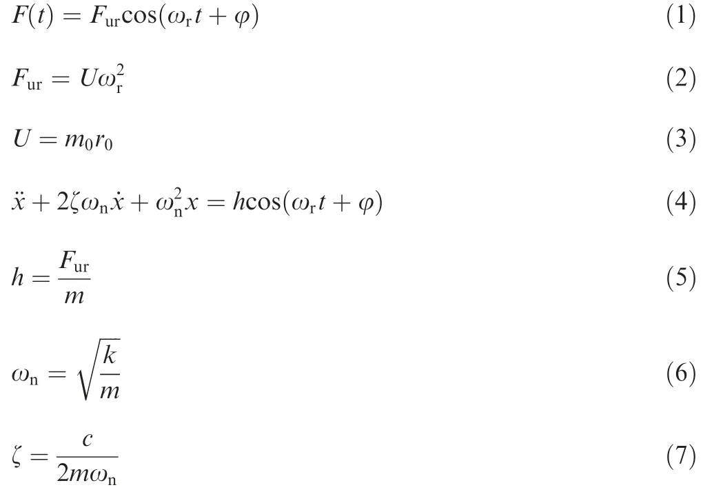
where F(t) is the exciting force, m0is the eccentric mass, r0is the eccentric radius, Furis the force generated by roller imbalance, m is the sum masses of the roller and the air flotation table,k is the stiffness of workbench,c is the damping of workbench, and φ is the initial phase.
By solving the vibration response equation, the homogeneous solution of the equation can be obtained as
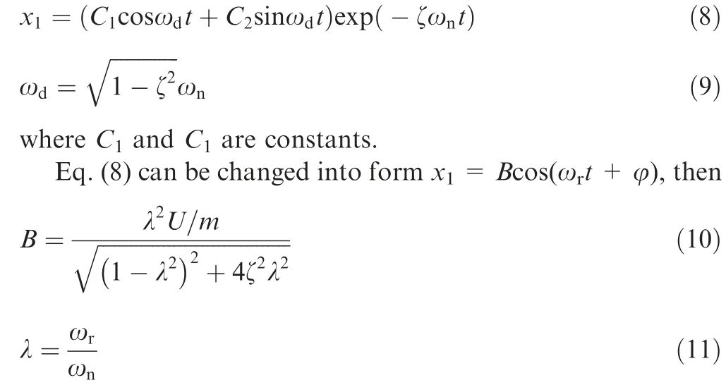
where λ is the ratio of the vibration frequency of the unbalanced roller to the natural frequency of the air flotation table.When λ ≈1, resonance occurs and the vibration amplitude of air flotation table is the largest. The amplitude of the resonance can be extracted by amplifying vibration response.
Based on this principle, a static-pressure-air flotation measurement machine for calibrating the small-sized cylindrical roller imbalance was built. The system schematic diagram is shown in Fig. 1.
2.1.2. Test procedures
First, the test roller was adsorbed on the air spindle probe of by negative pressure. Once the set speed was reached, the test roller was separated from the probe and suspended in the static air flotation cavity. Because there was no contact between the roller and the cavity in the measurement process,the test roller continued rotating because of its inertia. The excitation produced by the roller imbalance caused the high-rigidity air flotation table to generate vibration displacement. The vibration signal was measured by the laser sensor and transmitted to the acquisition device, and then the imbalance value was converted to the amount of imbalance.Thus, the imbalance value of the test roller can be obtained by the test machine with zero external interference. The main components of the measurement machine are shown in Fig. 2.
The average imbalance value of the test roller was recorded with a series of tests,which were prepared for investigating the impact of roller imbalance on the cage dynamic stable characteristics. Table 1 shows the five different levels of roller imbalance selected.
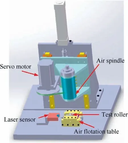
Fig. 1 Schematic diagram of roller imbalance measurement machine.
2.2. Cage dynamic characteristics test
2.2.1. Test rig
Fig. 3 shows the main components of the cage dynamic characteristics test rig. They include a main body, an electric spindle, a lubrication system, a hydraulic loading system, an electrical system, and a computer monitoring system. The main body of the test rig was mounted on a cast iron base.Different speed conditions can be achieved with the inverters, the electric spindle and electrical measurement, and the control system. The hydraulic loading system provides the load for the test system and simulates the actual working load of the test bearing. The lubrication system provides lubrication for the test bearings and accompanied bearings.The working temperature of the test bearings was achieved by heating the lubricating oil, which can also be used for the cooling of the bearings. Recording and processing of the experimental data were achieved through a data acquisition system.The monitoring system can monitor all test procedures to ensure the proper operation of the test rig.
2.2.2. Measuring principles of cage orbit
The inner and outer ring of the test bearing were fixed on the shaft and busing, respectively. The rotation of the shaft was driven by a high-speed motor spindle through the coupling.The cage and rollers have six degrees of freedom. Fig. 4 illustrates the schematic diagram of the installation of the cage displacement measurement sensors, which were installed on the outer ring busing. The displacements of the cage in the radial plane were measured by two mutually perpendicular noncontact eddy current displacement sensors. The displacements in the vertical direction(Y direction)and the horizontal direction(Z direction) were obtained by sensor SQ3 and SQ4 respectively. Three additional eddy current displacement sensors,defined as SQ1,SQ2,and SQ5 were installed in the axial position to measure the skew angle and the axial displacements of the cage. To avoid the interference of the sensors on the normal operation of the bearing, the gaps between the probes and the cage are set to 0.65 mm for all the tests. Fig. 5 shows the internal structure of the bearing box.
2.2.3. Test procedures
Fig.6 shows the disassembly diagram of the test bearing.Special grinding process was adopted for the roller chamfers. In addition to the test roller, others were all grade I precision rollers which can be considered as balanced.It was necessary to replace the full set of rollers in the bearing and use the same group of rollers to ensure identical bearing radial clearance and the cage pocket clearance in the test. To reduce the interference of the external factors and ensure the accuracy of the results,extreme conditions were selected and only one unbalanced roller was replaced in each test,and the other rollers were regarded as ideal or balanced because of the negligible effect of small imbalance at lower speeds. The main parameters of the sample high-speed cylindrical roller bearing are listed in Table 2.
To eliminate the axial clearance of the supporting bearings while reducing the influence of the shaft imbalance and increasing the shaft stiffness, a predefined axial load was applied to the main shaft according to the structural design features of the test rig. Before the measurements were taken,the test rig would be run-in to ensure that the speed, temperature, and displacement signals were stable (20 min or so). The axial load was set to 1200 N,and the test curves and data were saved every 30 s during each test.The experimental conditions are listed in Table 3.
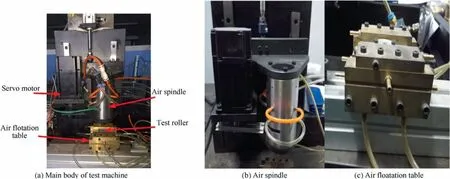
Fig. 2 Main components of roller imbalance measurement machine.
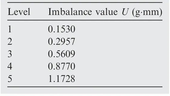
Table 1 Five different levels of roller imbalance.
3. Results and discussions
3.1. Analysis of the cage stability in the results under different bearing speed
After the conditions listed in Table 3 were set, the cage movements at 5 different speeds(1500,3000,4500,6000,7500 r/min with the radial load of 600 N) were analyzed under constant conditions.
Fig. 7 shows the cage orbits and frequency spectrums at a bearing speed of 1500 r/min.Whether or not there is an unbalanced roller,the cage orbits still show erratic status.Additionally,the multiple peaks and non-integer frequency components appear in the corresponding spectrums. When the bearing operates at a low speed, there is no stable drag film between the rollers and the rings.It is challenging to form a stable coupling motion between the cage and rollers thus the cage operation is unstable. In addition, the vibration amplitude of the cage in the horizontal direction (Z direction) is significantly larger than that in the vertical direction (Y direction) at the same frequency. This means that the cage mainly maintains horizontal movement.
When the bearing speed increases to 3000 r/min, a stable coupling operation gradually forms between balanced rollers and the cage, as depicted in Fig. 8(a). The peak amplitude of the vibration at fc(fcis the cage vortex frequency)is significant.Its multiple frequencies 2fcand 3fcappear in the frequency spectrum. At the time, the vibration amplitude of the cage in the vertical direction is larger than that in the horizontal direction under the same frequency. However, the cage with the unbalanced rollers is in the erratic status,and the multiple frequency and the non-integer frequency components also appear in the corresponding frequency spectrums of the cage,as illustrated in Fig. 8(b)–(d).
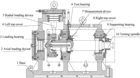
Fig. 3 Main components of cage dynamic characteristics test rig.
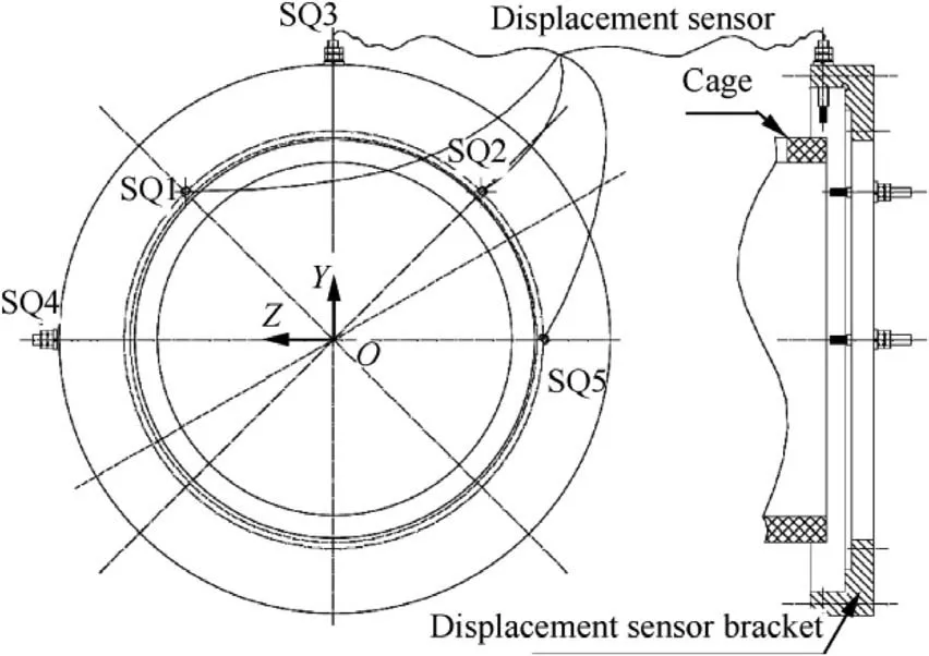
Fig. 4 Schematic diagram of installation of sensors.
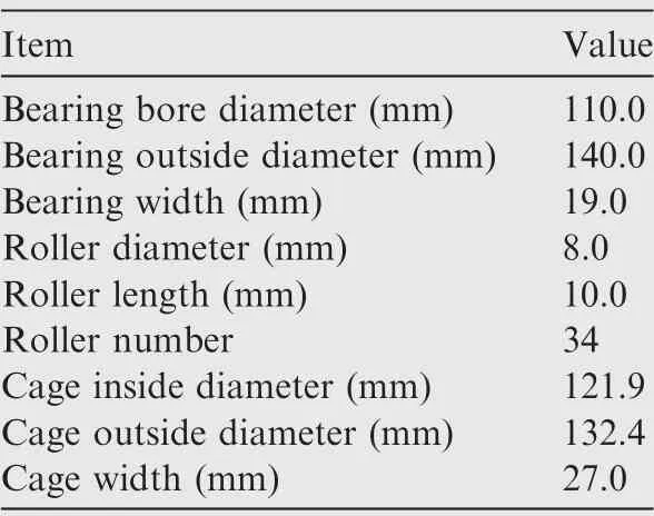
Table 2 Main parameters of test bearing.
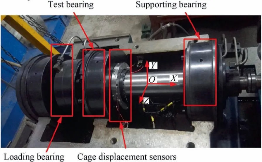
Fig. 5 Internal structures of bearing box.
Figs.9 and 10 show the bearing speed from 4500 r/min continually increasing to 6000 r/min, the cage with balanced rollers achieves a stable operation state, and the vibration amplitude of 2fcand 3fcgradually disappear. However, due to the dynamic load generated by the imbalance increases with the speed increases, the external excitation causing the cage with unbalanced rollers to produce higher-order frequency components such as 3fc, 4fc, and 5fc. This is because the influence of the external excitation produced by imbalances on thecage is greater than the coupling effect between the cage and rollers. Therefore, the cage is unable to maintain a stable operation.
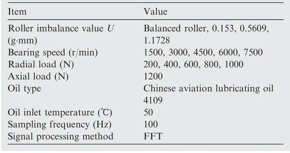
Table 3 Experimental conditions.

Fig. 6 Disassembly diagram of test bearing.
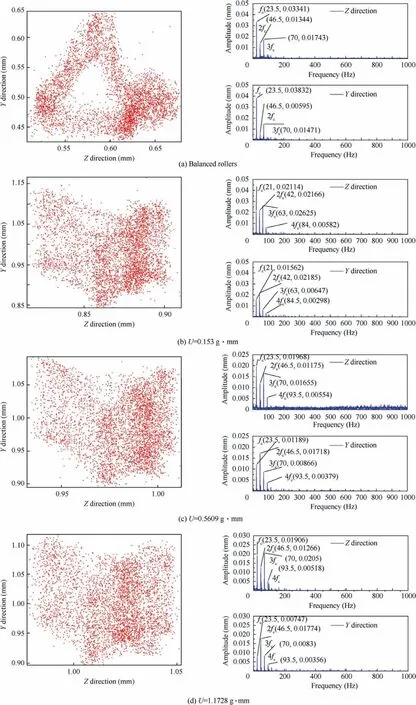
Fig. 7 Orbits and frequency spectrums of cage at bearing speed 1500 r/min.
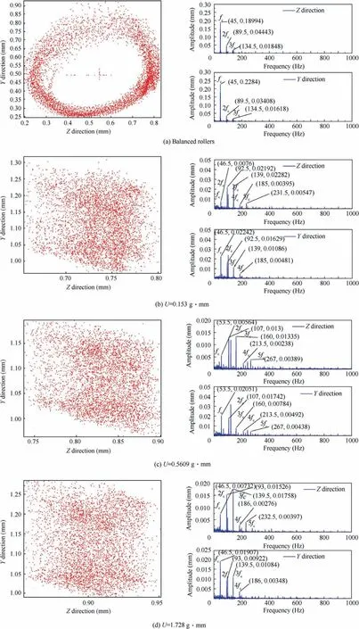
Fig. 8 Orbits and frequency spectrums of cage at bearing speed 3000 r/min.
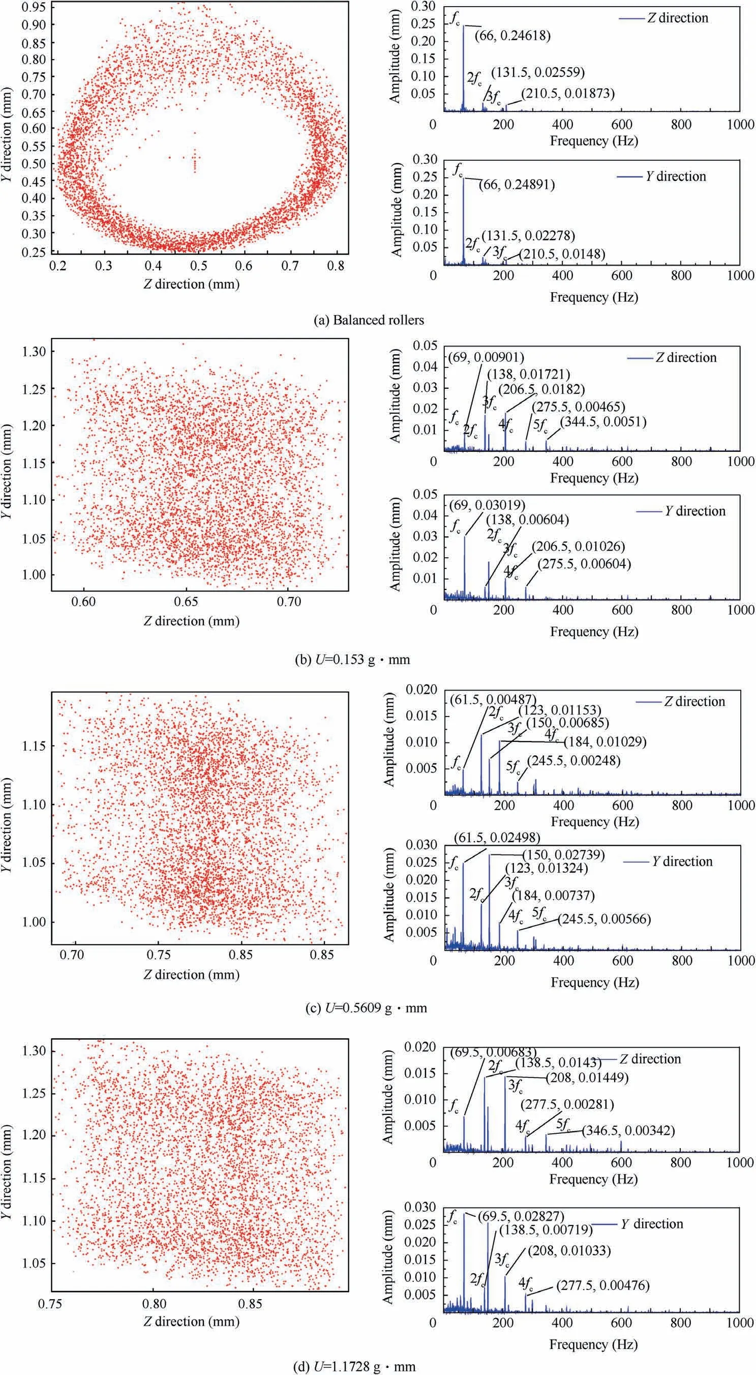
Fig. 9 Orbits and frequency spectrums of cage at bearing speed 4500 r/min.
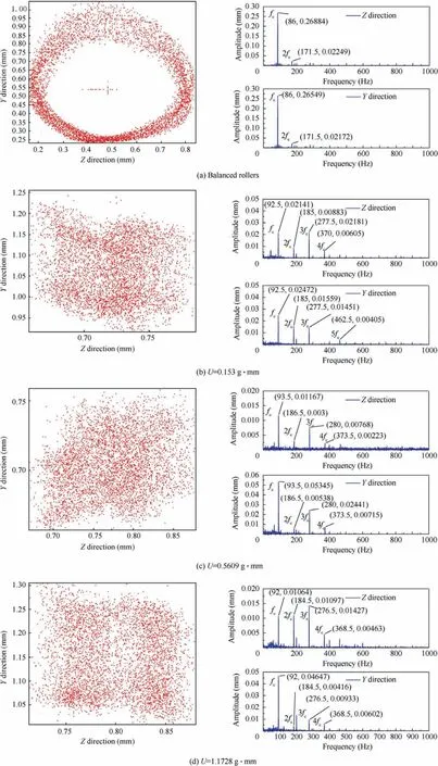
Fig. 10 Orbits and frequency spectrums of cage at bearing speed 6000 r/min.
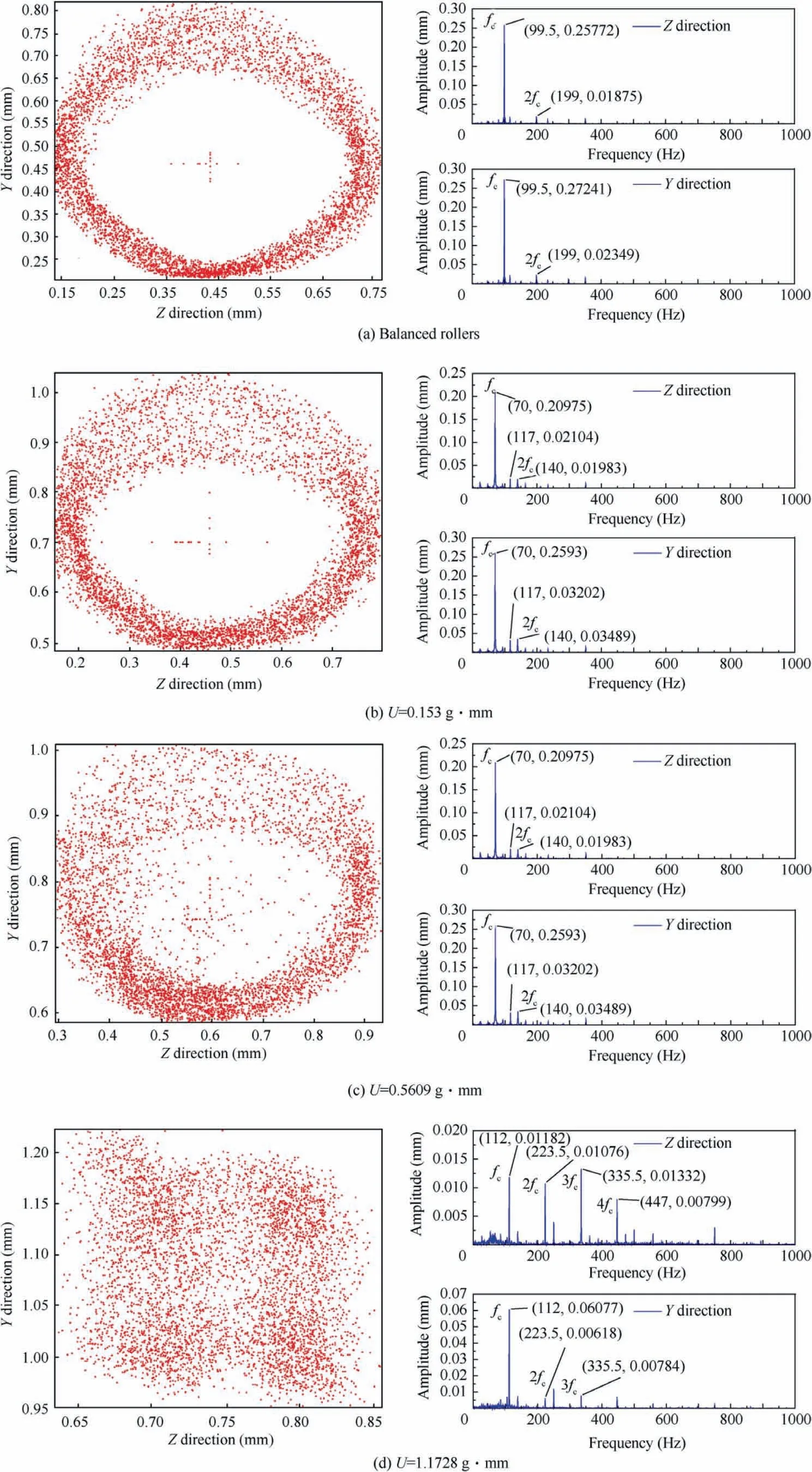
Fig. 15 Orbits and frequency spectrums of cage at radial load 800 N.
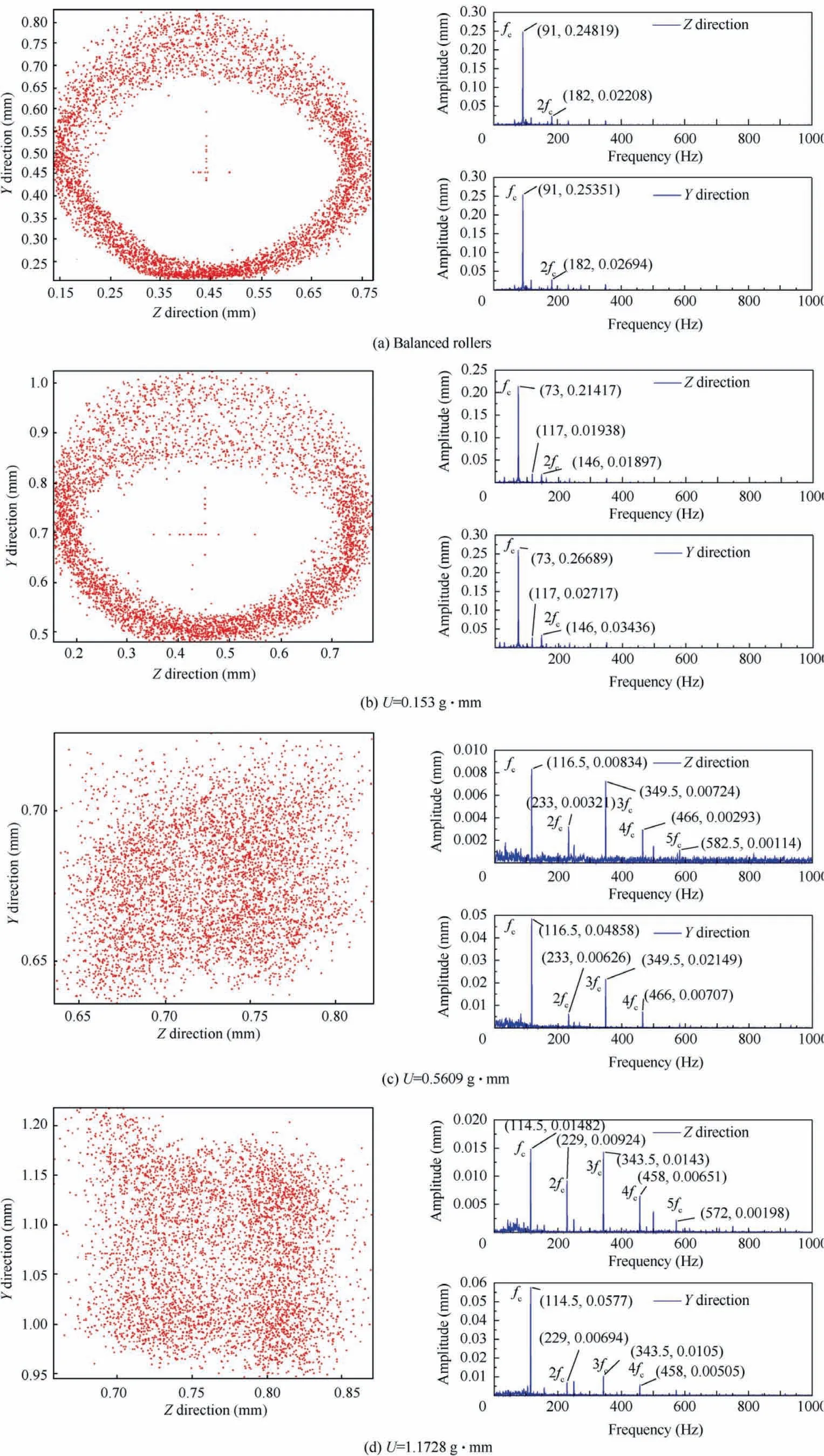
Fig. 16 Orbits and frequency spectrums of cage at radial load 1000 N.
As the bearing speed increases to 7500 r/min,the cage orbit with balanced rollers became a well-defined whirl, and the peak amplitude of the frequency in the spectrum is the vortex frequency fc.Meanwhile,the vibration amplitude of the cage in the horizontal direction is approximately the same as the amplitude in the vertical direction under the same frequency,indicating that the cage operates in a stable status, as shown in Fig.11(a).Fig.11(b)and(c)show the orbits and spectrums of the cage with roller imbalances of 0.153 g∙mm, and 0.5609 g∙mm.Although the additional dynamic load generated by the roller imbalance increases with the increase of the bearing speed, the cage and rollers can easily form a strong coupling effect as the speed increases. The additional excitation generated by the imbalance is insufficient to completely change the cage operation status;the cage can perform a stable movement. However, it can be seen from the cage orbits that the fluctuation of cage movement increases as the imbalance increases. The cage orbits with unbalanced rollers are wider than those with balanced rollers. In addition, the vibration amplitude of the cage in the vertical direction is higher than that in the horizontal direction under the same frequency.Fig. 11(d) shows the cage orbit and spectrum as the roller imbalance increases to 1.1728 g∙mm. The cage movement is very unstable. The higher-order frequency components such as 3fc, 4fc, and 5fcoccur in the corresponding frequency spectrum as well as the non-integer frequency components. This is due to the increase of external excitation produced by the roller imbalance, which causes the cage and rollers to lose a stable coupled motion; thus, the fluctuation of the cage increases.
3.2. Analysis of the cage stability under different radial load
The cage movements for 5 different radial loads(200,400,600,800, and 1000 N with the bearing speed of 7500 r/min) were analyzed under constant conditions.
Fig. 12(a) shows the orbit and frequency spectrum of the cage with balanced rollers. It can be observed that the cage can achieve a stable coupling operation and the orbit is a well-defined whirl. The peak amplitude of the frequency in the spectrum is that of the vortex frequency fc. The amplitude of 2fcis significantly smaller than the main frequency.In addition, the vibration amplitude of the cage in the vertical direction is approximately the same as that in the horizontal direction under the same frequency. Therefore, the cage is in a stable status. Under the same experimental conditions, the cage can acquire stable motion when the roller imbalances are 0.153 g∙mm, 0.5609 g∙mm, and 1.1728 g∙mm, as illustrated in Fig. 12(b)–(d). However, in the frequency spectrums of the cage, the difference between the amplitudes in the horizontal and vertical directions gradually increase at the same frequency, and the maximum amplitude of the cage is in the vertical direction.
Fig.13 presents the cage orbits and frequency spectrums as the radial load increases to 400 N.From Fig.13(a)–(c),the cage with balanced rollers,as well as the cage with roller imbalances 0.153 g∙mm, and 0.5609 g∙mm mainly keep a stable whirl motion. As shown in Fig. 13(d), the cage with the imbalance of 1.1728 g∙mm is in erratic status.The higher-order frequency components such as 3fc,4fc,5fc,and the non-integer frequency components appear in the corresponding frequency spectrum.
Figs. 14 and 15 show cage orbits and the frequency spectrums as the radial load increases from 600 N to 800 N.There is no significant change in the cage orbits with balanced rollers nor in the cage with a roller imbalance of 0.153 g∙mm. However,both the cage instability and the amplitude of 2fcincrease as the roller imbalance increases at 0.5609 g∙mm. The cage with the imbalance of 1.1728 g∙mm is in erratic status.
Fig. 16 shows the cage orbits and frequency spectrums when the radial load increases to 1000 N. The cage with balanced rollers operates in a stable whirl status, as shown in Fig. 16(a). Compared with lower loads, the amplitude of fcdoes not change, but the amplitude of 2fcincreases. The cage with a roller imbalance of 0.153 g∙mm maintains a stable whirl motion, as shown in Fig. 16(b). However, it is difficult for the cage to form stable operation with a roller imbalance of 0.5609 g∙mm, and 1.1728 g∙mm, as revealed in Fig. 16(c) and(d). Cage orbits are discrete and irregular. Higher-order frequency components such as 3fc, and 4fcas well as the noninteger components in the spectrums, especially the amplitude of 5fc, appear in the spectrum of the horizontal direction. The cage produces a high frequency vibration in the bearing and runs in a very unstable status.
3.3. Discussions
In practice,roller imbalance is discrete and random.Thus,it is challenging to conduct experiments in full accordance with the actual practical situation. The following factors may cause errors in the test:(1)Imbalance is present in the roller regarded as an ideal roller. In addition, cage imbalance cannot be avoided even though the dynamic balance has been achieved.The influence of these factors can be reflected in the cage orbits and spectrums. (2) The inevitable errors of the test rig such as the vibration of the motorized spindle, installation errors, displacement sensors measurement accuracy errors, and the vibration of the sensors which are installed on the tooling,affect test results.However,these factors do not affect the reliability and reference value of the test results.
4. Conclusions
(1) The cage cannot acquire a stable status at a lower bearing speed despite the cage containing an unbalanced roller. When the bearing speed increases, the cage with balanced rollers achieves a stable motion.
(2) When the cage contains unbalanced rollers,the existence of a smaller roller imbalance causes the stability of the cage to deteriorate. With the increase of bearing speed,the cage with unbalanced rollers runs unsteadily,accompanied with high-frequency vibration when roller imbalance is large enough.
(3) The vibration amplitude of the cage in the horizontal direction is significantly larger than that in the vertical direction during unstable operation and the cage is dominated by the horizontal movement. The amplitude in the horizontal direction is equivalent to that in the vertical direction when the cage operates in a stable whirl.
(4) The radial load has little effect on the running state of the cage with balanced rollers. However, the cage with a bigger roller imbalance runs in an unstable status under a larger radial load.
Declaration of Competing Interest
The authors declare that they have no known competing financial interests or personal relationships that could have appeared to influence the work reported in this paper.
Acknowledgement
This work was supported by the National Science Foundation for Young Scientists of China (No. 51905152).
 CHINESE JOURNAL OF AERONAUTICS2021年10期
- CHINESE JOURNAL OF AERONAUTICS的其它文章
- Direct dynamic-simulation approach to trajectory optimization
- A strong robustness open-circuit fault diagnosis strategy for novel fault-tolerant electric drive system based on d-q-axis current signal
- Nonlinear vibration response characteristics of a dual-rotor-bearing system with squeeze film damper
- Ground maneuver for front-wheel drive aircraft via deep reinforcement learning
- Numerical simulation of a UAV impacting engine fan blades
- Recent advances in precision measurement &pointing control of spacecraft
