Optimization and analysis of composite sandwich box beam for solar drones
Liang ZHANG, Dongli MA, Muqing YANG, Xinglu XIA, Yuan YAO
School of Aeronautic Science and Engineering, Beihang University, Beijing 100083, China
KEYWORDS Buckling analysis;Low-order analytical method;Multi-stage optimization;Sandwich box beam;Solar drones
Abstract Solar drones have garnered considerably research attention in recent years due to their continuous cruising capability, and the feasibility of design schemes is sensitive to the weight of structure. Sandwich box beam composed of carbon fiber and polymethacrylimide (PMI) foam is conducive to realize the lightweight of structure. In this study, a two-stage optimization design methodology for sandwich box beam is proposed. This methodology is primarily based on a low-order analytical method for evaluating stress/deflection and the linear buckling analysis method combined with experimental correction factor for predicting the buckling eigenvalues. Subsequently, a case study was conducted using an 18-m wingspan solar drone, where the results of mechanical test verified the optimization results. For validating the use of sandwich box beam in solar drones of other scales, additional analysis was conducted based on three aspects: (A) effects of stiffness and stability constraints on the design of sandwich box beam; (B) crucial role of the weight of foam inter layer and application scope of sandwich box beam;(C)best method to improve the buckling eigenvalue of sandwich box beam. Overall, the methodology and general rules presented in this paper can support the design of light wing beam for solar drones.
1. Introduction
Solar drones with ultra-long endurance break the technical bottleneck of uninterrupted flight in principle and have become a major research hotspot in recent years.1–3However,the unique layout and mission characteristics of solar drones imposes several requirements for realizing lightweight and reliable structural design.4To reduce the induced drag, solar drones are usually designed with wing of large Aspect Ratio(AR). Moreover, the feasibility of the design scheme is highly sensitive to the total weight.5According,the wing should exhibit maximum specific strength and stiffness. In terms of structural design, solar drones usually employ flexible materials as skin and rely on the wing beam to provide the bearing capacity,which generally simplifies the secondary structures such as fuselage and landing gear.6Therefore,wing beam is one of the primary components of solar drone structure.
Presently, solar drones mostly contain thin-walled wing beams made of composite materials of carbon fiber.7They usually have two types of cross sections,circular and rectangular,which are capable of withstanding bending moment and torque. For instance, ‘‘Zephyr” series drones8and ‘‘Helios”drone9use circular section beams, while ‘‘X-HALE” drone10and‘‘Solar Impulse”manned aircraft11use rectangular section beams.Compared with circular section beam,despite the complexity of the process, the rectangular section beam has a higher bending section coefficient, which can give full play to the fiber properties on the flange.
Rectangular thin-walled beams,also known as‘‘thin-walled box beams”, have a mature technical system. Herakovich12introduced stress calculation method of composite laminated plate and derived strength checking method for laminated plate thin-walled box beam. Tarjan et al.13summarized the buckling load estimation methods and provided the corresponding empirical formulas for laminated plate beams under different boundary conditions and load distributions.Montagnier and Bovet14considered critical load failure condition and used analytical mass equation to minimize the number of plies in wing box. Alsahlani et al.15combined the theory of Herakovich and Tarjan and proposed a low-order estimation method for thin-walled box beam of solar drones.This method quickly optimized the composite layer of laminated plate box beam and minimized the weight of the structure. Cao and Ou16analyzed the strength, rigidity, and stability of a thinwalled box beam under various loading and reinforcement conditions by using Finite Element Method (FEM). Further,they analyzed the main mechanical characteristics of the thin-walled box beam.
All the above studies discussed the applicability of box beam in solar drones, but they were limited to laminated box beam. However, compared to conventional aircraft, the wing load of solar drone is generally low, and the wall thickness of the box beam designed to meet the strength and stiffness constraints is usually small, which makes structural buckling an important factor to be considered.It has been reported that sandwich structure can provide significant improvement in structural stability with less weight cost than laminated structure, such as the honeycomb sandwich structure, which has been widely used in conventional aircrafts.17,18The density of polymethacrylimide (PMI) is similar to that of honeycomb material, but it exhibits higher specific strength and stiffness.In addition, PMI has isotropy and good machinability, which can effectively restrain local buckling.19Xu et al.20investigated the sandwich structure by FEM, and found that the carbon fiber reinforced triangular grid was much stiffer than the honeycomb structure. Rahmani et al.21and Boussoula et al.22carried out bending analysis of sandwich plates based on the high-order deformation theory with only four unknowns in the displacement field, which made the analysis model more simple to use.Irfan and Siddiqui et al.23summarized the recent research progress on the finite element formulation of sandwich plates and analyzed the buckling phenomenon. Chikr et al.24and Refrafi et al.25studied the buckling response of sandwich plates based on the new shear deformation theory,which guarantees the accuracy of the predicted results without using any shear correction factors.Based on this,the effects of geometric and environmental parameters on the buckling response are studied. In terms of design process, multi-stage optimization is widely used in composite structure design.Hao et al.26.27developed a multi-stage design method for variable stiffness panels based on lamination parameters to overcome the problem caused by the nonlinearity and non-convexity of this structure, and proposed an integrated framework of exact modeling, isogeometric analysis and optimization for variable-stiffness panels for the global optimum.The authors also presented a hybrid multi-stage framework for reliability-based design optimization of stiffened shells,28and in the above processes,the multi-stage optimization design method all made contributions in saving the computational cost and improving the accuracy.
According to the above studies,a sandwich box beam composed of carbon fiber and PMI foam has immense potential in the field of solar drones.However,the application of sandwich box beam to solar drones with ultra-long-endurance has been rarely investigated. The unique aerodynamic layout of solar drones and the special buckling analysis method of sandwich structure both lead to the particularity of design method and application law. In this study, we propose a two-stage optimization design methodology for sandwich box beam,and successfully applied this method to an 18 m-wingspan solar drone in practice.Further,we analyze the design law for such beams to promote the application of sandwich box beam in solar drones of all scales.Given the scale of a solar drone,this paper can help guide the optimization design of the sandwich box beam, judge the applicability of sandwich structure, and qualitatively analyze the impact of different boundary constraints in the design process.
This paper consists of four parts. In Section 2, the design framework of sandwich box beam for solar drones including design object, design goal, and constraints is established. The optimization design process is discussed in Section 3, which includes low-order stress/deflection calculation method and estimation method for buckling eigenvalue based on linear buckling analysis and experimental correction. In Section 4,the design and manufacturing process of sandwich box beam for an 18-m wingspan solar drone is presented, and the design results are compared with that for a laminated box beam. In Section 5,the feasibility of the proposed scheme is investigated for solar drones of other scales.The effects of stiffness and stability constraints on the design are studied,and the application range of sandwich box beams is explored. Furthermore, the sensitivity of buckling eigenvalues to design parameters is examined. The results provide a universal reference to design light and reliable wing beams for solar drones.
2. Design framework
2.1. Typical structure of sandwich box beam
The typical structures of wing and sandwich box beam in a solar drone are shown in Fig.1.The beam is the main bearing component of the wing,and it is located one third of the chord from the leading edge of the wing, passing through ribs.
The sandwich box beam is machined by fabric wrapping instead of filament winding to ensure the convenience of the process and the balance of the structure. When the fabric orientation changes from±45° to 0°/90°, the bending rigidity of the box beam increases,while the torsional rigidity decreases.12However,it is obvious that the 0°layer in the flange will bring higher benefits to the bending rigidity,so the fabric orientation is set to a fixed parameter of±45°to bear the shear force and torque, and a similar setting is adopted in Ref. [15].
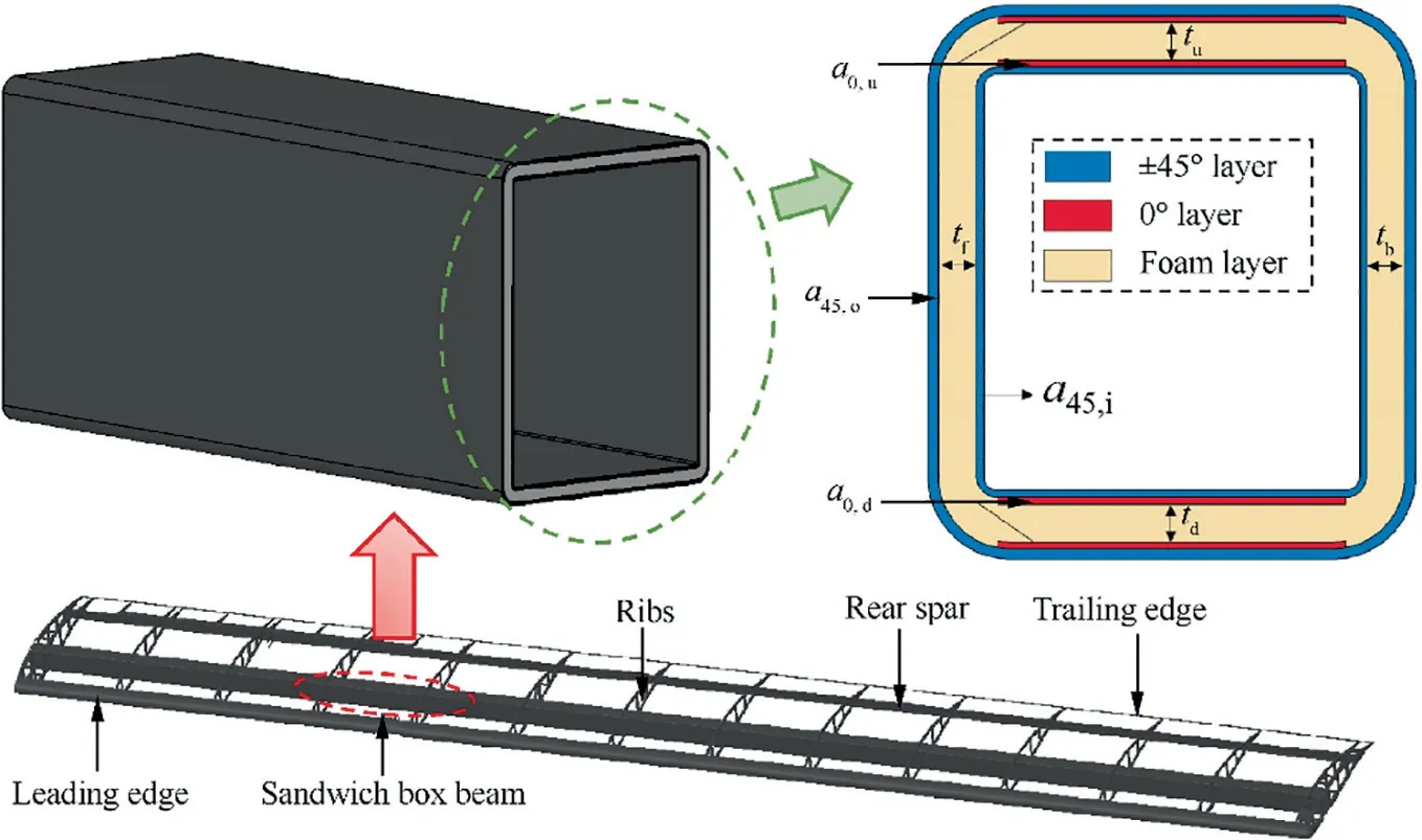
Fig. 1 Composite sandwich box beam section.
As shown in the cross section of Fig. 1, the laying form of the sandwich box beam can be determined by 8 geometric parameters: 4 of which are related to the carbon fiber layer,and the other 4 are related to the foam interlayer. Among them, a0,uand a0,dare the number of 0° plies in upper and lower flange respectively, a45,oand a45,iare the number of±45°plies outside and inside of the sandwich structure respectively, and tu, td, tf, and tbare the foam thicknesses of upper flange, lower flange, front web and back web respectively.
In addition, foam is an isotropic material with approximately linear relationship between modulus and density,which can directly affect the weight and bearing characteristics of the beam.Therefore,the foam density ρPMIis regarded as another design variable,and the set of design variables is expressed as:

2.2. Material system
The carbon fiber layer used in the box beam is T800/6249 prepreg, and five kinds of PMI foam with different densities are considered. The performance of prepreg and PMI foam are shown in Tables 1 and 2 respectively.
2.3. Design goal
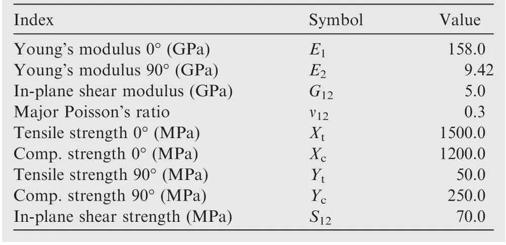
Table 1 Performance parameters of T800/6249 prepreg.
To realize a lightweight design, the layers in different areas of the sandwich box beam should match with its load bearing state, and it is necessary to adopt the discrete design method.As shown in Fig. 2, the beam with a length of l is divided into n segments, and the length of each segment is l1, l2, ...,ln. The width bkand height hkof segment k are determined according to the wing section space, and the area density of the beam segment ρkcan be estimated through the following geometric operation:


Table 2 Performance parameters of PMI foam.

Fig. 2 Discretization of the sandwich box beam.
where t0is the single layer thickness of the carbon fiber prepreg, t0=0.08 mm; ρcis the density of the carbon fiber prepreg, and h0kis the height of the web.
The overall mass of the box beam is expressed as:

The design goal of the sandwich box beam is to minimize mbeamunder the assumption that the constraints are satisfied.
2.4. Constraints
2.4.1. Strength constraints
As shown in Fig. 3, the sandwich box beam is simplified to four sandwich plates, and there are three main types of loads on the beam section in cruise state: bend moment Mx, torque T, and shear force Fs.
The normal stress and shear stress in Fig.3 are superposed,and for each sandwich plate, when one of the two stresses reaches the maximum value, the area is classified as a dangerous area.As shown in Fig.4,there are six dangerous areas on the beam section.The stress state of these areas under overload of-1 g and 3 g shall be calculated and compared with the allowed value.29

where f1, f2and f12are the are the tensile, compressive and shear stresses of the carbon fiber respectively, ffand f12fare the equivalent and shear stresses of the PMI foam respectively,and FoS and FoSfare the safety factors of the carbon fiber and the PMI foam respectively. Based on Ref. [30], FoS and FoSfare considered as 1.5.
2.4.2. Stiffness constraint
Due to the characteristic of large aspect ratio, the wings of solar drones are usually flexible,which may cause several detrimental effects.On the one hand,the large deformation caused by gust load leads to an instantaneous change in the aerodynamic force of the wing, causing the working condition of the aircraft to deviate from the design point. On the other hand, it also causes aeroelastic problems, increasing control difficulty.31Therefore, it is necessary to constrain the stiffness of the beam.In the design stage,the rigidity of the wing can be roughly controlled by limiting the relative displacement of the wingtip.
The relative deformation of the wingtip is defined as:

where wtis the actual deformation of the wingtip, and p is the wingspan.


Fig. 4 Dangerous regions and information on check items.
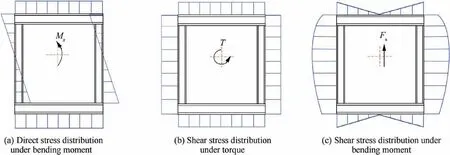
Fig. 3 Stress distribution of sandwich box beam in cruise state.
The stiffness constraint of the sandwich box beam is expressed as:where wlimis the upper limit of relative displacement of tip region in cruising state.
As shown in Fig.5,solar drones exhibit different flight patterns under different wlim, and the value of wlimis not clearly defined in the existing literatures. According to publicly available information,the wlimof most solar powered drones is less than 10% except for some highly flexible drones such as DLR’s verification drone,32whose wlimmay exceed 20%.
2.4.3. Stability constraints
Based on the buckling forms of laminated plates,13it can be predicted that there are three main modes of global buckling failure of sandwich box beam, which are shown in Fig. 6.The buckling form of flanges is compression buckling, and under positive and negative overload, the upper and lower flanges both have the possibility of buckling (Fig. 6(a)). There are two types of buckling failure of webs: one is caused by shear stress(Fig.6(b)),and the other is caused by compressive stress (Fig. 6(c)). In the figure, ‘‘ss” means simply supported.
The load on webs and flanges should not exceed the buckling load.Otherwise,the beam segment will be damaged before strength failure.The stability constraints of box beam segment are expressed as follows:

where Nx,cr, Nxy,cr, and Nxb,crare the buckling loads of different forms respectively, as defined in Fig. 6; Nx, Nxy, and Nxbare the corresponding actual load respectively.
2.4.4. Geometry constraints
The geometrical thickness of the sandwich plate also needs to be limited. If foam with a low density is chosen, the thickness of the sandwich plate may be too large,which causes two problems.One is that the area enclosed by the section center line of sandwich box beam will be smaller and the torsional shear stress will increase, which will weaken the advantages of the thin walled beam. The other one is that it is not conducive to fully utilize the performance of fiber materials in the inner wall of the box beam.
Therefore, the ratio of the thickness of the sandwich plate to the external dimension of the wing beam is limited to 10%, which also makes the structure satisfy the thin plate assumption.33The geometry constraints are expressed as:

where tfrand twrare the relative thicknesses of flanges and webs respectively,tfand tware the actual thicknesses of flanges and webs respectively,and b and h are the width and height of the beam section respectively.
2.4.5. Summary
The optimization model of sandwich box beam for solar drones is expressed as:

where [∙] represents a set of certain parameters at different checkpoints, [f] is the stress at each checking point on the beam,[fmin]and[fmax]are the minimum and maximum acceptable values of stress respectively, [Na]is the actual load on the flanges and webs, [Ncr] is the buckling load, and [tr] is the relative thickness of flanges and webs.
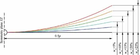
Fig. 5 Solar drones with different rigid wing beams.

Fig. 6 Buckling forms of sandwich box beam.
3. Optimization methodology
3.1. Optimization process
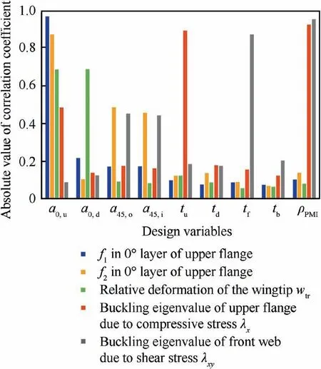
Fig.7 Correlationanalysisbetweendesignvariablesandconstraints.
To avoid huge amount of computation due to parameter coupling, correlation analysis of nine design variables and constraints was conducted.The Pearson correlation coefficient is used to measure the correlation between two variables, and the absolute value of the coefficient is between 0 and 1. The greater the absolute value,the stronger the correlation between variables. Design a reasonable initial laying scheme for the beam, and make each design variable float within±20%.The Latin hypercube method is used to generate 60 sample points,and mechanical calculation along with buckling analysis is carried out. As shown in Fig. 7, a0,u, a0,d, a45,oand a45,iare the main factors affecting the strength and stiffness constraints,which can be designed independently in the first stage.The stability and geometry constraints are mainly influenced by tu, td, tf, tb, and ρPMI, but also secondary affected by other four variables.Therefore,the five variables related to foam are suitable for design in the second stage.
The optimization process is shown in Fig. 8. In the first stage, the four variables related to carbon fiber layers are designed to satisfy the strength and stiffness constraints. This stage of optimization is based on a low-order analytical method, which can perform stress and deflection calculations rapidly.This stage also includes the fluid–structure interaction module to take the aerodynamic changes caused by elastic deformation into account, and [w] is the deflection of each point on the beam. The second design stage is primarily used to determine the five variables related to the foam layers,and the goal of this stage is to satisfy the stability and geometry constraints.This stage is based on the linear buckling analysis method and experimental correction coefficient. Finally,the design results need to be verified by simulation or experiment,and the possible design errors in the first two stages will be further corrected in the process. The design error mainly comes from two aspects: one is the error produced by the low-order and linear calculation process, and the second is the error due to the neglect of foam in the first stage.
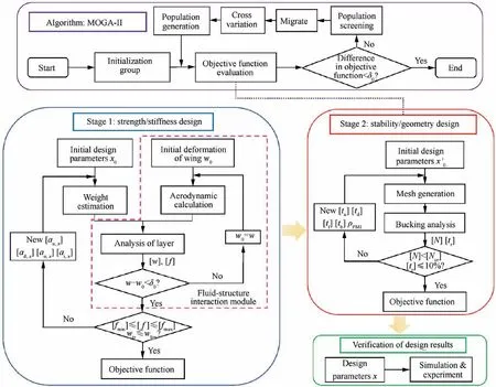
Fig. 8 Optimization process.
Multi Island Genetic Algorithm-Ⅱ(MOGA-Ⅱ)34is used as the optimization algorithm in Stage 2. The multi search elitist method of this algorithm is highly efficient and intelligent,which ensures that the adaptability of the new generation is better than that of the parent generation. In the case of single objective,the Pareto solution set degenerates to a point,forming a special case of multi-objective optimization. MOGA-Ⅱalgorithm is also applicable to the first stage, but with the increase of discretization, the number of iterations greatly increase, so there is no exclusion that there is a better algorithm for this stage.
3.2. Strength and stiffness analysis
3.2.1. Calculation method
In the first stage, the low-order calculation method is used to calculate the stress and deflection of sandwich box beam.The calculation method includes three steps:
(1) Firstly, the box beam is divided into sandwich plates to calculate the stiffness characteristic.
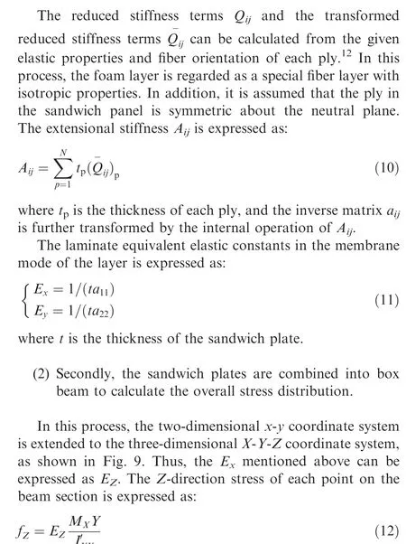
where MXis the moments around the X-axis, which is the bending moment generated by the aerodynamic lift on the wing, and IXX’ is the overall section second moment of area,which is expressed as:
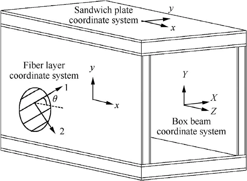
Fig. 9 Coordinate systems of box beam section.
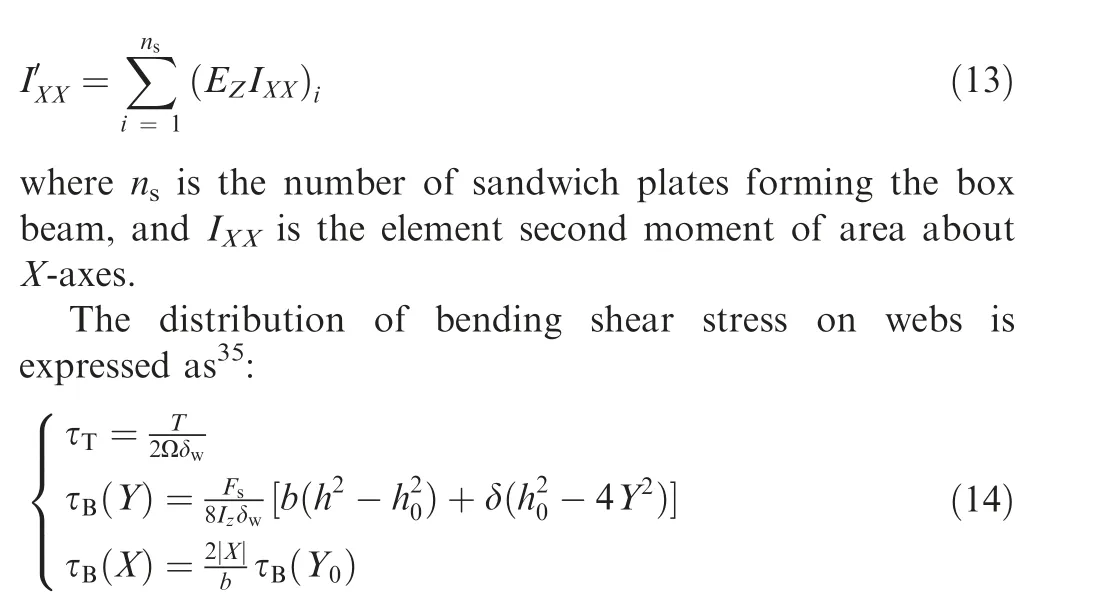
where Ω is the area enclosed by the section center line of sandwich box beam,Izis the inertia moment of the beam section to the neutral axis, δwis the thickness of webs,h0is the height of webs, and Y0is the distance between the web edge to the neutral axis of the section.
(3) Thirdly, the box beam is again divided into plates to study the overall deformation and stress distribution.

where N and M represent force and moment respectively,A is the extensional stiffness matrix, B is the coupling stiffness matrix, D is the bending stiffness matrix, ε0is the strain on the neutral plane of the plate, and K0is the curvature of neutral plane of the plate.
The force matrix N is expressed by Eqs. (12) and (14) as:
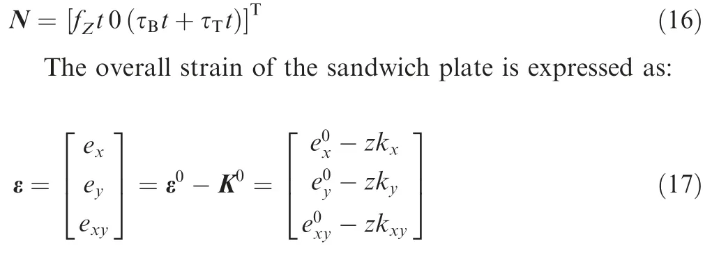
As shown in Fig.9,the angle between axis x and axis 1 is θ.By two-dimensional rotation, the strain in x-y coordinate system is transformed into 1–2 coordinate system which represents the fiber orientation, and the internal stress of the fiber is further obtained.

Fig. 10 Box beam section for verification calculation.
In the calculation of displacement,the equivalent linearization method36is used to analyze the large deformation of the beam. The core of this method is to transform the displacement equation into a linear equation. The approximate solution of displacement is obtained by solving the equivalent moment Me, which has a certain accuracy compared with the numerical solution. The linear equation is expressed as:

where w is the deflection of the section,and the detailed calculation process of equivalent moment Meis given in Ref. [36].
3.2.2. Verification of the method
The accuracy of the above calculation method is verified by FEM. As shown in Fig. 10, the verification model comprises of a sandwich box beam with a length of 2 m, which bears combined load including shear, bending moment and torque,and the distance between the value section and the fixed end l0is taken as 0.4 m.
In finite element analysis, the 8-node continuum shell element with reduced integration (SC8R) is used in the carbon fiber layer, and the 8-node liner brick element with reduced integration(C3D8R)is used in the foam interlayer.Each sandwich plate has 15 nodes in the y direction and the element size in the x direction is about 1.5 times that in the y direction,while the carbon fiber layer and the foam layer respectively have 2 and 4 nodes in the thickness direction. In the calculation, the ‘‘Nlgeom” option is checked, and the results are obtained through multiple iterations. The displacement distribution is shown in Fig. 11.
The calculation results of the two methods are shown in Table 3. Compared to FEM, the maximum error produced by the analytical method is 4.42%,which is small enough compared with the fault tolerance space provided by the safety factor, and the analytical method is applicable to stage 1.
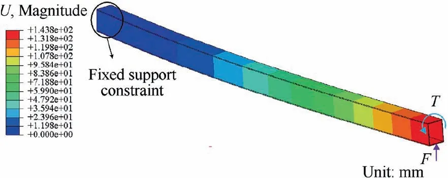
Fig. 11 Direct stress distribution.
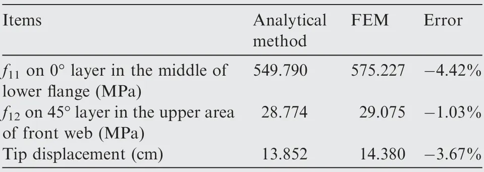
Table 3 Verification of calculation results.
3.3. Stability analysis
3.3.1. Simulation method
Presently, there is no empirical formula for predicting the buckling load of sandwich plates,29and FEM is generally used to predict the buckling load.Although linear buckling analysis cannot consider the nonlinear behavior caused by the defects and large deformation in the structure, it can be used as the first step to evaluate the critical load as it is time-saving and is applicable for low-order optimization design.37
For analyzing the buckling eigenvalue based on linear elasticity, the critical load of structural buckling is expressed as

where KLis the total elastic stiffness matrix of the structure,KGis the total geometric stiffness matrix of the structure,and δ is the feature displacement vector.
As shown in Fig.12,the boundary conditions and external loads are defined on the model.Set the fixed support constraint at one end of the beam,and apply the concentrated load on the loading frame at the other end.By applying two kinds of concentrated forces, the beam section is in different loading state:when FBis applied,the beam is in bending state,while when FTis applied,the spar is in torsion state.The plates are treated as continuum shells in modeling, and the relative thickness, fiber direction, and stacking direction of the elements are specified to simulate the composite. SC8R and C3D8R elements are used in carbon fiber layer and foam layer respectively. Adopt the linear buckling analysis module to carry out analysis on the model, and the buckling eigenvalues are obtained.
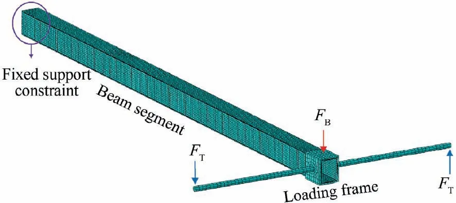
Fig. 12 Finite element model and boundary conditions.
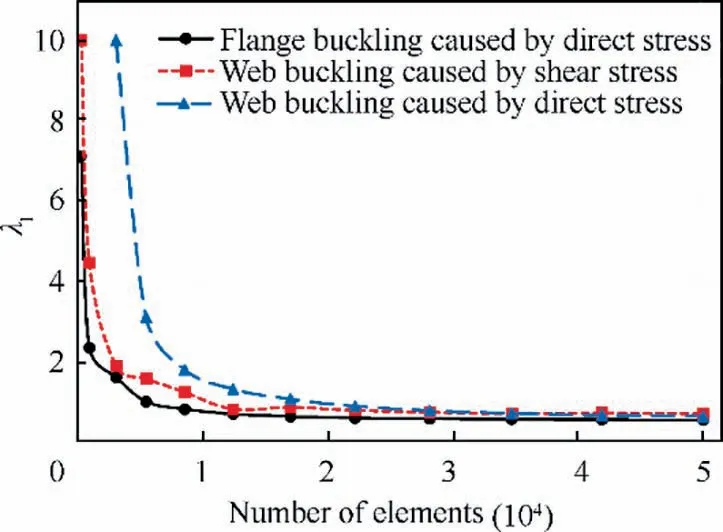
Fig. 13 Mesh convergence analysis.
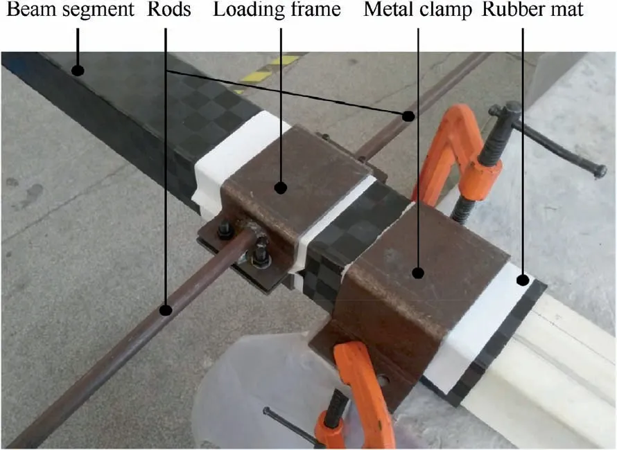
Fig. 14 Experiment tooling and clamping method.
The convergence analysis of finite mesh is conducted. By adjusting the number of nodes around the section, the global mesh number is controlled, and the number of nodes in other directions is consistent with the finite element model in Section 3.2.2. Fig. 13 shows that when the number of nodes increases from 12 to 13, the change amplitude of the three eigenvalues is all less than 3%, which meets the accuracy requirements. Therefore, the number of nodes around the section of each plate is considered as 13.
3.3.2. Verification of the method
The buckling load calculated by linear buckling analysis is verified and corrected by mechanical experiment.Sandwich beam segments with different laying forms are constructed by the same process, and different loads are applied to the beam segments for generating various buckling forms. As shown in Fig.14,the wing beam is fixed with a metal clamp and a loading frame is used for torque loading. Pure torque is generated by applying equal reverse force on the rods protruding from the frame. In addition, the rubber mat is laid between the metal structure and the box beam to disperse stress and avoid local damage.
As shown in Fig. 15, under the same boundary conditions and loads, the damaged structure in the experiment presents the wrinkles with similar position and direction to that in the simulation,which indicates that the results obtained by the linear analysis method have reference significance for the prediction of buckling modes. Besides, in order to ensure that the web buckling occurs before the flange buckling,when carrying out the experiment of Fig. 15 (b), the foam in the web has the characteristics of thin thickness and low density and that in the flange is opposite.
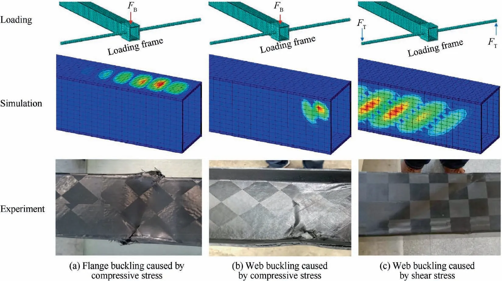
Fig. 15 Three types of buckling failure in simulations and experiments.
Another purpose of simulation and experiment is to determine the correction coefficient cT.The value of cTis related to several factors,such as material system,processing technology,structural deformation, etc. Therefore, it is reasonable to consider that for the same kind of beam, the value of cTobtained from simulation and experiment can be used to predict other points. The relationship between cTand λiis as follows:

where λcris the ratio of the load when buckling occurs in the experiment to the initial external load.
The relationship between [Ncr] and [N] can also be expressed in terms of λcras:

The critical buckling load obtained from the simulation is rounded and applied to the beam incrementally. After each loading,the subsequent operation is carried out until the structure is stable, and the loading step size decreases as the total load approaches the critical load. For damaged beams, it is necessary to check whether the fracture has the following four characteristics: (A) The fiber does not damage in large area;(B)the fiber and foam are not degumming;(C)there is no local collapse or fold on the surface of the structure; (D) the shape of the wrinkles is similar to the simulation results. If all the above characteristics are satisfied,it is considered that the global buckling has occurred, and the load data is recorded.
The comparison between λcrand λ1is shown in Fig.16.By linear fitting of the obtained results, the correlation coefficient is obtained as R2=0.9112, which proves the reliability of the prediction results. The minimum slope of the line between the origin and any point is k=0.7822.Hence,the value of cTcan be considered as 0.78, and the buckling load can be predicted conservatively.
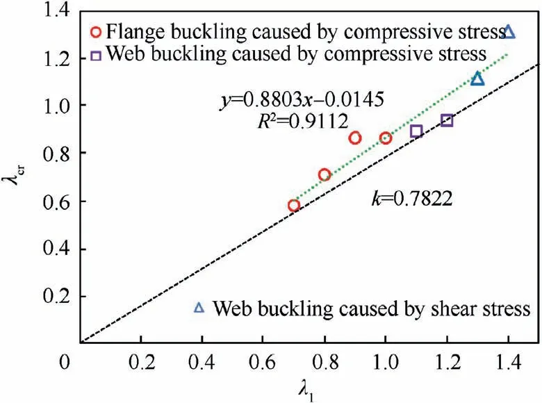
Fig. 16 Comparison of simulated and experimentally obtained buckling eigenvalues.
4. Case study
4.1. Parameters and loading specification
An 18-m wingspan solar drone with conventional configuration is considered as the study object,and the wing beam structure is designed by the process shown in Fig. 8. The objective of the drone is to carry a small photoelectric platform to achieve 14-day continuous cruise in the stratosphere for ground detection.Overall,we found that the continuous cruising capability without energy input is highly sensitive to the structural weight, and if a sandwich box beam is used instead of laminated box beam, the feasibility of the scheme can be greatly improved.
A structural model of the drone is shown in Fig.17,and the main design parameters are shown in Table 4.
The drone is lifted by one middle wing and two outer wings,and the tip root ratio is 1 and 0.4 respectively. With the symmetry plane as the origin, the initial distribution of different loads along the spanwise direction of the wing is shown in Fig. 18.
4.2. Optimization results
As shown in Fig. 19, the middle wing on one side is divided into three segments at an interval of 1.1 m that are indicated by 1–3, and the outer wing is divided into 5 segments with an interval of 1.14 m that are indicated by 4–8.
Fig. 20 shows the design results, where the stiffness constraint is wlim=10%. The number of carbon fiber layers and the thickness of the foam decreases step by step, and the foam density is considered as 50 kg/m3. Due to the limitation of cutting process, the foam with thickness less than 1 mm(dotted line in Fig. 20(b)) is thickened to 1 mm. Further,Fig. 20 shows that the stability constraints of the web can be easily satisfied, and the optimization space of web structure is not large. This is because the torque and shear force of the box beam are smaller than the bending moment.
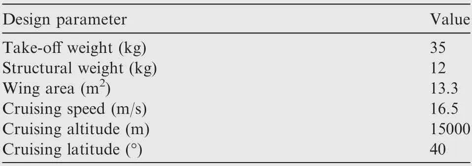
Table 4 Design parameters of the solar drone.

Fig. 17 Digital model of solar drone.
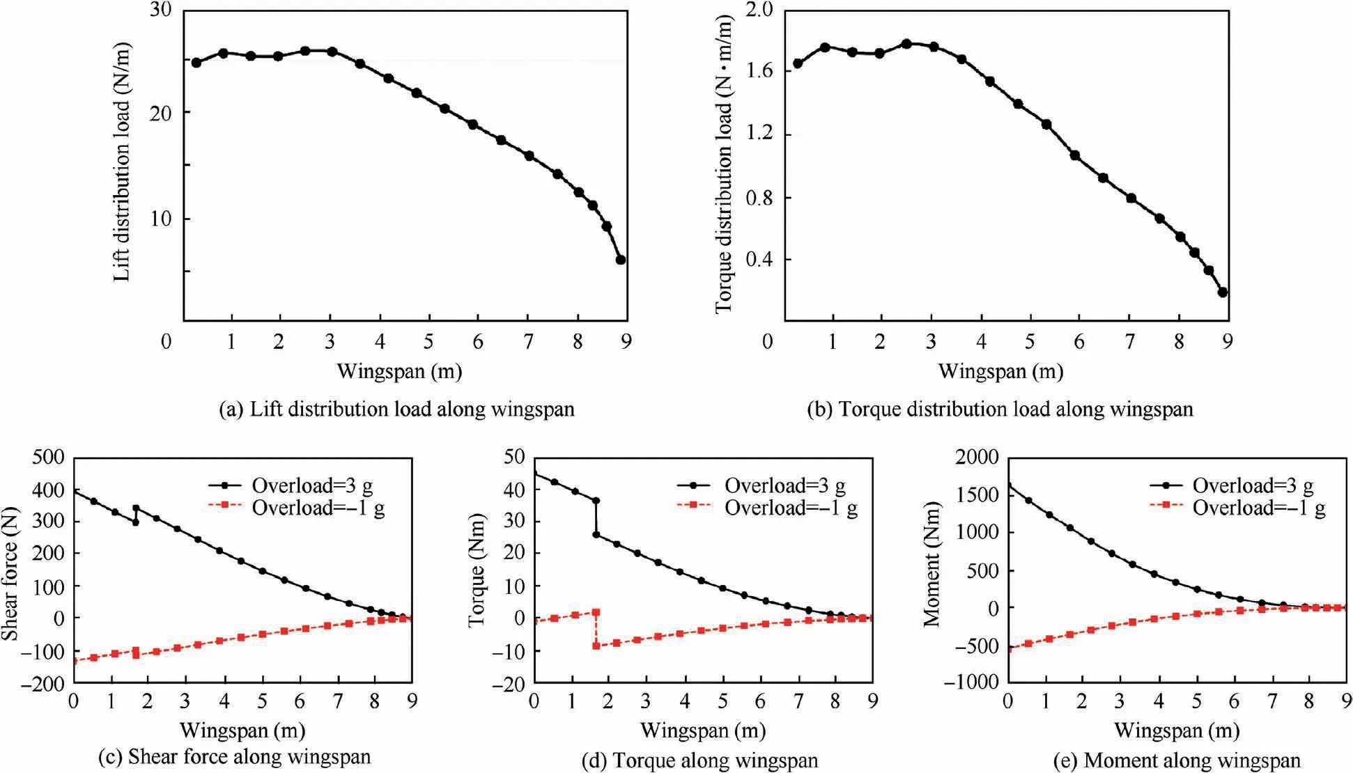
Fig. 18 Load distribution along wingspan.

Fig. 19 Wing segmentation diagram.
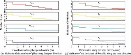
Fig. 20 Variation of design parameters along span direction.
In addition, the design process with wlim=20% was conducted,and the design results of the two groups are compared with the reinforced laminated box beam in Table 5. When wlim=20%,the deflection of the wingtip is 15.04%,indicating that the stiffness constraint does not work in the design process, while when wlim=10%, the deflection of the wingtip is 9.86%, and the weight of the beam is 0.44 kg, which implies that the additional weight cost is required to meet the stiffness constraint. Compared to the reinforced laminated box beam,the sandwich box beam with wlim=10% is 20.4% lighter,which increases the night cruise time by 4.33% and enhances the feasibility of the scheme. In contrast, the laminated box beam adopts more carbon fiber layers to meet stability constraints, resulting in excessive rigidity, and the deflection of wingtip is far less than the constraint value.

Table 5 Comparison of different types of beams.
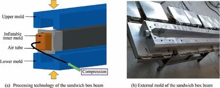
Fig. 21 Forming technology of sandwich box beam.
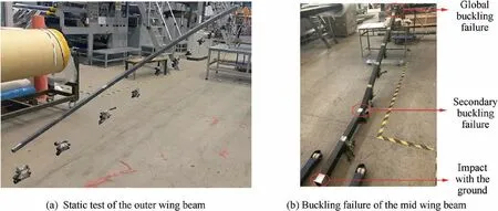
Fig. 22 Loading test of sandwich box beam components.
The process shown in Fig.21(a)is used to manufacture the sandwich box beam.In the curing stage,the box beam is pressurized by inflating the inner rubber mold,while the matching accuracy between the beam and ribs is ensured by the an external steel mold, as shown in Fig. 21(b). Three middle wing beams and six outer wing beams are processed for the drone,and ultimate load tests are conducted, as shown in Fig. 22.It should be noted that the beam in Fig. 22(b) first buckles globally near the root and breaks in an instant. Then, the end of the beam hits the ground, causing secondary buckling failure in the middle region.
The mechanism of buckling failure is studied by post buckling analysis. Taking the #2 segment as the study object, and the analysis is carried out by using the riks method with the node displacement of the first-order linear buckling as the initial imperfection.As shown in Fig.23,S11 represents the normal stress along the fiber orientation, and the existence of the initial imperfection makes the compressive stress concentration region appear at the edge of the upper flange. When the arc length is 0.1, the compressive stress in this region is 2.1 times of the tensile stress of the lower flange, and the middle area of the flange bears only a small part of the compressive stress.With the arc length increasing to 0.3,the ratio increases to 3.4 times,and when the arc length continues to increase,the compressive stress on the flange will be more concentrated in the edge area. Once the compressed fiber breaks, the structural integrity will be destroyed,which will induce the structural collapse in the test.
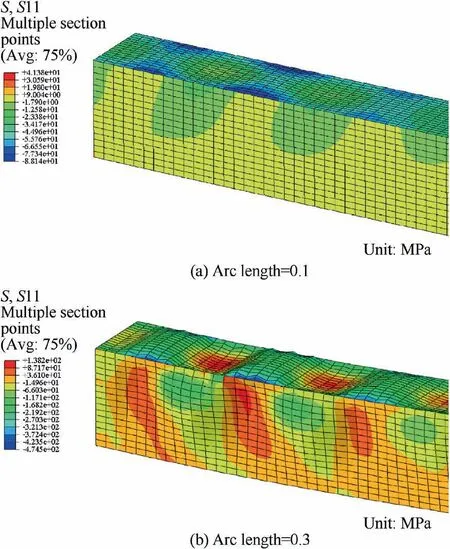
Fig. 23 Post buckling behavior of beam segment.
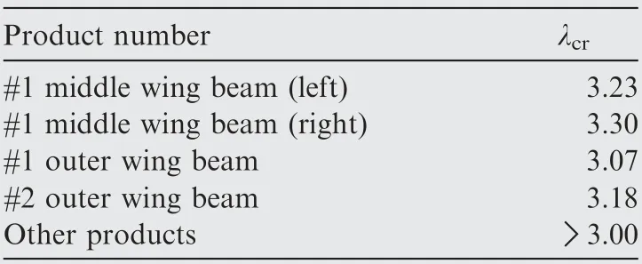
Table 6 Ultimate load test of products.
As shown in Table 6,some products were tested for failure,and the others were tested with maximum overload of 3 g. In the test,buckling failure of all the products occurs in the upper flange, and the test results show that the buckling load of all the beams is higher than the design requirements. These test results further verify the feasibility of the optimization design process and calculation method proposed in Section 3.
5. Analysis
5.1. Analysis scope and standardized model
In the case study,the application of the sandwich box beam in a small-scale solar drone was explored,but the applicability of such beams to solar drones of other scales must be further studied. The scale of a solar drone can be characterized by three main parameters:wingspan,aspect ratio,and wing load.Since the design of solar powered aircraft strictly follows the energy conservation and mass conservation equations, their design parameters usually fall within a certain range, and the parameters of 12 solar drones successfully completed flight were collected. As shown in Fig. 24, the wingspan of these solar drones is between 5 m and 80 m, the aspect ratio is between 12.3 and 31.3,and the ratio of takeoff mass W to wing area S,which is known as the wing load,is between 2.4 kg/m2and 6.3 kg/m2.The characteristics of high aspect ratio and low wing load of solar drones are obvious in the figure. Although the wings of these aircraft are not simply cantilever structures,their dimensions still have reference significance for our study of laws.
In addition, the relative dimensions of beam sections were unified. Fig. 25 shows an FX63-137 airfoil with the chord length of c and the attack angle of a=3°.The beam is placed at 30.9%chord length,and other dimensions of the box beam section are shown in the figure. Once the wingspan and the aspect ratio are determined, the external dimension of the box beam is determined.Combined with the wing load parameters, and using the optimization process in Section 3.1, the sandwich box beam with minimum mass applicable to the drone is obtained.
Based on these design results,this section explores the application of sandwich box beam in solar drones.Among them,the calculation about the stiffness constraint in Section 5.2 is based on the analytical method proposed in Section 3.2,and the analysis about the stability constraints in Section 5.3 is based on the finite element calculation model in Section 3.3. However, due that too many cases are involved in the research,it is impossible to conduct the test on each case,and the correction coefficient of buckling eigenvalue is not fixed.Therefore,in the analysis of buckling behavior,the ideal value λ1based on the FEM is used.
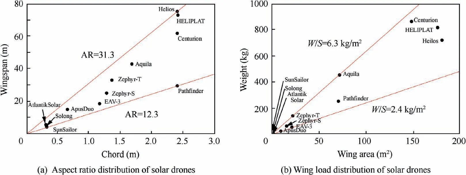
Fig. 24 Statistics of aspect ratio and wing load of solar drones.

Fig. 25 Relative position of box beam section in a wing rib.

Fig. 26 Wing segmentation.
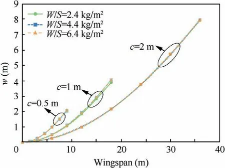
Fig. 27 Variation in deflection of different wing beams.
5.2. Analysis of the stiffness constraint
Here, the effect of stiffness constraint on sandwich box beam of solar drones with different scales is examined. The wings with chord length of 0.5, 1, and 2 m are selected as the study objects, and the wing loads are considered as 2.4, 4.4, and 6.4 kg/m2. As shown in Fig. 26, the wings on one side of the fuselage are divided into six segments for discrete design.
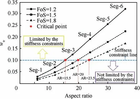
Fig. 28 Validity of stiffness constraint.
Considering the strength constraints only, the deflection curves of wing beams with a high aspect ratio of 36 under different chord lengths and wing loads are shown in Fig.27.It is obvious that the deflection curves of wing beams are independent of the wing load. In addition, among the three groups of curves in the figure,only the coefficient of the quadratic term is different,which implies that the ratio of deflection to spanwise position of the wing is not related to the chord length.It can be concluded that when the strength constraints are only satisfied,the deflection curve of the wing is just related to the aspect ratio and safety factors.
Taking chord length as 1 m and the wing load as 4.4 kg/m2,a wing with aspect ratio between 6 and 36 is now studied.Fig. 28 shows the variation in the relative deflection of the wingtip with different aspect ratios and safety factors when only the strength constraints are satisfied. The curves in this figure are divided into two parts by the stiffness constraint line(wlim=0.1). In the case of FoS=1.5, the aspect ratio of 20 represents the critical point to determine whether the stiffness constraint can affect the design. If the aspect ratio is less than 20, the beam segment designed according to the strength constraints can directly meet the stiffness constraint, but if the aspect ratio is greater than 20, the beam segments satisfying strength constraints need to be further optimized to meet the stiffness constraint. When the safety factor decreases or increases, the critical point moves to the left or right, and the restriction effect of the stiffness constraint on beams with different aspect ratios also changes.In addition,the rise or fall of the stiffness constraint line also moves the critical point. If the stiffness constraint rises, the critical point moves to the right, and the areas that are not affected by the stiffness constraint increase.
Overall, Fig. 28 indicates the necessity of stiffness design.Fig. 29 shows two solar drones with same wingspan and wing load but different aspect ratio.When only strength constraints are considered in the design, the deflection of the drone with AR=15 is less than 10%, while that of the drone with AR=25 is higher than 10%. This indicates that the stiffness constraint can be ignored in the design process of the former case, but it must be considered in the latter case. The simulation results are consistent with Fig. 28.
5.3. Analysis of stability constraints
Here, the effect of stability constraints on sandwich box beam for solar drones is explored.Further,the applicability of sandwich box beam to solar drones of different scales is analyzed,and the rules of mass increment caused by stability constraints are investigated.Based on the case study,only the buckling of the upper flange is considered under the condition that the webs do not buckle.
The nine wings shown in Fig. 27 are considered as study objects. Firstly, the stiffness constraint line is set to wlim=0.25, and the buckling eigenvalues of wing segments are shown in Fig.30.It is evident that the buckling eigenvalue curves are basically independent of the chord length, and the curves under the same wing load have a high degree of coincidence.The larger the wing load,the larger the buckling eigenvalue of the segment in the same position, and the buckling eigenvalue shows a quadratic rising trend near the root of the wing. However, even when the wing load is maximum and the wing segment is closest to the root, the eigenvalue is still about 0.5. This means that when the stiffness constraint line is at a high level, the wing beam segments of solar drones of all scales are limited by stability constraints,and in this case,sandwich box beam is applicable to general-scale solar drones.

Fig. 29 Deformation of solar drones.
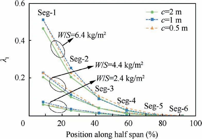
Fig. 30 Buckling eigenvalues when only strength and stiffness constraints are satisfied (wlim=0.25).
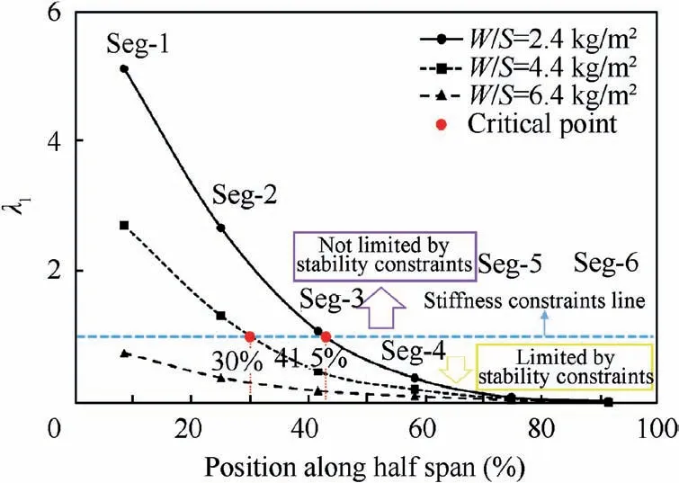
Fig. 31 Validity of stability (wlim=0.1).
Secondly, a wing with c=1 m is considered, and the stiffness constraint is set to wlim=0.1.The buckling eigenvalues of wing segments under different wing loads are shown in Fig.31.It can be seen that when the wing load is in the middle or extreme position, the beam section near the root is no longer limited by stability constraints, which means that the box beam designed by stiffness and strength constraints can directly satisfy the stability constraints, and it is not necessary to adopt sandwich box beam. However, the wing segments near the tip are still affected by stability constraints, and it is necessary to use sandwich structure to improve the structural stability.
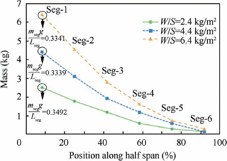
Fig. 32 Mass distribution of beam segments (wtr=0.25).
Now,a wing with c=1 m is analyzed to explore the impact of stability constraints on mass increment, and the stiffness constraint line is set to wlim=0.25. As shown in Fig. 32, as the position of the wing segment approaches the wing root,the mass of the segments msegtends to rise parabolically. Further, the higher the wing load, the larger the mass increment.The ratio of the structural weight to total weight of solar drones is usually about 1/3,1which means that when the ratio of the wing segment weight to the aerodynamic lift provided by this segment Lsegis higher than 1/3, which is not conducive to reduce the structure weight. For the ‘‘Seg-1” under three different wing loads in Fig. 32, the structural weight is close to 1/3 of the aerodynamic lift in cruising state. Thus, it can be inferred that when the aspect ratio is higher than 36,the feasibility of solar drones is reduced due to the excessive weight of the beam.
In the second stage of design, stability constraints cause extra weight to the box beam, as shown in Fig. 33. For laminated box beam, the mass increment is sensitive to the wing load and the position. As the segment approaches the wingtip or the wing load decreases, the mass increment increases. On the contrary, for sandwich box beam, the mass increment is not sensitive to the wing load or the position, and the mass increment is relatively stable, fluctuating between 20% and 30%. By contrast, it can be found that sandwich box beam is more beneficial to structural weight reduction than laminated box beam. The smaller the wing load or the closer the segment is to the wingtip, the more beneficial is the sandwich box beam. In Fig. 33, when the wing load is 6.4 kg/m2and the beam segment is farthest from the wing tip,the mass increment of laminated box beam is smaller than that of sandwich box beam. In this case, laminated box beam is better than sandwich box beam.
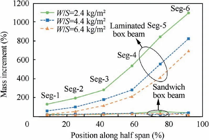
Fig.33 Mass increment due to stability constraints(wtr=0.25).
5.4. Sensitivity analysis of buckling eigenvalue
The variation in layer thickness or foam density can change the buckling eigenvalue. When these parameters change, it is usually necessary to conduct the buckling analysis by FEM. Sensitivity analysis of buckling eigenvalues can serve as a quantitative way to improve the stability and can provide useful reference for engineering applications.
Considering the wingspan, aspect ratio, and wing load at high and low levels, the sandwich box beam is designed for these six wings with the method shown in Fig.8.Accordingly,the thickness of different layers is increases or decreased, and the variation in buckling eigenvalue is obtained, as shown in Fig. 34. The thickness of foam in the flange and the thickness of the 0°ply strongly affects the buckling eigenvalue,while the thickness of the±45° ply has a negligible effect. By contrast,the thickness of the foam in the web hardly affects the buckling load.When the aspect ratio increases to 32,the influence of the 0°ply thickness is stronger than that of the flange foam thickness, and when the wingspan is increased to 80 m, the thicknesses of the two materials have similar impact.
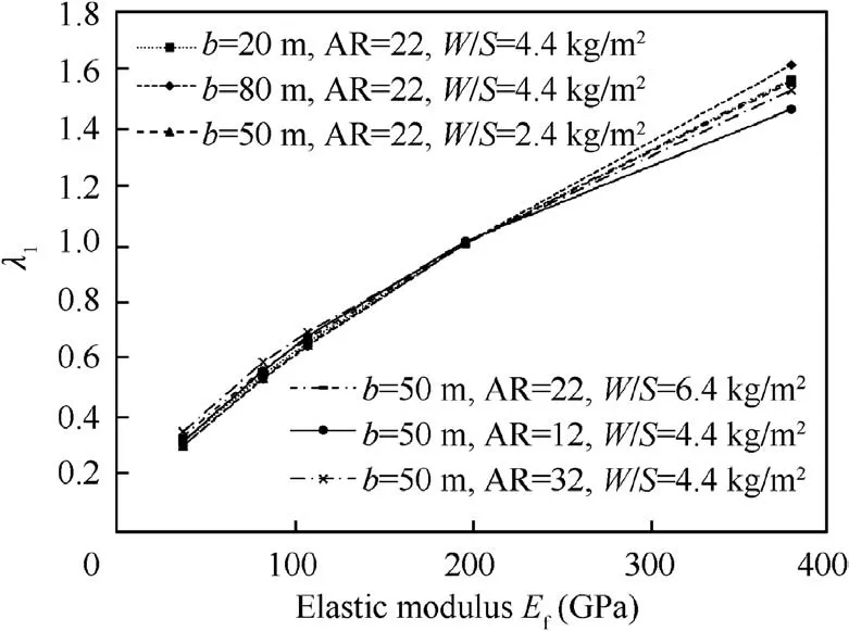
Fig. 35 Effect of PMI foam density on buckling coefficient.
Foams with different densities have a wide range of performance indicators. Therefore, the structural stability can be improved by changing the foam density under the satisfaction of geometric constraints. As shown in Fig. 35, the buckling characteristic value is positively correlated with the elastic modulus of the foam, and the six curves are highly consistent,indicating that the effect of foam density on the buckling characteristics is not related to the scale of solar drones.
To quantitatively compare the effect of various factors in improving the buckling characteristics,the stability profit coefficient pcis defined as
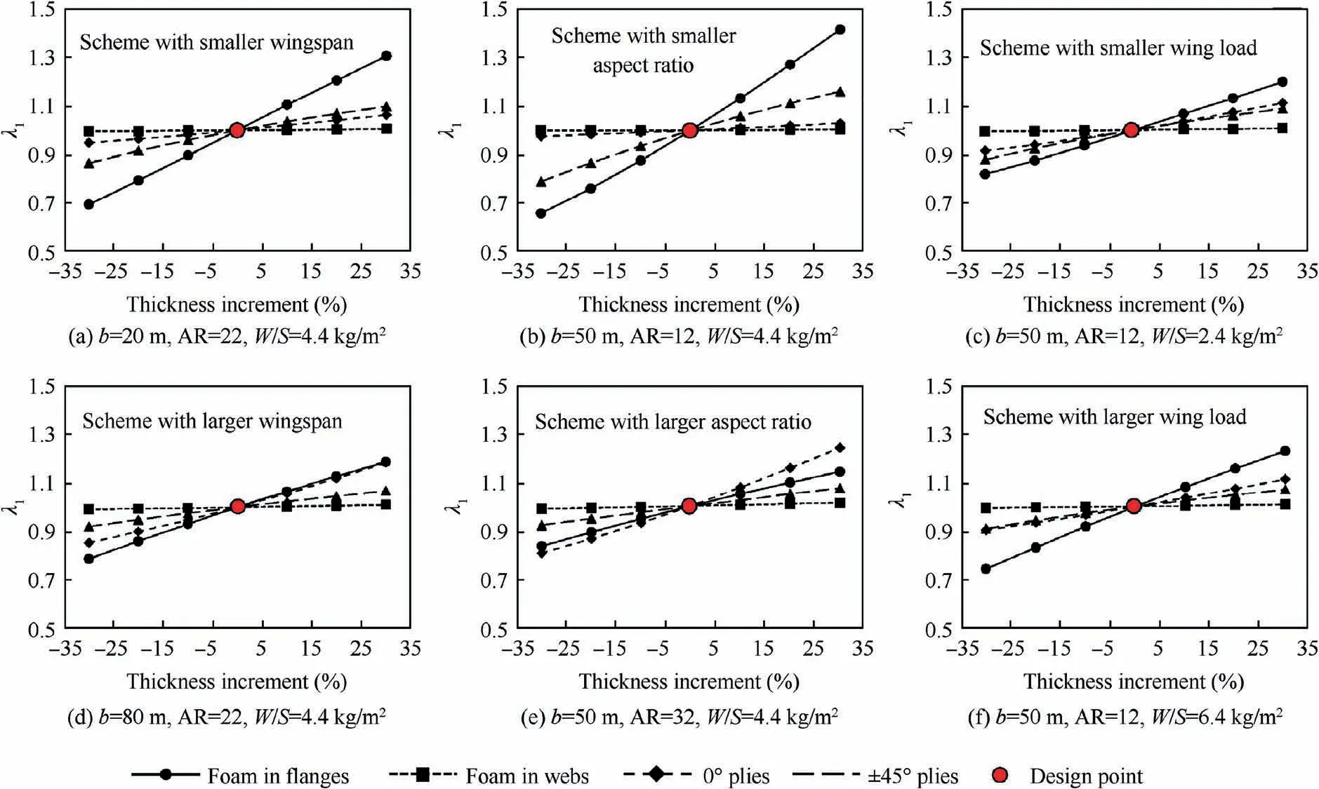
Fig. 34 Influence of variation in ply thickness on buckling load of wings with different configurations.
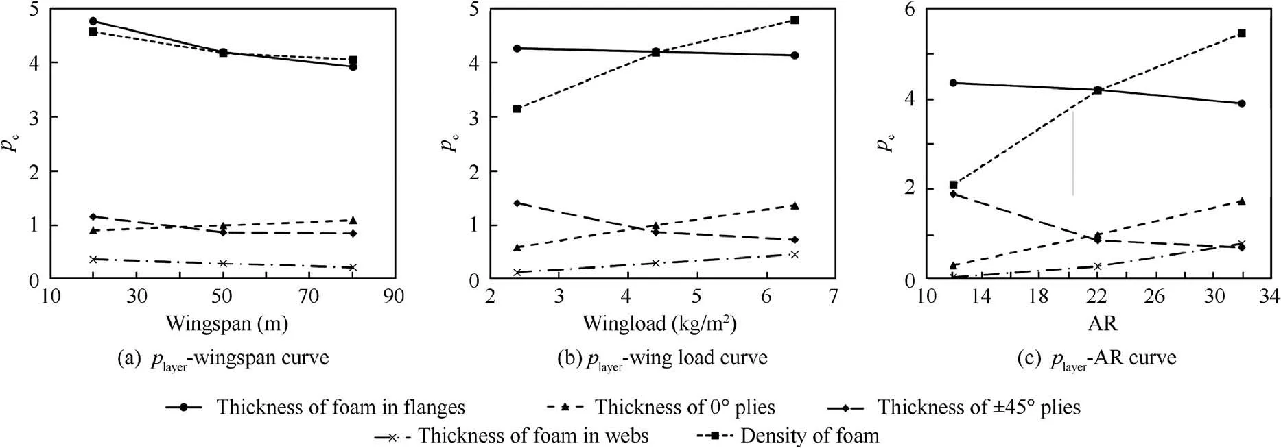
Fig. 36 Variation in player caused by the change in wing configuration.

where Δλ1is the increment of the buckling eigenvalue, Δρsis the increment of section density after stability improvement,and ρsis the section density before stability improvement.
As shown in Fig. 36, as the wingspan, aspect ratio, and wing load increase, the thickness of foam in flanges and that of 45° plies cause smaller pcvalues, while the thickness of 0°plies facilitates larger pcvalues. The other two factors show different trends in different graphs.As the wingspan increases,the foam density and the thickness of foam in webs cause smaller pcvalues,while the pcvalue of the two factors becomes larger with the increase in wing load and aspect ratio. By comparison, it is found that the profit coefficient of flange foam thickness and foam density is generally higher than that of the other three factors, indicating that these two factors should be initially considered in stability improvement.
Fig. 36 also shows that for solar drones of different scales,the optimal way to improve the buckling eigenvalue is not the same. When the wing load or the aspect ratio is small, the thickening of the foam in flanges facilitates higher profit coefficient,and it is the best way to improve the stability characteristics. When the wing load or the aspect ratio is large,increasing the foam density enables higher profit coefficient,and it is the preferred method to improve the stability characteristics.When the wing load or the aspect ratio is in the medium range, the profit coefficient of the two design parameters are equal, which means either way can be chosen.
6. Conclusions
(1) The error of low-order calculation method is less than 4.5%, and it is applicable to the design of sandwich box beams.Combined with experimental correction factors, the linear FEM can be used to estimate the buckling loads of the sandwich box beam.
(2) Compared to the laminated box beam,the sandwich box beam based on the proposed two-stage optimization design method can reduce the weight by 20.4% and can extend the night cruise time of the solar drone by 4.33%.
(3) The effect of the stiffness constraint on wing beams is only related to the safety factor and aspect ratio, and the effect of stability constraints on wing beam is only related to the aspect ratio and wing load.
(4) When aspect ratio and wing load are both high and the stiffness constraint is low, sandwich box beam is not suitable in the regions near the wing root.
(5) Compared to the laminated box beam, sandwich box beam requires less weight for stability constraints, and the mass increment of the foam is not related to the scale of solar drones, and it always ranges between 20% and 30%.
(6) The two best way to improve the buckling eigenvalue of sandwich box beams is to increase the thickness of the upper flange or to increase the foam density. When the aspect ratio or the wing load is small, increasing the thickness of the upper flange thickness is more beneficial. Otherwise, increasing the foam density is better.
Declaration of Competing Interest
The authors declare that they have no known competing financial interests or personal relationships that could have appeared to influence the work reported in this paper.
 CHINESE JOURNAL OF AERONAUTICS2021年10期
- CHINESE JOURNAL OF AERONAUTICS的其它文章
- Direct dynamic-simulation approach to trajectory optimization
- A strong robustness open-circuit fault diagnosis strategy for novel fault-tolerant electric drive system based on d-q-axis current signal
- Nonlinear vibration response characteristics of a dual-rotor-bearing system with squeeze film damper
- Ground maneuver for front-wheel drive aircraft via deep reinforcement learning
- Numerical simulation of a UAV impacting engine fan blades
- Recent advances in precision measurement &pointing control of spacecraft
