Enhanced electromagnetic-interference shielding effectiveness and mechanical strength of Co-Ni coated aramid-carbon blended fabric
Qin WANG, Yumeng XU, Siyi BI, Yinxiang LU
Department of Materials Science, Fudan University, Shanghai 200433, China
KEYWORDS Aramid fibers;Carbon fibers;Cobalt-nickel (Co-Ni) Coating;Electroless plating;Electromagnetic shielding
Abstract An efficient method was proposed to prepare high-performance conductive Aramid-Carbon Blend Fabrics (ACBF) with cobalt–nickel (Co-Ni) alloy coatings, which is conducive to industrial production. The grid-like substrate composed of aramid and carbon fibers was innovatively used in flexible Electromagnetic Interference(EMI)shielding materials.The natural network structure is advantageous to the uniform deposition of metal particles to the establishment of conductive pathways subsequently in order to improve conductivity.The induction of a synergistic effect from Electromagnetic (EM) wave-reflection and EM wave-absorption through the whole carbon-Co-Ni-ternary system notably enhanced the EMI Shielding Effectiveness (SE) value to an average of 42.57 dB in the range of 30–6000 MHz.On the other hand,together with the inherent toughness of the alloy coatings,the tensile strength of the aramid fibers used for bulletproof made a significant contribution to the desired mechanical properties.The light weight of the resultant composite made it applicable to aerospace vehicles simultaneously. X-ray Photoelectron Spectroscopy (XPS) was conducted to investigate the variations of elements and groups on the sample surface in pretreating process.The elemental components and surface morphologies of fabric samples during different stages of the process were investigated by Scanning Electron Microscope(SEM)and Energy Dispersive spectrometer(EDX)measurements.X-Ray Diffraction(XRD)results indicated that the obtained Co-Ni alloy coating had a combined Hexagonal Closed-Packed (HCP) and Faced-Centered Cubic (FCC) crystalline phase. The relatively high corrosion resistance demonstrated in different acid and alkaline conditions was instrumental in more complex environments as well.
1. Introduction
With the prosperous evolution of aerospace age,overwhelming electronic devices (such as high-power radars, inertial navigation system, communication station and onboard computer)have been an indispensable part of aircraft with various functions. This electronic equipment managed over wireless networks will generate undesired Electromagnetic(EM)radiation, which would not only destroy the normal operation of neighboring electronic equipment or operation systems, but also disorder biological environment of the pilots.1–5Materials with high Electromagnetic Interference (EMI) shielding performance are required for non-planar parts like the skin,hatch cover and other electronic devices. Under such circumstances,exploiting flexible EMI shielding materials with high EMI Shielding Effectiveness (SE) is in high demand to get rid of aero EMI problems. Nowadays, most researchers use cellulose-based fabrics (like cotton,6ramie7and etc.) or commonly synthetic polymer fabrics (like polyester,8nylon9and etc.)as supporting substrates for their cost-effectiveness.However, in the specific applications like military and space aircraft, the mechanical strength of EMI shielding materials should also be taken into consideration.With outstanding performances of high tensile strength (single filament strength reaches 3850 MPa),low density of 1.44 g/cm3,good toughness(6 times higher than graphite fiber) and long service life, aramid fiber has been utilized as a popular supporting material in aviation, hard body armor, engine nacelles, maritime vessels, etc. On the other hand, high chemical stability of aramid fibers leads to poor reactivity on inert surface with surrounding materials by neither chemically reacting nor physically interlocking.10–14Furthermore, unlike carbon fibers, the electrically insulating nature of aramid fibers limits the selfdesign of multifunctional composites with sensing, joule heating and detection functions.While carbon fibers with satisfying electrical conductivity could be promising for a wide application in the military industry and aerospace field,15–17an obvious disadvantage of the carbon fibers is its fragileness. Dogan et al.18researched the EMI shielding performance and mechanical properties of carbon fibers,aramid fibers and their twilled composite fibers, and compared the applicability in radiation-proof baby car seats.However,relatively low SE values may be unsatisfactory in the aviation field, and the composite plates are not suitable for non-planar electronic equipment in aircraft as well. To tackle this problem, we thought of blending aramid and carbon fibers into a fabric as an improved structural substrate so that the properties of the two were complementary, and firstly further functionalize the fabric surface with efficient strategy to optimize its EMI shielding performance and mechanical strength simultaneously.
A large number of studies have adopted surface functionalization to enhance fiber performance.Zhang et al.19fabricated silica sol-coated glass fibers by impregnation. On this basis,Tang et al.20,21subsequently combined hot compression or heat treatment to obtain reinforced fiber-based layered composite materials.Better EMI SE value can be achieved by minimizing the radiation passing through the shielding materials by absorption, reflection or multiple dissipation of EM radiation inside the material.22On the basis of attenuation principles, EMI shielding materials are divided into two categories:wave-absorption dominant materials and wave-reflection dominant materials. Magnetic materials (like iron, cobalt and nickel)23,24and carbon-based materials (involving carbon black, carbon fibers, graphite, graphene and carbon nanotubes)25–28are wave-absorption dominant materials and metals are classified as typical wave-reflection dominant materials.Metallic textiles have been a promising focus of recent research on flexible EMI shielding materials,which combine the advantages of metals and textiles such as high conductivity, light weight and pliability.29–31A plethora of studies have been carried out to obtain textiles covered or filled by metals for EMI application.Ozen et al.32utilized silver-coated Polyamide(PA)fibers with fineness of 1.7 dtex to fabricate a needle-punched nonwoven fabric by electroless plating, whose maximum SE value of 36.53 dB was observed in the frequency range of 15–3000 MHz. Merizgui et al.33prepared Multi-Walled Carbon NanoTubes (MWCNTs) and Fe2O3particles on kenaf fibers in hand layup method,which showed improved mechanical properties and the SE reached 14.5 dB at best in J band microwave frequency. The combination of carbon fibers and metallic coating is supposed to attenuate the electromagnetic waves by absorption and reflection loss mechanism, resulting in an enhanced EMI SE value. In addition, electroplating,34vacuum deposition35and airbrushing36are also commonly used to construct metallic coat on fibers. In the above methods, the electroless plating does not require an external power supply or auxiliary electrode, which significantly reduces energy consumption, instead, it relies on the self-catalytic active centers on the surface of the substrate to plate, which makes the porosity of the coating lower and the thickness more uniform. There is no edge effect in electroless plating so that post-processing is not demanded generally. Since the electroless plating has no special requirements on the shape of the workpiece to be plated, it is extremely appropriate for plating on Aramid-Carbon Blend Fabrics (ACBF) with low surface friction.
In our present work, cobalt-nickel (Co-Ni) alloy (as functional layer) coated ACBF (as supporting substrate)was firstly attempted to be prepared by efficient electroless plating method. ACBF was modified by 3-Aminopropyltrimethoxysilane (APTMS), a type of trifunctional alkoxy silanes acting as a molecular bridge between organic(ACBF)and inorganic(Co-Ni alloy coating)37–39substance.To be specific,Co and Ni Nanoparticles(NPs)catalyst moieties were loaded on the modified surface of ACBF and functioned as anchor sites for Co-Ni alloy deposition. The activated ACBF was immersed in electroless solution for external Co-Ni alloy in-situ growth. Elemental compositions, surface morphologies and crystalline identities were analyzed by Energy Dispersive spectrometer (EDX), Scanning Electron Microscope (SEM) and X-Ray Diffraction (XRD), respectively. The enhanced EMI SE performance, corrosion resistance and mechanical strength of Co-Ni alloy coated ACBF was also investigated. The ultimately obtained Co-Ni alloy coated ACBF endows great potential in wearable electronic applications and is favorable to industrial production owning to easy-operated plating process.
2. Experimental
2.1. Materials
The initiate aramid fibers and carbon fibers were purchased from Taicang Biqi Novel Material Co. Ltd. After the blend fibers were woven into a plain weave by a single-cylinder handloom, the fabric was cut into a 10 cm×15 cm patch previously, whose weight was 290.89 g (1.94 g/cm2). Moreover,aramid fibers and carbon fibers were woven into a plain weave and cut into the same size as the control groups respectively.3-APTMS was acquired from Shanghai Chemical Regent Co.The Deionized (DI) water was purified by a Milli-Q system(Milford, MA, USA). All other reagents were of analytical grade purity and used without further purification unless otherwise mentioned.
2.2. Fabrication overview
The fabrication of conductive Co-Ni coated ACBFs consisted of three consecutive procedures, namely, minor modificationwith APTMS, two-step activation with Co and Ni NPs, and Co-Ni alloy coating deposition. ACBF samples were precleaned by DI water repeatedly to remove impurities and dust from the weaving process and dried at 60°C for 3 min. Afterward,the clean fabric samples were soaked in the acetone solution of 0.125wt%APTMS for 10 min and heated in an oven at 80°C for another 5 min. The purpose of uniform selfassembled APTMS coating was to facilitate the adhesion between Co-Ni coatings and ACBF substrates through-NH2groups bonding originated from APTMS. Activation seeding was conducted by dipping the modified ACBF samples(abbreviated as ACBF/APTMS) into Co2+and Ni2+aqueous solution at room temperature (rt) with continuously magnetic stirring for 30 min to chelate Co2+and Ni2+cations. After being rinsed by DI water for seconds, Co2+and Ni2+absorbed samples (abbreviated as ACBF/APTMS/Co2+/Ni2+)were in-situ reduced by 0.25 mol/L sodium borohydride(NaBH4)solution at rtfor 15 min.Prior to the electroless plating stage,the samples activated by Co0and Ni0(abbreviated as ACBF/APTMS/Co0/Ni0) were thoroughly washed by DI water and dried at 80°C again to prevent the subsequent plating bath solution from contamination. Co-Ni alloy coating deposition was achieved by immersing ACBF/APTMS/Co0/Ni0samples into the electroless plating bath solution as shown in Table 1. Sodium hypophosphite (NaH2PO2∙2H2O), KNatartrate(C4H4O6KNa∙4H2O)and ammonium sulfate((NH4)2-SO4)were served as reductant,complexing agent and stabilizer for the solution, respectively. The pH was adjusted to 9.4 in virtue of ammonium hydroxide solution and the temperature of the plating bath solution was kept at 80°C in a preheated water bath. After 30 min electroless deposition, the resultant Co-Ni alloy coated ACBF labeled as ACBF/Co-Ni were rinsed by DI water and dried at constant 80°C to remove redundant plating bath.The quality of the obtained sample was 369.93 g,and the metal content was 79.04 g in total (0.53 g/cm2). The amount of aramid and carbon fibers, ACBF and coated ACBF/Co-Ni were specified in Table 2. Control samples (i.e.aramid fabric and carbon fabric coated with Co-Ni alloy,abbreviated as aramid/Co-Ni and carbon/Co-Ni) were treated in the same method. The complete workflow of the ACBF/Co-Ni was illustrated in Fig. 1.
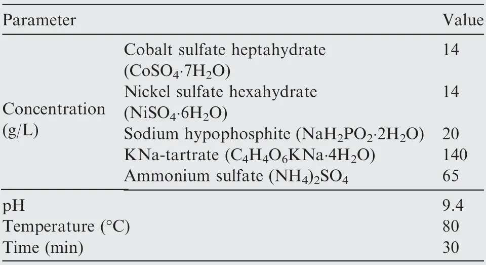
Table 1 Composition and operation conditions of Co-Ni electroless plating bath solution.
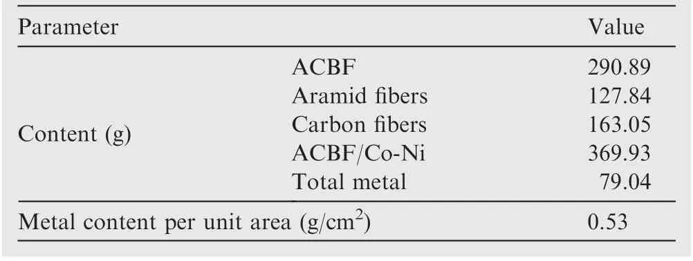
Table 2 Quality comparison of ACBF (10 cm×15 cm)before and after electroless plating.
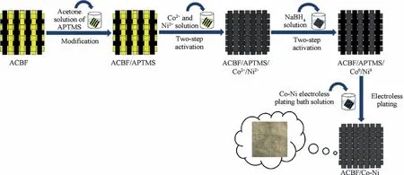
Fig. 1 Schematic illustration of fabrication of Co-Ni coated ACBF plate (dimension was not drawn in scale).
2.3. Characterization
All ACBF/Co-Ni samples were conditioned for 24 h according to ASTM D1776-04 ((20±2) °C and (65±2)% relative humidity) before characterization. X-ray Photoelectron Spectroscopy (XPS) was performed on Kratos multifunctional X-ray photoelectron spectroscope (AXIS ULTRA) with Mg Kα source radiation at 14.0 kV and 25 mA. Peak fitting was carried out according to Shirley-type background subtraction by curve fitting XPSPEAK 4.1 software with Gaussian-Lorentzian 40%.The surface morphology and element composition of the Co-Ni alloy coatings were investigated by a Field Emission-Scanning Electron Microscope(FE-SEM,S-4300SE,Hitachi, Japan) coupled with an energy-dispersive X-ray. The SEM graphs were in the form of secondary electron images.The surface of the observed sample was sputtered with a platinum layer before measurement. X-ray fluorescence spectrometry attached with EDX was carried out on an RBD upgraded PHI 5000C ESCA system (Perkin Elmer) equipped with Mg Kα source (1253.6 eV photons). The high voltage and the current were kept at 14.0 keV and 25 mA respectively, and the detection angle was set at 54°. XRD (Rigaku Dymax, Japan)patterns were documented at rtwith a 2θ region from 10° to 70° using Cu Kα radiation from a 40 kV X-ray source. The conductivities(ρ)and the square resistances(Rs)of fabric samples were evaluated by a digital 4-point probe ST2258C (Suzhou China) and each sample was measured at least five times to obtain an average value.CHI660e electrochemical workstation(Shanghai China)was utilized to study the corrosion resistance of the coatings in 3.5wt% NaCl solution, 10.0wt%NaOH solution and 10.0wt% HCl solution at rt. The EMI SE measurements were performed by utilizing a spectrum analyzer (ATTEN AT5011, China) at a frequency range of 30–6000 MHz with the method of the coaxial transmission line described in ASTM D 4935–99. The tensile tests were carried out by ZQ-990LB digital tension tester (Dongguan Zhiqu Precision Instrument Co., Ltd.) and the fabric samples were cut into 2 cm×12 cm patches before testing. 1 N force was firstly pre-loaded to straighten the samples, and the gauge length between the upper and lower clamps was 11 cm.
3. Results and discussion
XPS were implemented to analyze the chemical state of samples during the modification and activation processes. Fig. 2(a) documented the spectra of pristine ACBF substrates and modified ACBF/APTMS. In a wide-angle spectrum, signals representing C1s, N1s and O1s were observed at Binding Energy (BE) of 285.08 eV, 399.36 eV and 532.04 eV, respectively, which could be ascribed to the dominant species of ACBF substrates. After modification, the characteristic peak height of C decreased by 24.4%, while that of O increased by 40.6%. However, the peak intensity of N and Si (at BE of 102.08 eV and 153.12 eV in the narrow-angle spectrum for clarity) significantly increased (337.6% and 189.4% respectively).It could be determined that the APTMS molecules were grafted to the surface of ACBF but had no damages to the original elemental composition and chemical state of ACBF substrates. High resolution N1s XPS spectra in Fig. 2(b1)-(b3)further proved the variation.Compared with the primitive ACBF sample (Fig. 2(b1)), the ratio of (-NH2)/(=NH) of modified ACBF/APTMS (Fig. 2(b2)) obviously increased owing to the attachment of-NH2from APTMS molecules.The-NH2peak moved to a higher BE (from 399.28 eV to 401.13 eV) after absorbing Co2+and Ni2+in Fig. 2(b3). This shift certificated that Co2+and Ni2+had chelated with-NH2, for the chelation of the metallic ions reduced the electron cloud density of the N atom. Fig. 2(c) showed the spectra after Co2+/Ni2+absorption and in-situ reduction.It involved Co2p3 (778.20 eV), Co2p1 (792.18 eV), Ni2p3(852.88 eV) and Ni2p1 (868.24 eV) after exposure to NaBH4solution, which verified the activation sites of Co0and Ni0were obtained on the surface.
The variations of surface elements in each preparation stage were characterized by EDX analysis and the results were shown in Fig. 3(a)-(d). Quantitative data were obtained by matrix ZAF (atomic number correction factor Z, X-ray absorption correction factor A,and X-ray fluorescence correction factor F) correction method. The energy spectrum of the ACBF substrates (Fig. 3(a)) mainly showed the characteristic peaks of C, O and N elements, respectively corresponding to carbon fibers and the phthaloyl phenylenediamine in aramid fibers from fabric substrate. As displayed in Fig. 3(b), the atomic contents of N and O elements in modified fabric were significantly increased compared with pristine ACBF, which is due to the higher N and O contents in APTMS molecules(C6H17NO3Si).The increased O and N elements validated that amino groups (-NH2) from APTMS molecules were successfully grafted onto the surface of ACBF substrates. The presence of Co and Ni elements was observed in activated fabrics as disclosed in Fig. 3(c). The Co and Ni ions were adsorbed on the ACBF surface through chemical coupling with amino groups and reduced to Co NPs and Ni NPs.Multi-metallic catalyst sites were distributed uniformly and served as seeds for the subsequent electroless deposition. The so-called Co-Ni alloy coating was deposited on the ACBF substrate through in-situ growth on Co NPs and Ni NPs activated sites. Co and Ni contents in the external alloy coating were improved saliently while C and N contents in the counterpart were reduced,revealing that the Co-Ni alloy coating was quite compact and thick. However, the O element was increased in the ACBF/Co-Ni sample,which may be attributed to the slight oxidization of metals. The crystalline identities of resultant samples were investigated by XRD and the corresponding patterns were illustrated in Fig. 4. Four prominent peaks for ACBF/Co-Ni sample were observed at approximately 2θ=41.68°, 44.76°, 47.57°, 76.26°, indicating Co (1 0 0), Co(0 0 2), Co (1 0 1), Co (1 1 0) of Hexagonal Closed-Packed(HCP) crystalline phase in accordance to JCPDS 05–0727. In addition, another three peaks exhibited their appearance at 2θ=44.51°, 51.85°, 76.37°, which were attributed to Ni (1 1 1),Ni (2 0 0) and Ni (2 2 0) of Faced-Centered Cubic (FCC)referred to JCPDS 04–0850.No other Bragg diffraction peaks of oxides or hydroxides were distinguished, which may be interpreted by the small content of the impurities.The average grain sizes were calculated according to Scherrer formula which can be expressed as t=nλ/(B cos θ), where t, n, λ, B and θ refer to the crystalline size, Scherrer constant (0.89),the wavelength of the Cu Kα radiation source (0.154 nm),the full width at half maximum at 2θ and diffraction angle,respectively. In this case, the average crystalline size was 16.73 nm corresponding to the overlapped emission located at 2θ=44.76° (Co (0 0 2)) and 2θ=44.51° (Ni (1 1 1)).Compared with the XRD pattern of aramid fabric and carbon fabric, the peaks of substrates were not observed in the curve representing ACBF/Co-Ni, which suggested a relatively compact Co-Ni alloy film.
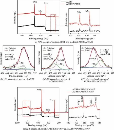
Fig. 2 XPS spectra and N1s core-level spectra of ACBF, ACBF/APTMS, ACBF/APTMS/Co2+/Ni2+ and ACBF/APTMS/Co0/Ni0.
The surface morphologies of fabric samples observed by FE-SEM were demonstrated in Fig. 5 to further illustrate the success of modification, activation and deposition on ACBF.As is shown in Fig. 5(a), the perpendicular aramid fibers and the horizontal carbon fibers constructed the plain weave networks of the initiate ACBF fabric. The fabric substrate had a smooth surface overall and only a few aramid filaments were reeled off because of the friction. There was no obvious alteration on the surface of the substrates after APTMS selfassembly(Fig.5(b)),which demonstrated the mildness of modification.Whereas the surface became rough and tiny spherical particles emerged on surface when introducing Co NPs and Ni NPs on ACBF substrates (Fig. 5(c)). This phenomenon confirmed the occurrence of Co2+and Ni2+absorption and subsequent reduction reaction. Nodule-like Co NPs and Ni NPs adhered to the ACBF substrates tightly as seeds facilitated the deposition of Co Ni alloy coating. The uniform and compact Co-Ni alloy coatings were observed in Fig. 5(d).The adhesion of ACBF substrate and alloy coating is guaranteed, which can be attributed to Van der Waals forces and strong chemical bonding between APTMS and metallic NPs.Fig. 5(e) showed the SEM image of the ACBF/Co-Ni crosssection, where the ACBF surface was covered with the Co-Ni alloy coating with a thickness of 1196 nm.
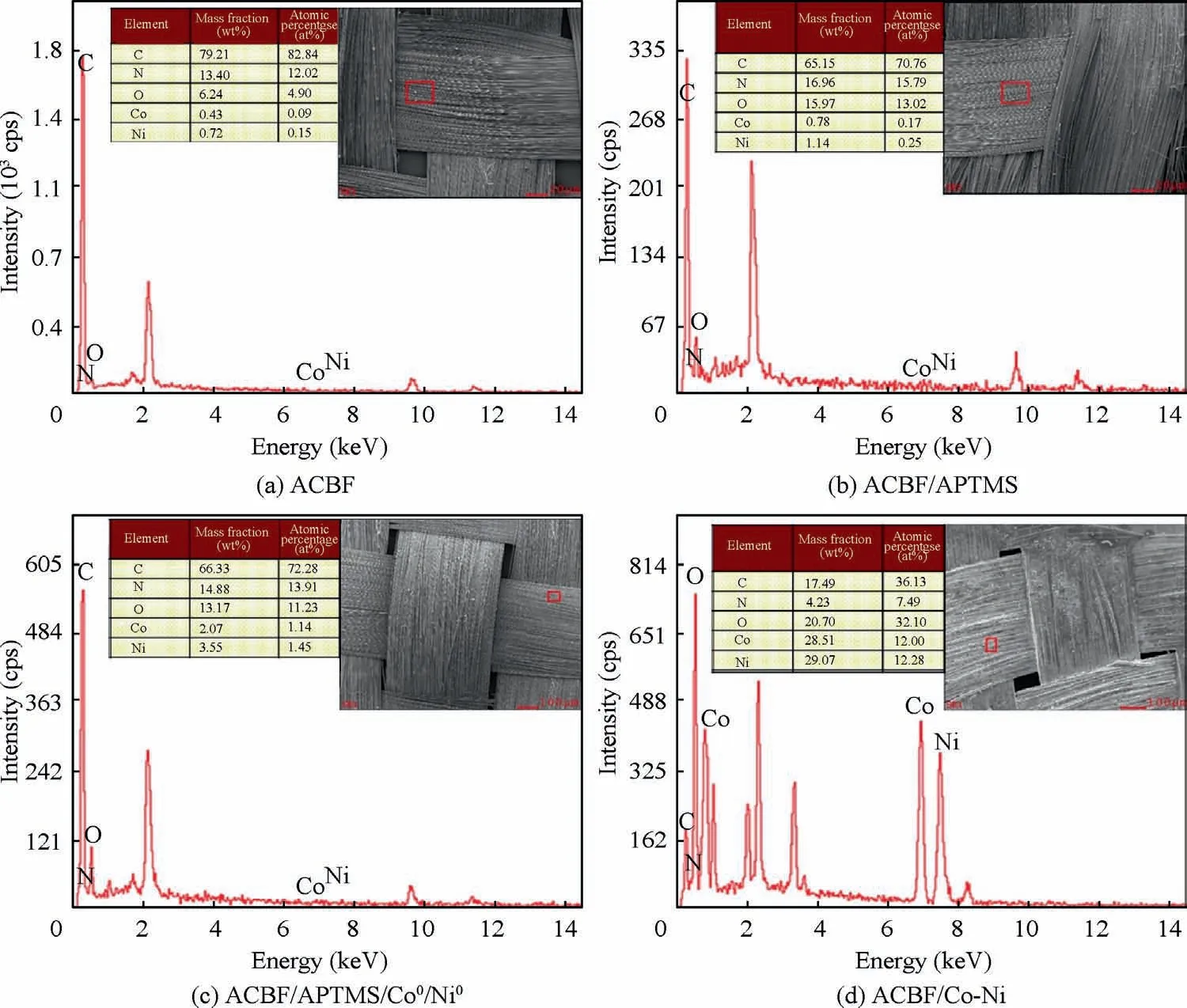
Fig. 3 EDX analysis results of ACBF, ACBF/APTMS, ACBF/APTMS/Co0/Ni0 and ACBF/Co-Ni.
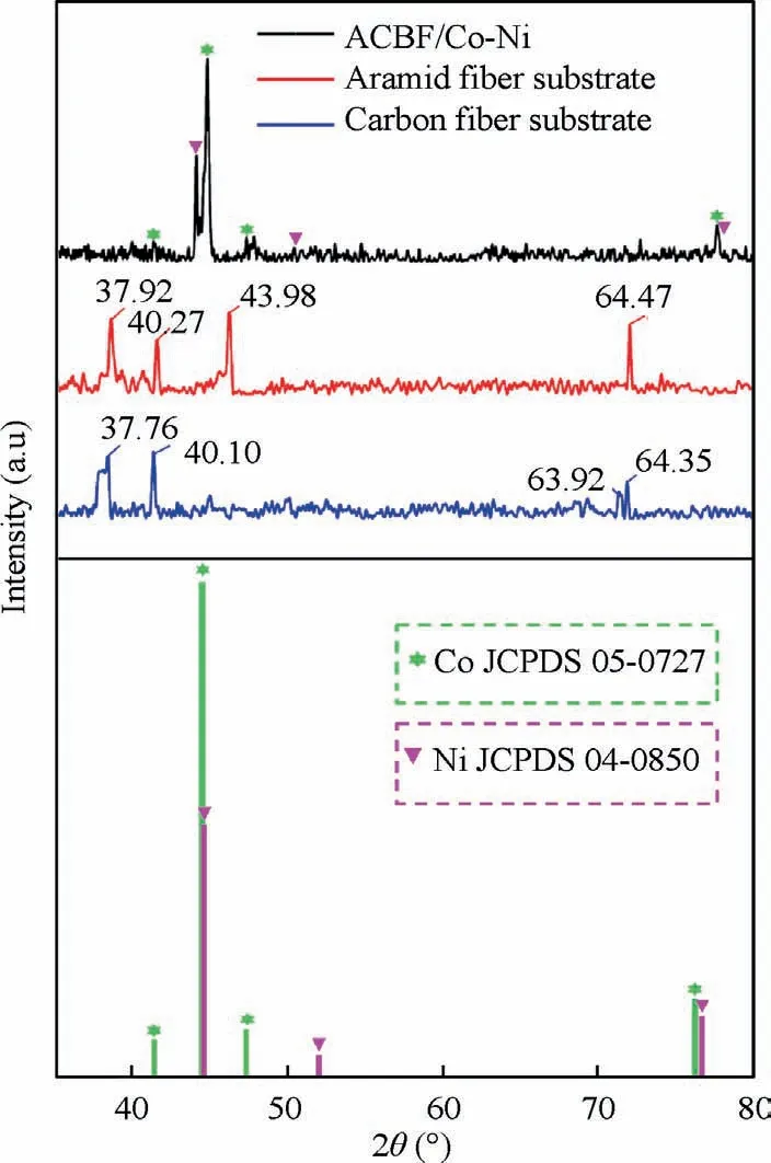
Fig. 4 XRD patterns of ACBF/Co-Ni, aramid fiber substrate and carbon fiber substrate.
Fig. 6 illustrated the potentiodynamic polarization curves of optimized Co-Ni coatings in 3.5wt% NaCl solution,10.0wt%NaOH solution and 10.0wt%HCl solution at rtwith the aid of CHI660e electrochemical workstation. Herein, corrosion current density (Icorr) was calculated by extrapolating the linear portions of the cathode and anode Tafel curves to obtain the intersection of the two lines.The dynamic potential curves of Co-Ni coatings under different conditions had similar shapes due to the fact that for all polarization curves.The anode side was dominated by active reactions while the cathode side was dominated by oxygen reduction. Relevant parameters including corrosion potential(Ecorr)and corrosion current density were calculated and summarized in Table 3.The alloy coatings exhibited the best corrosion resistance(-518 mV) and corresponding minimum corrosion current(6.61×10⁻⁶A/cm2)in the NaOH solution.The corrosion resistance of the sample in hydrochloric acid and sodium chloride solution was slightly inferior due to the presence of Cl-which hindered or even destroyed the formation of the passivation film. Nevertheless, the overall corrosion resistance was favorable to meet the needs under different service environments.Theoretically,the incident EM radiations will be attenuated in three ways:Reflection loss(subscript‘‘R”),Absorption loss(subscript ‘‘A”), and internal Multiple Reflections (subscript‘‘MR”). SE is commonly applied to evaluate the total loss of EM radiations and can be formulated as

SERloss is dependent on the impedance mismatch between shielding materials and free space, and the relationship is addressed as

where Z0and Z1represent the impedance for the surface of fabric samples and the free space, respectively. The sharper impedance mismatch will give rise to a larger reflection attenuation while in an extreme situation,if the characteristic impedance of shielding material is close to that of the free space(377 Ω∙sq-1), there would be almost no reflection loss. Therefore,the Rsof ACBF/Co-Ni is measured and the value is only 0.352 Ω∙sq-1, which demonstrates that the impedance mismatch between ACBF/Co-Ni and free space is relatively high.The conductivity properties of the control samples (aramid/Co-Ni and carbon/Co-Ni) and bare ACBF were displayed in Table 4.As a result,the SE value of ACBF/Co-Ni is supposed to be higher than that of bare ACBF due to the loading of metals, which is wave-reflection dominant materials (i.e. introduced reflection loss). SEAis related to dielectric loss,magnetic loss and the matching degree between them, which is given as
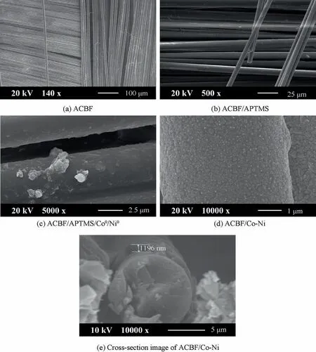
Fig. 5 SEM images of ACBF, ACBF/APTMS, ACBF/APTMS/Co0/Ni0 and ACBF/Co-Ni.
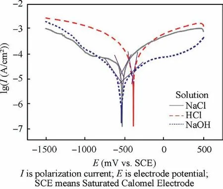
Fig. 6 Potentiodynamic polarization curves of optimized ACBF/Co-Ni in 3.5wt%NaCl solution,10.0wt%NaOH solution and 10.0wt% HCl solution at rt, respectively.

Table 3 Corrosion characteristics of electroless Co-Ni coatings in three solutions.

Table 4 Comparison of conductivity of ACBF, aramid/Co-Ni, carbon/Co-Ni and ACBF/Co-Ni.

where d and δ are the thickness of ACBF/Co-Ni and the skin depth where incident EM wave energy is attenuated to 1/e of the original radiations, respectively; r is the magnetic permeability;ω is the angular frequency of EM wave.A high dielectric/magnetic loss match level is beneficial to SEAvalue improvement. The ACBF substrate had few magnetic losses since aramid and carbon fibers lack magnetic dipoles, and thus,the main absorption loss of the ACBF substrate is mainly responsible for dielectric loss. Notably, there is no dielectric loss in bare aramid fabrics because it is intrinsically not conductive. After Co-Ni deposition, abundant magnetic dipoles were appeared in Co-Ni alloy coating, which resulted in the magnetic loss. Hence, the dielectric/magnetic loss match level was upgraded by depositing Co-Ni alloy coating on the ACBF substrate, which definitely promoted SEAvalue. Besides SERand SEAvalues, SEMRvalue of the shielding material can be neglected when SEtotalis over 15 dB.The shielding mechanism of the as-made ACBF/Co-Ni was illustrated in Fig. 7(a) and(b).
The SEtotalvalues of ACBF/Co-Ni, bare ACBF substrate,carbon/Co-Ni and aramid/Co-Ni in the frequency ranging from 30 MHz to 6.00 GHz were plotted in Fig.7(c).Generally,the SEtotalwas over 40 dB medially (42.57 dB at average) for ACBF/Co-Ni, which was obviously higher than that of bare ACBF substrate and aramid/Co-Ni. The highest SE value of coated carbon fabric indicated that the combination of carbon fibers in the substrate and Co-Ni alloy coating on top made a great contribution to higher EMI shielding performance of ACBF/Co-Ni. As shown in Fig. 7(d), the network-like substrates had a plurality of nodes,which divided the surface into flat pieces and concave pieces. The Co NPs and Ni NPs were more likely to adhere to the recessed portions in electroless plating process, so that conductive paths inside the interphase of the shielding material were increasingly constructed.Therefore, EM energies could be attenuated by leaking currents or reducing heat loss to achieve EM shielding.On the other hand,network-structured ACBF substrates expedited the distribution and assisted tremendous active sites for Co NPs and Ni NPs. Briefly, the characteristics that contributed to the compactness of metallic coatings with high conductivity led to the commendable EMI shielding performance. The SERand SEAof ACBF/Co-Ni were documented in Fig. 8. The value obtained by adding the two was evidently smaller than the SEtotalof ACBF/Co-Ni, which strongly proved that the absorption-reflection synergistic effect of carbon fibers and Co-Ni alloy coatings enhanced the EMI shielding performance. In accordance with the requirements for EMI textiles formulated by the Committee for Conformity Assessment of Accreditation and Certification on Functional and Technical Textiles, the ACBF/Co-Ni could be classified to the‘‘AAAAA” grade (99.99% EM wave could be decayed when propagated through the shielding materials) for general use,such as casual wear, office uniform, maternity dress, apron,consumptive electronic products and communication-related products, and other new applications.40The comparison of SE values in literature and in our work were summarized in Table 5, which showed that the as-made ACBF/Co-Ni had enormous potential for EMI shielding application.
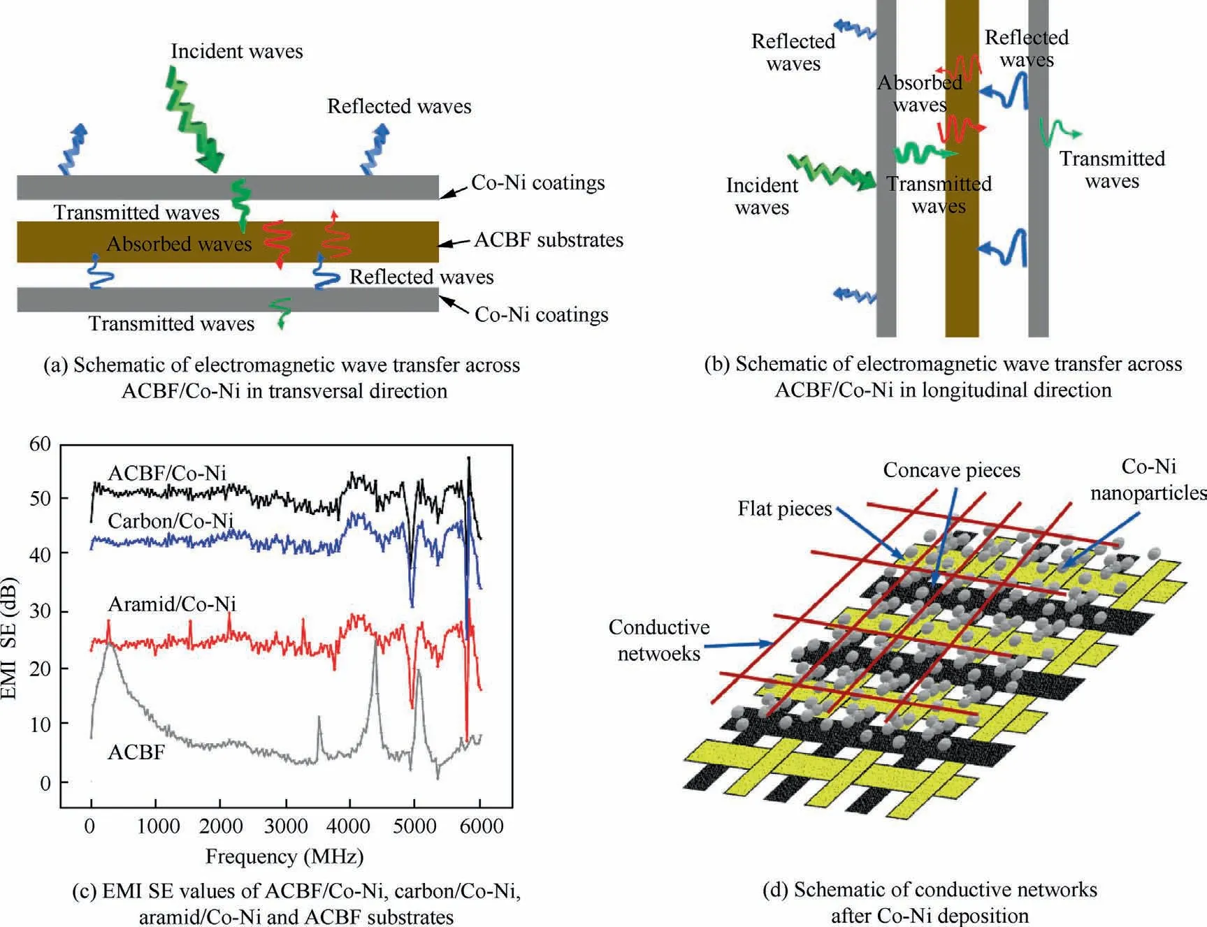
Fig. 7 EMI SE values and schematic of conductive networks after Co-Ni deposition, electromagnetic wave transfer across ACBF/Co-Ni.
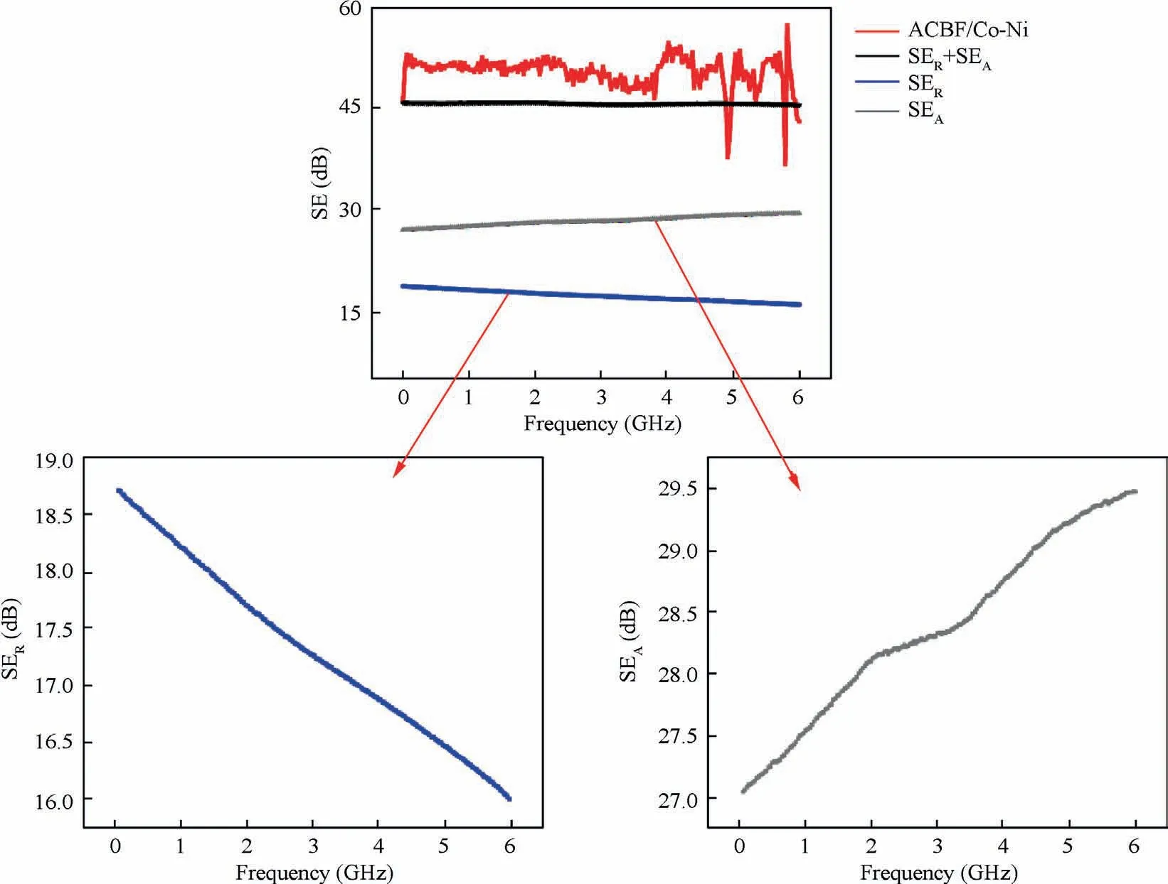
Fig. 8 SER and SEA of ACBF/Co-Ni.
The tensile tests were carried out to record the stress–strain curves (shown in Fig. 9) of Co-Ni alloy coated and the bare fabrics respectively. In order to prevent the samples from slipping due to excessive tension, epoxy resin glue was applied to the edge of fabric samples before characterization to increasethe friction between the samples and the clamps. As shown in Fig. 9, the fracture stress and elongation at break of ACBF/Co-Ni samples reached 72.9 MPa and 4.1%, higher than that(64.6 MPa and 2.3%) of carbon/Co-Ni. A large number of benzene rings in aramid molecules make the molecular chain of polymer very rigid and molecules arranged almost in parallel through powerful hydrogen bonding interaction. Consequently, aramid fiber possesses a relatively high tensile strength and is widely used as ballistic materials. Thereby,weaving aramid fibers into carbon fabric is certainly capable of enhancing the mechanical performance. In addition, the intrinsic toughness of Co-Ni alloy coating will further facilitate the tensile strength of ACBF/Co-Ni.
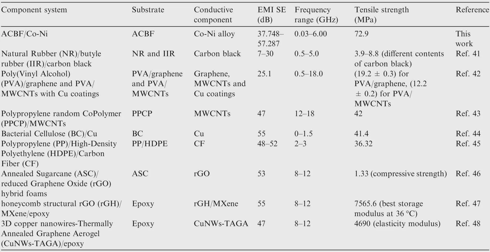
Table 5 Comparison of the different composites for mechanical EMI shielding application.
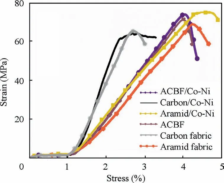
Fig. 9 Stress–strain curves of ACBF/Co-Ni, carbon/Co-Ni,aramid/Co-Ni, ACBF, carbon and aramid fabrics.
Systematically comparison in characteristics including electromagnetic shielding performance and mechanical properties is summarized in Table 5. The proposed ACBF/Co-Ni with relatively high EMI SE may provide guidelines for practical EMI applications. Notably, the resultant ACBF/Co-Ni did not need to be modified by acidification or alkalization, and the complete preparing process could be completed in no more than 2 h or 3 h. Hence, the methodology of ACBF/Co-Ni is low-cost and industrially viable.
4. Conclusions
Co-Ni alloy coated ACBF conductive fabrics with enhanced EMI shielding properties and mechanical strength was obtained in this work. The aramid and carbon blend fibers were woven into a plain weave to obtain the pristine ACBF substrates. The ACBF was subjected to APTMS modification to facilitate the chemical bonding between the substrates and metallic coatings for adhesion promotion. Co and Ni cations were absorbed in the modified substrates and reduced to Co0and Ni0by NaBH4,which provided active sites for subsequent metallic coating. The chemical states of samples during the above pretreatment were characterized by XPS. Co-Ni alloy was deposited on the substrates by cost-effective and timesaving electroless plating method.EDX and SEM were utilized to analyze the elemental variations and morphologies of fabric sample in results confirmed that the coatings were homogeneous and compact.
(1) ACBF/Co-Ni exhibited high corrosion potential in acidic, neutral and alkaline solutions (-498, -477,-518 mV), respectively, demonstrating its excellent corrosion resistance.
(2) ACBF/Co-Ni samples performed high EMI SE values reaching 37.748–57.287 dB at the frequency range from 30 MHz to 6000 MHz, which was attributed to the carbon-Co-Ni-ternary system inducing reflection and absorption loss together.
(3) The synergistic effect of carbon fibers and aramid fibers in the substrate for ACBF/Co-Ni enhanced EMI shielding performance and mechanical properties mutually.
(4) The enhanced fracture stress and elongation break of ACBF/Co-Ni reached 72.9 MPa and 4.1% respectively.
Notably, there is no need to modify the ACBF/Co-Ni by acidification or alkalization, and the complete preparing process can be accomplished in no more than 2 h or 3 h. Overall,the proposed ACBF/Co-Ni with relatively high EMI SE and tensile strength may provide guidelines for practical wearable electronics.
Declaration of competing interest
The authors declare that they have no known competing financial interests or personal relationships that could have appeared to influence the work reported in this paper
Acknowledgements
This work was supported by the National Natural Science Foundation of China (No. U1830108), the Shanghai Natural Science Foundation, China (No. 20ZR1405000), the Innovation Foundation of Shanghai Aerospace Science and Technology, China (No. SAST2018-061) and the Exploratory Research Project of ‘‘Yanchang Petroleum (Group)-Fudan University”, China.
 CHINESE JOURNAL OF AERONAUTICS2021年10期
- CHINESE JOURNAL OF AERONAUTICS的其它文章
- Direct dynamic-simulation approach to trajectory optimization
- A strong robustness open-circuit fault diagnosis strategy for novel fault-tolerant electric drive system based on d-q-axis current signal
- Nonlinear vibration response characteristics of a dual-rotor-bearing system with squeeze film damper
- Ground maneuver for front-wheel drive aircraft via deep reinforcement learning
- Numerical simulation of a UAV impacting engine fan blades
- Recent advances in precision measurement &pointing control of spacecraft
