Preparation of CF/Ni-Fe/CNT/silicone layered rubber for aircraft sealing and electromagnetic interference shielding applications
Wanying LUAN, Qin WANG, Qi SUN, Yinxiang LU
Department of Materials Science, Fudan University, Shanghai 200433, China
KEYWORDS Electroless plating;Electromagnetic interference shielding;Heating effects;Nickel-iron (Ni-Fe) coating;Sealing rubber
Abstract To meet the needs of preventing information leakage in space engineering and military industry, an efficient method was introduced to obtain layered electromagnetic shielding sealing rubber.The carbon fiber,Ni-Fe coating,and Carbon NanoTube(CNT)were combined by chemical plating and in-situ polymerization to obtain a lightweight (0.14 g/cm2) and thin (1 mm thick) Carbon fiber Fabric (CF)/Ni-Fe/CNT/silicone layered electromagnetic shielding composites. The layered material obtained by adjusting the electroless plating time exhibited a high Shielding Efficiency (SE) of 60.2–85.5 dB in the range of 0–4800 MHz, which can be used for aviation electromagnetic shielding. Carbon fibers and carbon nanotubes mainly attenuated electromagnetic waves through absorption loss,while the nickel-iron alloy coating through reflection loss interacted with the magnetic vector of incident ElectroMagnetic (EM) radiation and magnetic dipoles, therefore, the EM Interference (EMI) shielding composite attenuated EM waves with the ‘‘absorptionreflection-absorption”cooperative interaction.Moreover,the flexible fabric substrate adhered with silicone rubber possessed a breaking elongation of 52.3%, which can be utilized as a good sealing material.Simultaneously,the outstanding exothermicity(67.2°C under the applied voltage of 5 V)makes it possible to be applied in electric heating area. The electromagnetic shielding composites prepared in this paper have good potential in the fields of precision electronic equipment and aviation systems.
1. Introduction
The aircraft is equipped with radar,communication and other electronic instruments,which will generate strong ElectroMagnetic Interference(EMI)and radio frequency interference during operation. Electromagnetic shielding rubbers are used in aircraft equipment cabins, skins, covers and electronic equipment to ensure the working accuracy of a large number of electronic systems in the cabin while the aircraft is flying.1The flight environment of the aircraft is very harsh,which requires the rubber seals to work for a long time in the temperature range of –75–200°C and resist ozone complex ambient conditions. Therefore, there are high requirements for the substrate of the electromagnetic shielding rubber.
At present, various polymer-based functional composite materials have been widely fabricated via adding reinforcing materials into polymer matrices, such as epoxy,2–5polyvinylidene fluoride,6polyaniline,7,8silicone rubber,9waterborne acrylic resin10and natural polymer like sodium carboxymethyl cellulose,11acquiring perfect conductivity, friction resistance and other properties. Among them, silicone rubber is an elastomer with a repeating structure of [SiRR’]O- groups. This structure gives silicone rubber many unique properties,including nontoxicity, low cost, ease of fabrication, desirable chemical corrosion resistance, temperature resistance, ideal UltraViolet(UV)resistance and mechanical stability in a wide range of temperature and humidity, etc.12–16In addition, the outstanding flexibility and resilience of silicone rubber make it a good matrix for sealing materials.17These properties which are able to cope with the rough working environment of aircraft make silicone the most promising aviation EMI rubber substrate.However,its relatively low strength limits it to a narrow application range. In order to improve its strength and abrasion resistance, silicone rubber is often compounded with reinforcements(such as fibers)to prepare composite materials.When applied to electromagnetic shielding, electromagnetic shielding materials can be used to enhance the EMI Shielding Effectiveness (SE).
According to EMI shielding theory, EMI shielding materials attenuate electromagnetic waves by three mechanisms, i.e.reflection loss,adsorption loss,and internal multiple reflection loss.18Metal is a typical reflection loss dominant material due to its excellent electrical conductivity,for the internal free electrons can interact with the electric field components in the electromagnetic field. Metals with high electrical conductivity including silver, gold and aluminum are widespread EMI shielding materials.19,20Absorption loss depends on interactions between the electric or magnetic dipoles and electromagnetic fields. Currently, commonly used absorption loss dominant materials include magnetic materials with magnetic permeability (such as Ni, Co, Fe3O4, γ-Fe3O4, and CoFe2-O4),21–23ferroelectric ceramics with high dielectric constant(e.g. ZnO, TiO2, and BaTiO3),18,24carbon-based materials(carbon fibers, carbon black, graphene, carbon nanotubes,etc.),20,25–29and intrinsically conductive polymers materials(polyaniline,polypyrrole,etc.).30,31For instance,Wang et al.32assembled conductive cellulose nanofibers/Ti3C2TxMXene aerogels with epoxy matrix, whose EMI SE reached 75 dB.Absorption loss dominated the shielding mechanism owing to its highly conductive porous networks. Song et al.33constructed reduced Graphene Oxide (rGO)/epoxy nanocomposites with honeycomb structure, which achieved high conductivity(387.1 S/m)and EMI SE(55 dB).Multiple reflections attenuate electromagnetic wave by reflections at multiple interfaces. To achieve effective multiple reflection loss, porous foam with large surface areas is applied frequently.34The multiple reflection contributes very little and usually can be neglected (if absorption is greater than 10 dB). In practical application, EMI shielding materials with different shielding mechanisms are often combined through reasonable optimization design, which can increase the cooperative interaction of the shielding materials and greatly improve the EMI SE. For example, Wu et al.35fabricated hierarchical porous cobalt(Co)/carbon (C) crabapples with facile solvothermal reaction coupled and carbon reduction treatment.The system presented outstanding absorption with an optimal reflection loss RLof 56.9 dB at 9.3 GHz and a broad absorption bandwidth due to the improved impedance matching level of porous Co/C crabapples resulting from the synergy of cobalt and carbon.Composite consisting of porous carbon matrix and nickel nanoparticles constructed by Xie et al.36achieved strong reflection loss and broad bandwidth (13.6–18.0 GHz),which attributed to the dielectric relaxation loss of the multilevel carbon structure and ferromagnetic resonance of the nickel nanoparticles. Yang et al.37prepared Copper NanoWires-Thermally Annealed Graphene Aerogel (CuNWs-TAGA) framework by freeze-drying and thermal annealing, which exhibited EMI SE of 47 dB and electrical conductivity σ of 120.8 S/m owing to its 3D CuNWs-TAGA conductive network structures.
Divided by structure, electromagnetic shielding composite materials mainly include doped and layered materials. Doped EMI composite material refers to filling conductive matrix such as metal particles or carbon-based conductive filler into the polymer matrix. For example, Li et al.38dispersed graphene into styrene-butadiene rubber with the volume fraction of graphene being 30%.The tests showed that the conductivity of conductive rubber was 219 S/m, and the electromagnetic shielding effectiveness reached to 45 dB at 8–12 GHz. Xiao et al.39studied the electromagnetic shielding and mechanical properties of conductive silicone rubber filled with nickel powder and silver-plated nickel powder.The electromagnetic SE of silver-plated nickel powder rubber reached twice as much as that of nickel powder-filled rubber.However,doped composite materials have certain disadvantages. Metal fillers have a high density,which makes it hard to achieve lightweight.40Carbonbased filler composites have insufficient conductivity to meet the high SE requirements of aerospace instruments (60–90 dB).41In addition, the uniformity of filling material is hard to control, and the addition of dispersant may reduce the mechanical properties of the material. Layered EMI shielding composite material generally refers to the composite of the shielding intermediate layer and the substrate layer,the manufacture of it only needs to apply a polymer coating by polymerization or deposit a metal layer by electroless plating or electroplating on the substrate surface.42,43Compared with doped material, layered shielding materials show better electromagnetic shielding performance, which is proved by the comparative studies conducted by Fu et al.44Simultaneously,the experimental operation of layered EMI material is convenient to attain macro-controlled materials with uniform properties, and the mechanical properties of the material can be improved simply by adjusting the intermediate layer.45Hence the properties of EMI shielding composites like electromagnetic shielding effectiveness and mechanical properties can be achieved through layered structure and the synergy of various electromagnetic shielding materials.
In this paper,a conductive fabric was compounded with silicone rubber to fabricate electromagnetic shielding composites with ‘‘absorption-reflection-absorption” cooperative interaction.Carbon fiber fabric was used as the substrate and deposited with magnetic alloy nickel-iron (Ni-Fe) on it, and then it was compounded with a silicone rubber doped with carbon nanotubes (10 wt%). First, the carbon fiber fabric was modified with 3-AminoPropylTriMethoxySilane (APTMS) and activated with Ni0.Then Ni-Fe alloy was deposited on the fabric by electroless plating.Finally,a silicone coating doped with carbon nanotubes was obtained on metallized fabric by in-situ polymerization. Fourier Transform InfRared (FT-IR) spectroscopy and X-ray Photoelectron Spectroscopy (XPS) tests were performed on the samples to study the fabric modification and electroless plating activation processes. X-Ray Diffraction (XRD) and Field Emission Scanning Electron Microscopy (FE-SEM) tests were used to observe the morphology and element composition of the coating surface at different deposition stages. Tests of EMI SE and thermal performance were carried out by Vector Network Analyzer(VNA) and pyrometer, respectively.
2. Experiment
2.1. Chemical products and materials
Carbon fiber fabric(gram weight 200 g/m2)was cut to a size of 10 cm×10 cm before preparing samples. The solutes used in the electroless plating solution, such as nickel sulfate hexahydrate (NiCl2∙6H2O), potassium sodium tartrate (KNaC4H4-O6), sodium hypophosphite (NaH2PO2∙H2O), etc., were purchased from Sinopharm Chemical Reagent Co., Ltd. Four ferrous chloride hydrate (FeCl2∙4H2O) was purchased from Shanghai Wokai Chemical Reagent Co.,Ltd.Sodium borohydride (NaBH4) was purchased from Shanghai Chemical Reagent Co.,Ltd.and used as a reducing agent in the electroless plating bath. Silicone was purchased from Austen State Corporation. All reagents in the experiment are of analytical grade and can be used directly. Deionized water (resistivity is 18.2 MΩ∙cm) was utilized for the solutes and rinses in the experiments.
2.2. Electroless Ni-Fe alloy plating on carbon fiber surface
The surface modification was first performed to improve the wettability and increase the active functional groups on carbon fiber surface, and thus to enhance the chemical bonding with metal nanoparticles. The carbon fiber fabric washed with deionized water was immersed in 100 mL of 0.125% silane coupling agent (APTMS) solution at room temperature for 15 min, and heated at 120°C for 10 min. We repeated three times and obtained a uniform APTMS coating. The modified carbon fiber fabric sample was abbreviated as CF-NH2.Afterward, a Ni-Fe alloy was deposited on carbon fiber fabric surface by a two-step electroless plating method as follows:
(1) The CF-NH2sample was soaked in a saturated Ni2+ion solution for 30 min to chelate with Ni2+cations on its surface. This fabric sample was referred to as CF-Ni2+.
(2) The CF-Ni2+fabric was immersed in 0.5 mol/L NaBH4solution at room temperature for 30 min, in order to reduce Ni2+ions to Ni0nanoparticles in situ (abbreviated as CF-Ni0). Rinse the fabric with deionized water to remove the residual Ni0nanoparticles to avoid contamination of subsequent solutions.
(3) The CF-Ni0fabric was immersed in an electroless Ni-Fe alloy plating solution at 75°C (the formula and process of electroless Ni-Fe alloy are shown in Table 1). Ni-Fe alloy was autocatalytically deposited by Ni0nanoparticles, and the deposition time was controlled at 30 min,60 min or 90 min.This fabric sample was simply referred to as CF/Ni-Fe(CF/Ni-Fe-30,CF/Ni-Fe-60 and CF/Ni-Fe-90, respectively). Finally, the fabric was rinsed with deionized water and dried in an oven at 50°C for 30 min. Compared with the carbon fiber fabric, the obtained fabric possessed enhanced hardness, but can still be folded, deformed and cut at will.
2.3. In-situ polymerization of CNT-filled silicone
In order to protect the corrosive metal coating and improve the electromagnetic shielding effectiveness of the composite material, the surface of the metalized carbon fiber fabric was coated with a layer of Carbon NanoTube(CNT)-filled silicone.The A glue and the B glue of the silicone potting compound 195 were mixed uniformly at a mass ratio of 10∶1, and then the CNTs were filled with a mass fraction(wt%)of 10%.After being stirred evenly,it was applied on both sides of the CF/Ni-Fe fabric sample by coating method and cured at room temperature for 5 h to obtain a layered composite material with a thickness of 1 mm. The layered sample was labeled as CF/Ni-Fe/CNT/silicone, which has elasticity as silicone and can be bent or deformed arbitrarily. The workflow schematic diagram of CF/Ni-Fe/CNT/silicone is illustrated in Fig. 1.
2.4. Characterization
Prior to all characterization,fabric samples were processed for 24 h in accordance with ASTM D1776-04 (temperature (20±2) °C, relative humidity (65±2)%). FT-IR spectroscopy was implemented using Thermo Scientific IS5. XPS spectrum was tested by X-ray photoelectron spectrometer (ThermoFischer, ESCALAB 250Xi). The excitation source was Al kα ray (energy hv=1486.6 eV) at 12.5 kV and 16 mA, and the signal was accumulated for 10 cycles. Peak fitting was performed using XPSPEAK 4.1 software, based on the Shirleytype background subtraction method and with a Gaussian/Lorentzian ratio of 20%.FE-SEM(S-4300SE,Hitachi,Japan)was used to characterize the surface morphology of the fabric samples in different steps, and an Energy Dispersive X-ray Spectroscopy (EDS) was coupled to analyze composition.Before characterization, a fabric sample for SEM observation was deposited on a sample holder with a sticky carbon ribbon,and a platinum layer of about 5 nm thickness was sputtered.The XRD diffractometer (Rigaku Dymax Japan) with Cu Kα radiation (wave length λ=1.54056 A˚) was utilized to study the crystal characteristics of the fabric samples. The voltage and current of the X-ray tube were 40 kV and 40 mA, respectively,and the scanning range was 20°–80°with a scanning rate of 5 (°)/min. A Vector Network Analyzer (VNA, DRS02)coaxial transmission line method was used to record the EMI SE of fabric samples obtained in the frequency range of 0–4800 MHz. Before starting the EMI measurements, the instrument was auto-calibrated.The samples were cut into circles with a radius of 7.5 cm according to the size of the device,and placed between the two fixtures for testing. According to the waveguide method in the X-band (8.2–12.4 GHz) region,the scattering parameters(S11,S22,S12,and S21)of the conductive fabrics were measured on HP8510C VNA.The fabric samples were slit into rectangular pieces with dimensions of 22.9 mm×10.2 mm to accommodate the X-band waveguide holders. To further investigate the EM wave attenuation of the samples, the complex permittivity and permeability were measured by HP8510C VNA as well.
3. Results and discussion
3.1.Surface physical and chemical properties of CF/Ni-Fe fabric
Fig.2(a) shows FT-IR spectra of the original Carbon fiber Fabric (CF) and the modified carbon fiber fabric by APTMS(CF-NH2). As shown in Fig.2(a), the CF samples displayed the same infrared characteristic peak distribution before and after the modification. The stretching vibration peak of –OH, which appeared near 3439 cm-1, could be determined as the characteristic band of hydroxyl groups attached to water.The characteristic absorption peaks at 2916 cm-1and 2854 cm-1could be ascribed to the stretching vibration of the C–H bonds in the methyl, methylene and methoxy groups of the carbon fiber random layer graphite structure.The strong absorption peak at 1090 cm-1was caused by the stretching vibration of C–O in alcohol phenols, which corresponded to the carbon fiber fabric sizing agent. The absorption peaks at 1590 cm-1and 539 cm-1attributed to the stretching vibration of the C–N bonds and the bending vibration peak between N–H indicated that the silane coupling agent (APTMS) successfully attached –NH2on the surface of carbon fiber fabric. It could be seen that after modification,almost all the characteristic peaks on the fabric substrate were retained, which revealed that the silane coupling agent(APTMS)modification was a relatively mild chemical reaction process, without destroying the molecular chemical structure of the fabric.
XPS wide scanning spectra of the pristine carbon fiber fabric (CF), modified carbon fiber fabric (CF-NH2), Ni2+adsorbed carbon fiber fabric(CF-Ni2+),and Ni0activated carbon fiber fabric(CF-Ni0)were illustrated in Fig.2(b).Characteristic peaks of C1s and O1s could be observed at 288.4 eV and 534.5 eV, respectively, which was corresponding to the main elements of the fabric. The content of elements on the surface of the fabrics was shown in Table 2.Comparing curve of CF-NH2to curve of CF, we can see that after the APTMS modification treatment, the characteristic emission of Si element appeared at 153.5 eV and 102.8 eV. Simultaneously, the molar ratio of N element (binding energy is 398.4 eV) significantly improved from 3.02 to 4.54 due to the adhesion of –NH2to the carbon fiber fabric. The result confirmed that the APTMS molecules were introduced to the CF substrate surface. After the electroless plating, Cl and Na doping element signals were found at 198.6 eV and 63.1 eV in the narrow spectrum within the binding energy of 0–230 eV, which derived from the FeCl2∙4H2O and NaH2PO2∙H2O in electroless plating solution. A photoelectron peak belonging to Ni could be signed at a binding energy of about 852.6 eV in full-scanning XPS spectrum of the CF-Ni0fabric, which proved that the Ni0nanoparticles were successfully adsorbed on the fabric surface.

Table 2 Contents of surface elements of CF, CF-NH2, CFNi2+, CF-Ni0 fabrics.
To confirm the crystalline structure of the fabric samples CF and CF/Ni-Fe(30 min,60 min,90 min),XRD were carried out and the corresponding patterns are displayed in Fig.3.The peak at 2θ=25.50°corresponded to the characteristic peak of graphite crystal (0 0 2) in the original carbon fiber fabric, and the diffuse scattering peak was verified as the random layer graphite structure of the carbon fiber substrate. After the Ni-Fe coating co-depositing on the surface of the substrate, the composite fabric exhibited Bragg reflection at 2θ=44.57°,51.79°, 75.54°, corresponding to the Face Centered Cubic(FCC) Ni (1 1 1), Ni (2 0 0), and Ni (2 2 0) crystal planes,according to the standard card JCPDS 04-0850.In accordance to the standard card JCPDS 06-0696, the crystal peaks shown at 2θ=44.57°, 64.90° corresponded to the Fe (1 1 0) and Fe(1 0 0)crystal planes of the Body Centered Cubic(BCC)structure. However, due to the small content, the characteristic peaks of Fe could not be displayed obviously. Meanwhile,no signal was observed for impurities in oxidation state (such as NiO and Fe2O3) or hydroxide state (such as Fe(OH)2and Ni(OH)2). It is worth noting that, after Ni-Fe co-deposition,the peak strength exhibited by the carbon fiber fabric substrate significantly decreased, and the peak value ratio of the substrate peak to Ni peak (2θ=44.57°) decreased from 1.32 to 0.75 with the increase of the deposition time. This phenomenon could be attributed to the high coverage of the Ni-Fe coating, which indicated that the alloy coating was tightly loaded on the fabric. The content and compactness enhanced with the increasing deposition time.
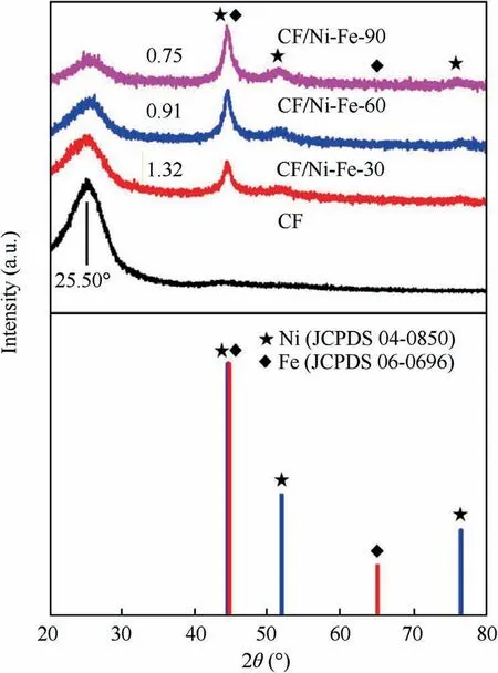
Fig. 3 XRD pattern of original fabric CF and CF/Ni-Fe fabric with electroless Ni-Fe deposited for different time.
A further justification for the phase composition of conductive fabric was carried out by deconvolution of Ni2p and Fe2p signals. Fig. 4 illustrated the high-resolution XPS spectra of Ni2p and Fe2p obtained from the samples after electroless plating. As shown in Fig.4(a), after electroless plating, three categories of patterns existed on the surface of samples: divalent nickel (binding energy is 857.8 eV), shakeup satellite signals (binding energy is 862.9 eV) and zero-valent nickel(binding energy is 853.8 eV).46Among them, zero-valent achieved a higher peak, which revealed that a large amount of Ni2+were reduced to Ni0by NaBH4. As shown in Fig.4(b), a similar result of Fe2p XPS spectra was exhibited. After electroless plating,Fe2p signal could be resolved to three components: Fe2+, satellite peak of Fe2+and Fe0at binding energy of 709.5, 717.3 and 705.1 eV, respectively.47Highresolution XPS spectroscopy proved that Ni and Fe were largely reduced from ions to atoms through the electroless plating process.
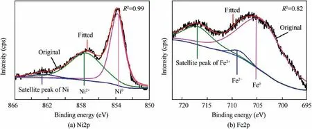
Fig. 4 Core-level XPS spectra of Ni 2p and Fe 2p obtained from CF/Ni-Fe fabrics..
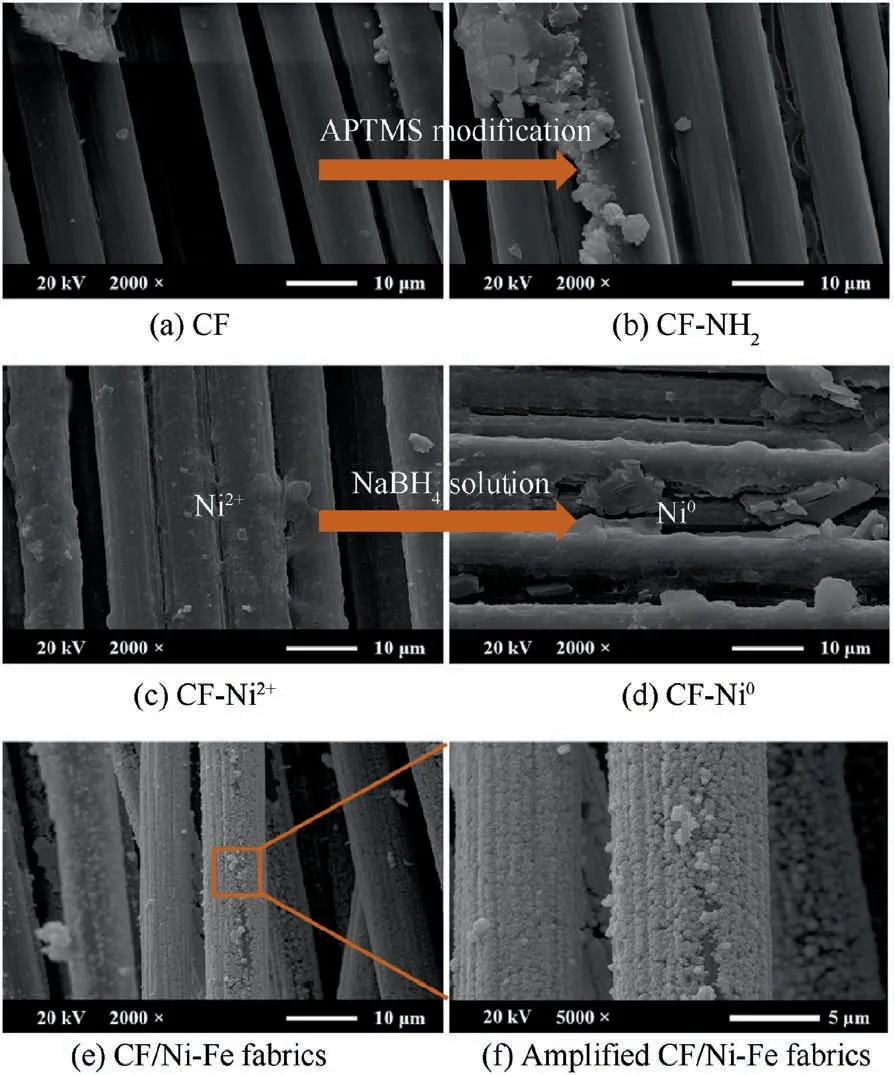
Fig.5 SEM images of CF,CF-NH2,CF-Ni2+,CF-Ni0,and CF/Ni-Fe fabrics.
The surface morphology of the fabric samples at different experimental stages were observed by SEM. Fig. 5 demonstrated SEM images of the CF, CF-NH2, CF-Ni2+, CF-Ni0fabrics.Regular longitudinal cylinders showed in Fig.5(a)suggested the smooth surface with few impurities of the original carbon fiber fabric. Carbon fibers are easily fuzzed or broken by mechanical friction during the production and processing.Therefore, an organic sizing agent layer with several tens of nanometers thick is generally coated on the surface to increase the strength. The protective layer has no effect on the characteristics of the carbon fiber. Besides, it is beneficial to the surface modification and metal deposition subsequently. After APTMS modification (Fig.5(b)), the surface of the carbon fiber fabric became rougher, where some fine grooves and irregular protrusions were observed. In Fig.5(c) and (d), the diameter of the single carbon fiber increased for the Ni2+and reduced Ni0were fixed on the surface. Fig.5(e) and 5(f)show the morphology of the plating layer after Ni-Fe alloy deposition (magnification at 2000 times and 5000 times). It could be seen that the spherical alloy aggregates almost completely covered the fabric surface to form a continuous and dense alloy layer. EDS was utilized to determine the elementary composition of the samples including CF/Ni-Fe fabric with segmented plating time and the CF/Ni-Fe-90/CNT/silicone to prove the growth of Ni-Fe and CNT. The CF/Ni-Fe fabrics were mainly composed of C, O, Ni and Fe, and the surface of CF/Ni-Fe/CNT/silicone was filled with C, O and Si. The corresponding atomic proportions were recorded in Table 3. With increasing time of plating, the surface metal content of CF/Ni-Fe fabrics augmented,especially for Ni content rising from 36.67% to 62.32%, which is consistent with the higher conductivity. Compared with the content of Ni,the content of Fe was in small quantities, which corresponds to the weak signal of Fe in XRD test. After CNT/silicone was coated, a large amount of C, O, Si signals appeared on the surface,and Ni and Fe signals were hardly detected,which indicates that the silicone layer was dense. At the end of the electroless deposition process, the metal loading L (mg/cm2)of the electroless Ni-Fe coating is calculated by

where m1and m2represent the weight of the fabric before and after electroless plating, respectively; A represents the area of the fabric sample. The deposition rate of chemical multiple alloy plating can be evaluated by

where V(mg∙cm-2∙h-1)and t represent the deposition rate and deposition time, respectively. The data obtained are shown in Table 3. It could be found that the metal loading increased with the deposition time, while the deposition rate decreased inversely. As the fabric surface was gradually covered by the alloy coatings, the decrease of the exposed active Ni0particles impeded the subsequent electroless plating reaction.

Table 3 Elemental compositions (EDS and ICP measurement), loading of metal, deposition rate, surface resistance and electrical conductivity of CF/Ni-Fe fabrics (different plating time) and CF/Ni-Fe-90/CNT/silicone.
3.2. Mechanical stability of CF/Ni-Fe/CNT/silicone layered composite materials
Taking into account the actual situations,the evaluation of the mechanical stability of the layered composite is significant.Because of the flexibility and elasticity of the attained layered composite material, folding and stretching are inevitable in practical applications. The results of mechanical properties of the product are shown in Table 4. The mechanical properties of the product have decreased after the surface of the fabric was coated with CNT-doped silicone. It was due to the lower mechanical performance of the silicone, which caused cracking during extrusion. But the layer composites were still connected into a whole with high mechanical properties. At the same time, the mechanical properties of the layered structure have been greatly improved compared to CNT-doped silicone (CNT/silicone). The coating of silicone increases the elongation at break of the sample to 52.3%, which makes the material suitable for sealing materials such as sealing rings.
3.3. Thermal performance of CF/Ni-Fe/CNT/silicone layered composites
In order to test the heating performance of the composite materials,a voltage was applied to both ends in the long direction of the sample with a size of 4 cm×8 cm.The temperature at the middle position of the sample was recorded, simultaneously.After the power was applied for 5 min,the surface temperature of the fabrics reached equilibrium.As shown in Fig.6(a), the surface temperature of CF/Ni-Fe/CNT/silicone samples could reach 51.6°C under the applied voltage of 3 V,while 67.2°C under 5 V, and it maintained stable for more than 15 min. Meanwhile, Fig.6(b) illustrates that the power density of the composite material is almost linearly related to the loading voltage (in the range of 1–5 V), so the variation of the power density with the loading voltage could be predicted. Therefore, the layered material has the potential to be used as a thermal insulation function layer and electric heating material in aviation equipment.
3.4. Electromagnetic shielding performance of CF/Ni-Fe/CNT/silicone layered composites
SE is a parameter used to quantify the performance to resist external EMI field. The total loss of EMI shielding (SEtotal,dB) consists of reflection loss (SER, dB), absorption loss(SEA,dB),and multiple reflection loss(SEM).The corresponding formula is given as

where P1and P2refer to the power density of the incident wave and the transmitted wave, respectively. The reflection loss increases with the conductivity while decreases with the permeability, which depends on their match level specifically. The absorption loss is the consolidated result of the absorption of dissipated energy of electromagnetic waves in the shielding layer,which is dependent on the interaction of the electromagnetic field with the electric or magnetic dipoles of the conductor, and increases with conductivity, permeability and thickness of shielding material. Multiple reflection loss is relevant to the internal heterogeneity of the EMI shielding material. For bulk conductive monolithic materials, Eqs. (4) and(5) can be used to determine reflection loss and absorption loss:48

where σris the electrical conductivity of the shielding layer relative to copper;μris the magnetic permeability of the shielding layer relative to free space μ0=4π×10-7H/m; f is the frequency of the electromagnetic wave; d is the thickness of the shielding material. Although Eqs. (4) and (5) are for conductive and monolithic materials, it is still possible to evaluate shielding materials for multilayer structures. Composites with negative permittivity have been demonstrated as good EMI material shielding electromagnetic wave by conduction lossand polarization loss, such as Ni/MnO nanocomposites49and graphene/PVA metacomposites.50

Table 4 Mechanical properties of coated fabrics.
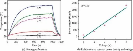
Fig.6 Heating performance and relation curve between power density and voltage of CF/Ni-Fe/CNT/silicone layered composites under an applied voltage of 1–5 V.
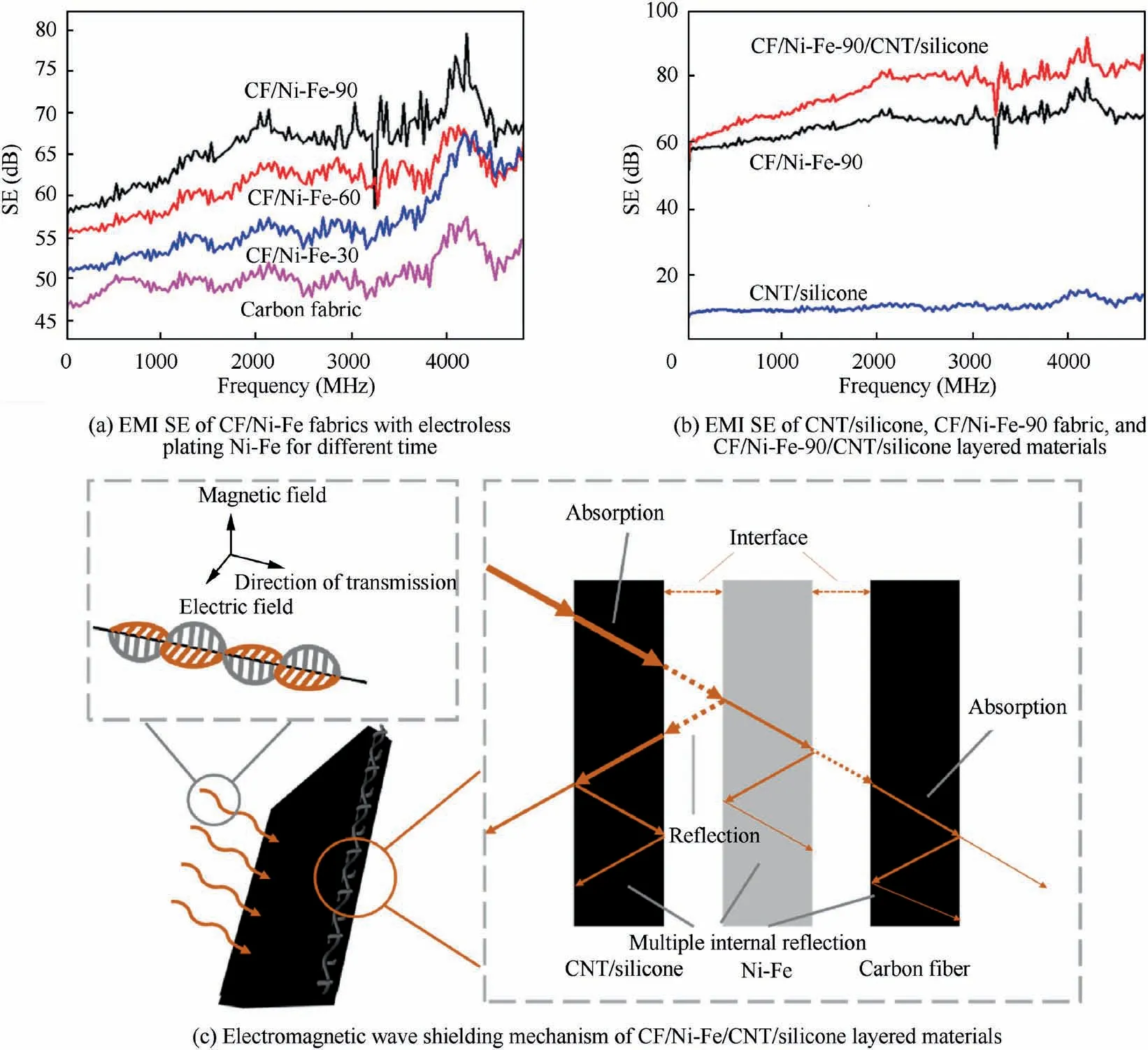
Fig.7 EMI SE of CNT/silicone,CF/Ni-Fe fabrics and CF/Ni-Fe-90/CNT/silicone layered materials and electromagnetic wave shielding mechanism of CF/Ni-Fe/CNT/silicone layered materials.
The EMI SE values of CF/Ni-Fe fabric and CF/Ni-Fe-90/CNT/silicone composites in the range of 0–4800 MHz were recorded in Fig.7(a) and (b). As the electroless plating time increased,the content of metal deposited on the fabric surface improved, bringing out boosting electromagnetic shielding effectiveness accordingly. The electrical conductivity of the fabric with electroless plating for 30, 60, 90 min were 7.479,8.298, 12.821 S/cm, respectively. The EMI SE of the samples improved with the increase of the conductivity. Among them,the EMI SE of CF/Ni-Fe fabrics with electroless plating for 90 min could reach 57.8–79.5 dB. Fig.7(b) shows the electromagnetic SE curves of CNT/silicone, CF/Ni-Fe-90 and CF/Ni-Fe-90/CNT/silicone in the frequency range of 0–4800 MHz. Compared with the CF/Ni-Fe-90 and CNT/silicone samples, the CF/Ni-Fe-90/CNT/silicone sample possessed a significantly higher electromagnetic SE (60.2–85.5 dB).This was owing to the advantages of comprehensive absorption and reflection attenuation dominant materials of CF/Ni-Fe/CNT/silicone layered composite materials, and the possible electromagnetic shielding mechanisms were illustrated in Fig.7(c).When the EM wave in free space(including air and vacuum)was incident on the one side of the layered CF/Ni-Fe/CNT/silicone sample, the part that was not absorbed completely by CNT would reach the Ni-Fe layer. Subsequently,the highly conductive alloy layer continued to attenuate the EM wave by the reflection mechanism and magnetic loss mechanism, and the inner carbon fiber fabric could hinder the EM wave from propagating by reflection as well. Moreover, the other semi-symmetrical structure further weakened the EM wave in compliance with a similar mechanism. Such a sandwich-structured layered material formed an ‘‘absorptionreflection-absorption” cooperative interaction that notably optimized the EMI shielding performance.
To clearly demonstrate the shielding mechanism of the composite, the SERand SEAportions of the prepared CF/Ni-Fe/CNT/silicone with different plating time are displayed in Fig.8(a) and (b) at the frequency ranging from 8.2 GHz to 12.4 GHz (X-band). The result validated that the shielding effectiveness of CF/Ni-Fe/CNT/silicone composites was a combination of SEAand SER. With the increase of electroless plating time, SERand SEAenhanced simultaneously, and the proportion of SERpart in the total EM attenuation improved from about 25% to about 50%. This is due to the thickness development of the Ni-Fe coating and the raising conductivity resulting in an enlargement in reflection. Herein, plenteous magnetic dipoles in the coating interacted with the magnetic vector of incident EM radiation,which brought about considerable absorption loss. Complex permittivity and permeability of CF/Ni-Fe fabric (plating time for 90 min) and CF/Ni-Fe/CNT/silicone samples were measured by Transmission/Reflection (T/R) coaxial line method to inquire into wave attenuation. For EMI shielding materials, the EMI SE is the comprehensive results of dielectric and magnetic loss factors.Fig. 9 illustrates the frequency dependence of the loss tangent of dielectric/magnetic of CF/Ni-Fe-90 fabric and CF/Ni-Fe-90/CNT/silicone samples. The loss tangent of dielectric/magnetic are expressed as tan δE=ε′′/ε′and tan δM=μ′′/μ′,respectively, to measure the magnitude of energy attenuation,where ε′′(μ′′)and ε′(μ′)represent the imaginary and real parts of the complex permittivity(permeability),respectively.Ni and Fe are typical magnetic metals exhibiting high magnetic permeability, and thus, for CF/Ni-Fe-90 fabric (Fig.9(a)), abundant magnetic dipoles inside the Ni-Fe coating brought about a high magnetic loss, which was the main reason for the absorption attenuation. After the coating of CNT/silicone(Fig.9(b)), high conductivity of CNT gave rise to increased dielectric loss of the sample.After compounding with CNT/silicone,the dielectric/magnetic loss match level improved,which contributed to the increase of absorption attenuation.
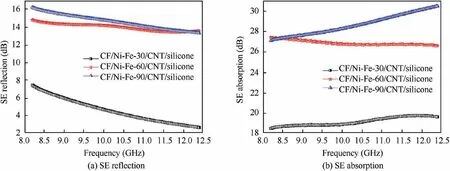
Fig. 8 SE reflection and SE absorption portion of CF/Ni-Fe/CNT/silicone with different plating time in X-band region.
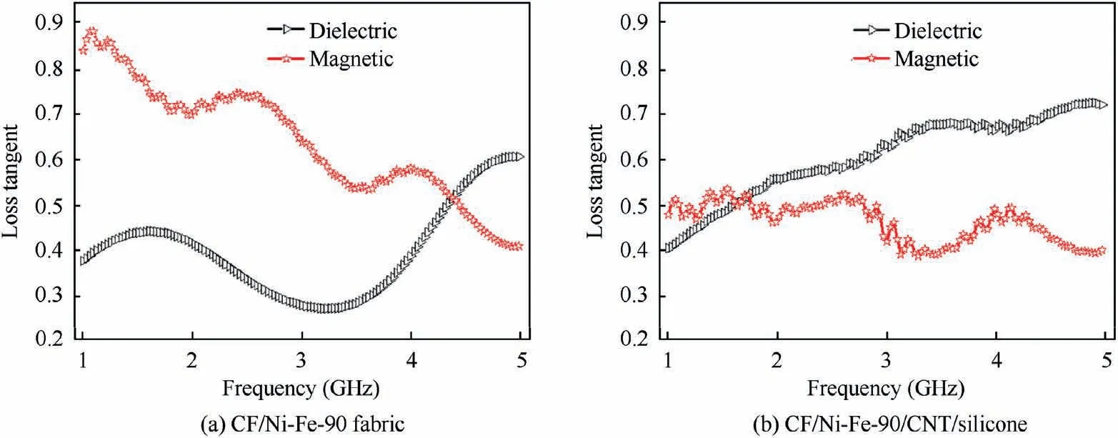
Fig. 9 Frequency dependence of the loss tangent of dielectric/magnetic of CF/Ni-Fe-90 fabric and CF/Ni-Fe-90/CNT/silicone.

Table 5 Comparison of flexible layered electromagnetic shielding materials in different literatures in terms of substrate, method and electromagnetic shielding effectiveness.
According to the classification of the Accreditation and Certification Conformity Assessment Committee,55the resultant CF/Ni-Fe-90 fabrics and CF/Ni-Fe-90/CNT/silicone composites were classified as ‘‘AAAAA” grade for military tents, anti-interference and aerospace applications, which meant that 99.9999% EM wave could be blocked. Compared with other reported flexible layered electromagnetic shielding materials, CF/Ni-Fe/CNT/silicone could achieve higher electromagnetic shielding effectiveness. The comparison of EMI SE was summarized in Table 5.
4. Conclusions
(1) A lightweight(0.14 g/cm2)and thin(1 mm thick)CF/Ni-Fe/CNT/silicone layered electromagnetic shielding composites were obtained by electroless plating and in-situ polymerization. FT-IR and XPS verified that the modification of silane coupling agent on carbon fiber fabric substrates was successful.
(2) XRD and FE-SEM indicated that the electroless plating was dense. It could be proved that the addition of the electroless plating deposition time increased the loading metal, and improved the conductivity and electromagnetic shielding effectiveness at the same time.
(3) The EMI SE of CF/Ni-Fe/CNT/silicone sample in 0–4800 MHz is as high as 60.2–85.5 dB,because its ternary components constituted an efficient ‘‘absorption-reflec tion-absorption” cooperative interaction.
(4) The adhesion of silicone made the EMI rubber resistant to corrosion and increased the elongation at break to 52.3%, which along with the flexible fabric substrate facilitated its use as a sealing material. Simultaneously,the outstanding exothermicity (67.2°C under the applied voltage of 5 V)made it possible to apply in electric heating materials.
Overall,this proposed CF/Ni-Fe/CNT/silicone is proved to be a multifunctional EMI shielding rubber with high EMI SE,elongation at break and outstanding exothermicity,which may provide orientations for preparing effectual EMI shielding sealing materials in precision electronic equipment and aviation systems.
Declaration of Competing Interest
The authors declare that they have no known competing financial interests or personal relationships that could have appeared to influence the work reported in this paper.
Acknowledgements
This work was supported by the National Natural Science Foundation of China (No. U1830108), the Innovation Foundation of Shanghai Aerospace Science and Technology,China(No.SAST2018-061),and the Exploratory Research Project of‘‘Yanchang Petroleum (Group)-Fudan University”, China.
 CHINESE JOURNAL OF AERONAUTICS2021年10期
- CHINESE JOURNAL OF AERONAUTICS的其它文章
- Direct dynamic-simulation approach to trajectory optimization
- A strong robustness open-circuit fault diagnosis strategy for novel fault-tolerant electric drive system based on d-q-axis current signal
- Nonlinear vibration response characteristics of a dual-rotor-bearing system with squeeze film damper
- Ground maneuver for front-wheel drive aircraft via deep reinforcement learning
- Numerical simulation of a UAV impacting engine fan blades
- Recent advances in precision measurement &pointing control of spacecraft
