Adaptive-surrogate-based robust optimization of transonic natural laminar flow nacelle
Yuan YAO, Dongli MA, Muqing YANG, Liang ZHANG, Yang GUO
School of Aeronautic Science and Engineering, Beihang University, Beijing 100083, China
KEYWORDS Adaptive surrogate model;Aerodynamic robustness;Multi-objective optimization;Natural laminar flow nacelle;Uncertain working conditions
Abstract Natural Laminar Flow (NLF) technology is very effective for reducing the skin friction drag of aircraft engine nacelle,but the aerodynamic performance of NLF nacelle is highly sensitive to uncertain working conditions. Therefore, it’s imperative to incorporate uncertainties into the design of NLF nacelle. In this study, for a robust optimization of NLF nacelle and for improving its efficiency, an adaptive-surrogate-based robust optimization strategy is established, which is an iterative optimization process where the surrogate model is updated to obtain the real Pareto front of multi-objective optimization problem. A case study is carried out to validate its feasibility and effectiveness. The results show that the optimization increases the favorable pressure gradient region and the volume ratio of the nacelle by increasing its lip radius and reducing its maximum diameter. And the aerodynamic robustness of the NLF nacelle is mainly determined by the lip radius,maximum diameter of nacelle and location of the maximum diameter.Compared to the initial nacelle,the optimized nacelle maintains a wide range of low drag and high laminar flow ratio in the disturbance space, which extends the average laminar flow region to 21.6% and facilitates a decrease of 1.98 counts in the average drag coefficient.
1. Introduction
The energy efficiency and economic appeal of a transport airplane are closely related to its aerodynamic resistance. The application of extended laminar flow over the airplane surface can effectively improve its aerodynamic performance by reducing the friction drag.1 The engine nacelle accounts for nearly 6%of the total drag in a typicalcommercialtransport aircraft.2 Further,the proportionaleffectof nacelle drag in the totaldrag ofaircraftbecomes moresignificantwiththe increase in thebypassratio.3 For anacelledesignedunderfull turbulence, the frictiondrag accounts for60%to70%of the total drag.4 Therefore,applying laminarflowtechnology to the nacelle surface is a promising approach for drag reduction.Since the nacelle has an unswept leading edge and it hardly generates lift,it is easier to promote and maintain laminar flow in the nacelle than in the other components such as swept wing.5
A nacelle designed by considering laminar flow is called Natural Laminar Flow (NLF) nacelle. The existing studies on NLF nacelle have mainly focused on experimental verification, numerical simulation, and optimization design. Younghans and Lahti6realized considerable extension of laminar flow area on the nacelle in wind tunnel experiments.Radespiel et al.7conducted a feasibility study on the design of NLF nacelle and obtained a large laminar flow area on the outer surface of the nacelle. Following the validation of the feasibility of NLF nacelle,its design optimization has become a major research hotspot in recent years. He,8Zhong,9and Wang10et al. established different optimization methods for NLF nacelle and attained considerable aerodynamic benefit at the design point by implementing a large laminar flow region on the nacelle surface. However, one of the most important concerns in aircraft design is the sensitivity of system performance to small machining errors or uncertain working conditions.Since single-point design techniques are based on selected conditions corresponding to a specific design point, the performance of the design may deteriorate dramatically when the working conditions deviate from the design point.11Machining errors and fluctuations of working conditions are inevitable in practical applications,thus it is necessary to take uncertainties of key factors into account in the design.Recently,several effective methods have been proposed for robust optimization of transonic airfoils.12–14However, very few studies have focused on robust optimization of NLF nacelle. Since the shape and flow characteristics of non-axisymmetric,3D nacelle are quite different from those of 2D airfoil,15the optimization method for airfoil cannot be directly used for optimizing nacelle. Consequently, to obtain a robust design of NLF nacelle under uncertain working conditions, a new optimization methodology must be developed.
Shape parameterization is an important aspect of nacelle optimization design. An excellent parameterization method can reduce the design variables while maintaining sufficient representation capability of shape in the design space. The Class-Shape Transformation (CST) method proposed by Kufan16is widely used in aerodynamic optimization.17,18However, CST method, which is based on Bezier curve, does not allow local modifications on the curve. Further, the inherent property of Bernstein polynomial limits the number of parameters, making CST method less suitable for optimizing complex airfoils.19In this study, a novel parameterization method with local modification capability is proposed to parameterize the nacelle, which combines the advantages of CST method and non-uniform B-spline curve.
The main obstacle in realizing a robust design method is the huge computational cost involved in quantifying uncertainties.20Using low-cost surrogate models exhibits immense potential in accelerating the optimization process when the true aerodynamic response is obtained from expensive 3D fluid dynamics.21Generally,the surrogate model can be divided into static and dynamic surrogate models according to the construction method employed.22The static model is constructed by using enough sample points at one time, and it remains unchanged during the entire optimization process. This method is widely used in obtaining an optimal design of aircrafts.13However, to improve the accuracy of static surrogate models, several sample points need to be calculated, which implies low efficiency.23To overcome the disadvantages of static surrogate model, dynamic surrogate model is employed,which can be continuously updated by adding new sample points into the dataset during the optimization process until the convergence conditions are satisfied.24Li and Pan25proposed a dynamic surrogate model, which was updated based on trust domain, and it exhibited great advantages in global convergence and optimization efficiency.Zhu et al.26improved the optimization efficiency considerably by updating the response surface through the addition of sample points from a subspace built near the optimal solution.Huang et al.27proposed an adaptive sampling method,called Root mean square error and Crowdness Enhance (RCE) adaptive sampling to construct the surrogate model, which reduced the number of samples and effectively improved the prediction accuracy.However,the existing optimization methods based on dynamic surrogate models mainly aim at solving single-objective optimization problems, and a detailed operational approach for multi-objective optimization problems is lacking in the existing literature. To this end, in this study, an optimization method based on a typical multi-objective optimization problem is proposed to address the special design requirements of NLF nacelle.In addition, to overcome the huge computational cost of quantifying uncertainties in the robust optimization, an optimization system that combines adaptive surrogate model and robust optimization model is necessary. However, the existing methods do not provide a detailed interface between robust optimization model and dynamic surrogate model, so they cannot be directly applied for the robust optimization problems. In this study, an efficient optimization strategy is developed for dealing with multi-objective robust optimization problem, which can reduce the computational cost considerably and improve the prediction accuracy of aerodynamic response by focusing on the prediction accuracy of key areas(near the real Pareto front)in the optimization iterations.Further,the proposed robust optimization system can easily combine the adaptive surrogate model with robust optimization model. Consequently, it can be used for obtaining a robust design of NLF nacelle.
As mentioned before, the main objective of this study is to establish an efficient and robust optimization system for NLF nacelle by incorporating uncertain working conditions and examine the underlying physical mechanism of such a design.The rest of this paper is organized as follows. In Section 2,the parameterization method of non-axisymmetric 3D nacelle and the aerodynamic calculation method are introduced. In Section 3, an Adaptive-Surrogate-Based Robust Optimization(ASBRO) strategy for NLF nacelle is established, which is based on the combination of robust optimization model and adaptive-surrogate-based optimization method. The robust optimization model, which consists of eighteen design variables, two objective function, and four constraints, is presented. The constraints include geometric constraints and aerodynamic robustness constraints.Further,the construction methods of the constraints and the adaptive-surrogate-based optimization method are explained in detail. In Section 4,the feasibility of the proposed method is validated by conducting a robust and deterministic optimization of a common nacelle designed by NASA. The benefits of the two optimization results are analyzed, and a sensitivity analysis is conducted. Then, the aerodynamic analysis of the optimized nacelles at the cruise condition is carried out. Subsequently,the aerodynamic robustness of the initial and optimized nacelles under uncertain working conditions is analyzed.Based on the above analysis, the shape features and aerodynamic characteristics of NLF nacelle are discussed.Finally,the study is concluded in Section 5.
2. Parametric method and aerodynamic analysis method
2.1. Parametric method
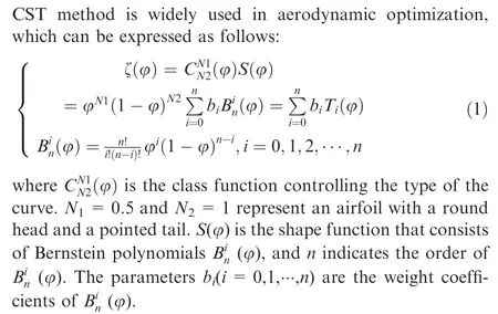
The advantage of CST method is that each reasonable parameter combination can lead to a smooth shape of the curve.28However, the CST method does not allow local modifications,and the number of parameters is limited by its inherent property. In this paper, non-uniform B-spline29curve is implemented to improve the CST method,and a new parameterization method is established, which is called non-uniform B-spline refinement CST (BCST). The main idea of BCST method is to superimpose a low-order non-uniform B-spline curve on another low-order CST curve, and the final curve is controlled by the parameters of the two component curves.The BCST curve can be expressed as follows:

where ζ(φ) represents the CST curve, R(φ) represents the Bspline curve, φ=x/c and ξ=y/c are dimensionless coordinates, and c is the length of airfoil chord. R(φ) can be expressed as follows:
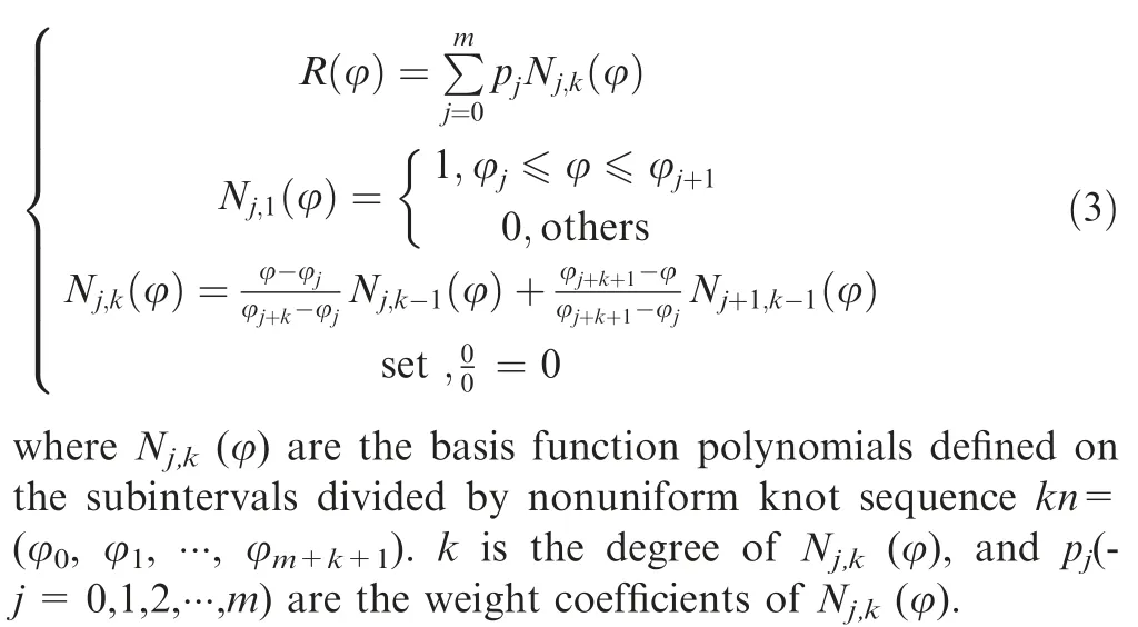
The BCST method combines the advantages of CST method and B-spline curve, which facilitates local modifications and allows more parameters without increasing the order of the curve. Therefore, it is used for the parameterization of nacelle in this paper. To describe the nacelle, its outline needs to be parameterized first.Considering the inlet flow characteristics of the engine,the inner surface of the nacelle is fixed,and the design optimization is limited to the outer surface. In this study, the nacelle is considered to be symmetrical. To control the number of parameters and avoid nacelle deformity, only the longitudinal curves at the azimuth angles of 0° and 180°are expressed as BCST curves to describe the outer surface of the nacelle.
For example, the longitudinal curve on φ=0° can be replaced by a BCST curve,which is obtained by superimposing a 4th order CST curve and a 3rd order non-uniform B-spline curve, as shown in Fig. 1. The 4th order CST curve can be regarded as the weighted sum of five components denoted by T0(φ)-T4(φ),and the 3rd order B-spline curve can be regarded as the weighted sum of four components denoted by N0,3(φ)–N3,3(φ). Therefore, the longitudinal curve on φ=0° can be controlled by nine parameters (b0-b4and p0-p3). Further, to realize local modification of the nacelle lip, the knot sequence of 3rd order B-spline curve is set as kn=[0,0,0,0.05,0.1,0.4,0.7,1].As shown in Fig.2,N0,3(φ)is defined in the interval[0,0.1], so the curve geometry in this interval can be independently changed by coefficient p0.

2.2. Aerodynamic analysis method
Here, the Reynolds-Averaged Navier-Stokes (RANS) equations are used as the governing equations for calculating the aerodynamic characteristics. The γ-Reθmodel proposed by Menter and Langtry30,31is considered as the transition model.This model combines the advantages of the Shear Stress Transport(SST) k-ω turbulence model and the γ-Reθtransition formula. Further, it incorporates two additional transport equations of the intermittent factor γ and the local-transition Reynolds number R~eθt.
The equation for γ can be used to simulate the flow in the transition region, which is expressed as follows:
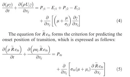
These equations are explained in the Refs. 30,31.
To verify the accuracy of the numerical calculation method for nacelle,a revolution body designed by NASA with fineness ratio of 7.5 is used as the test model32(see Fig.4).A structured H-type 3D grid is adopted in the numerical calculation (see Fig. 5). To precisely capture the transition boundary layers,y+is considered to be close to 1.33The drag coefficient and transition location of the revolution body were calculated,where the angle of attack was 0° and the Mach number (Ma)changed from 0.3 to 0.9, and the results were compared with the experiment results of Ames 12-foot pressure wind tunnel.Fig.6 shows the pressure coefficient Cpand friction coefficient Cfcontours of the revolution body under the typical state,where Ma=0.85 and Re=1.2×10⁷. Fig. 7 shows that the CFD results are in good agreement with the experimental results,which verifies the accuracy of the numerical calculation method for revolution bodies such as nacelles.
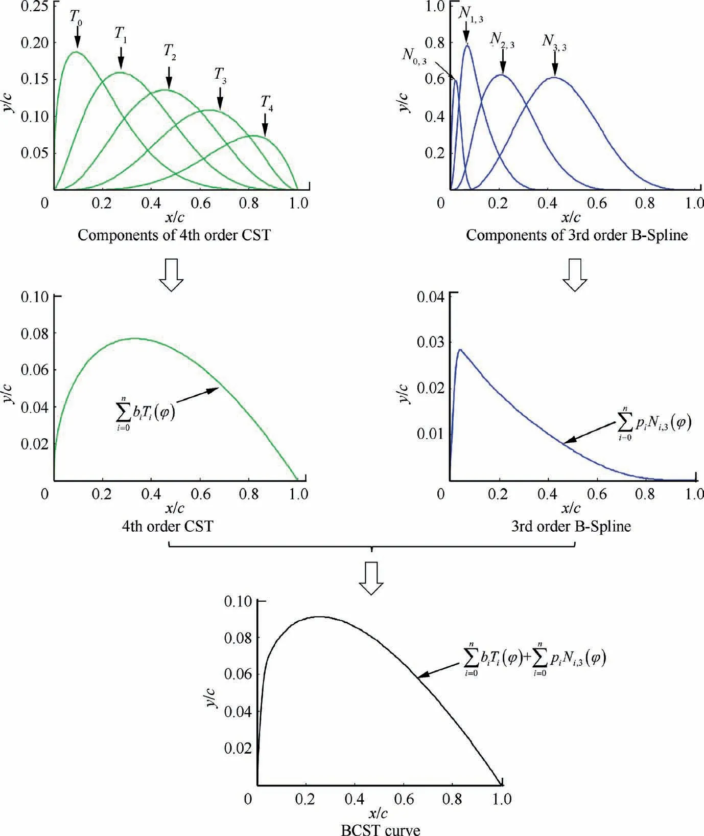
Fig. 1 Parameterization process of BCST curve.
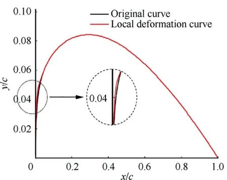
Fig. 2 Local deformation by p0 in BCST curve.
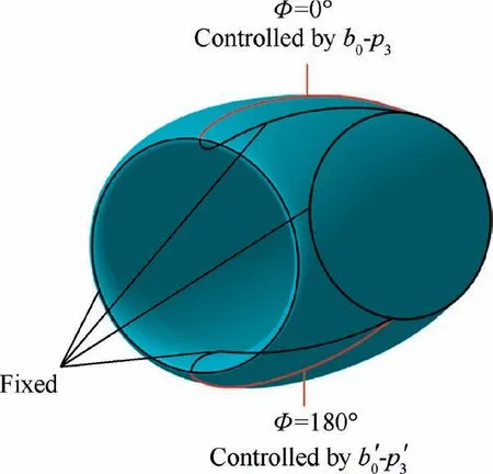
Fig. 3 Geometric modeling of the nacelle.

Fig. 4 Revolution body designed by NASA.
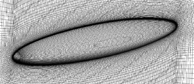
Fig. 5 Computational grid of revolution.
The grid used for the calculation of nacelle is similar to that used for the revolution body,as shown in Fig.8.The length of the nacelle is L, and the distance between the boundary of computational domain and the nacelle lip is 10L. Further, the distance from the computational domain to the trailing edge of the nacelle is 15L,and the distances from the upper and lower boundary to the center axis of the nacelle are both 10L.To test the mesh independence, five grids of the same nacelle shape with different densities are used to calculate aerodynamic characteristics when the angle of attack is 0°and the Mach number is 0.85. The information of the four grids is shown in Table 1.As shown in Fig.9,the calculation results tend to be stable as the grid density increases. The drag coefficient CDand transition location Xtrof Grid 1 and Grid 2 are very different than that of Grid 5.Therefore,Grid 1 and Grid 2 cannot be used to accurately calculate CDand Xtr.The calculation results of Grid 4 are remarkably close to those of Grid 5,while its number of cells is much less. Thus, considering the accuracy and computational cost, Grid 4 is employed for calculation.

Fig. 6 Contours of revolution body for Ma=0.85 and Re=1.2×10⁷.
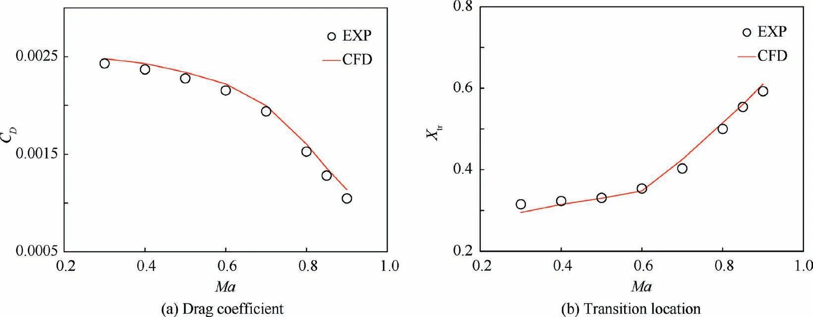
Fig. 7 Aerodynamic characteristics of the revolution for Re=1.2×10⁷.

Fig. 8 3D computational grid of nacelle.
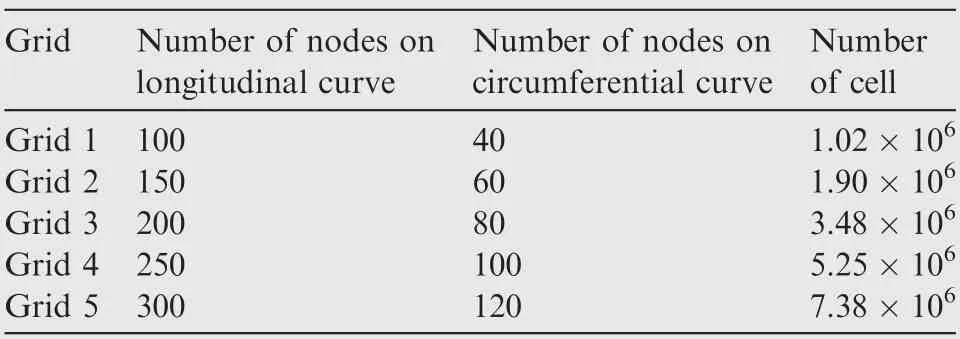
Table 1 Information of four grids.
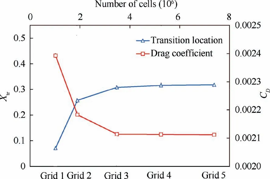
Fig. 9 Comparison of five grids.
3. Adaptive-surrogate-based robust optimization strategy
Compared to the single-point design,the robust design method can maintain a more stable performance under uncertainties,as shown in Fig. 10. In this section, the construction method of robust optimization system for NLF nacelle is explained.
3.1. Robust optimization model
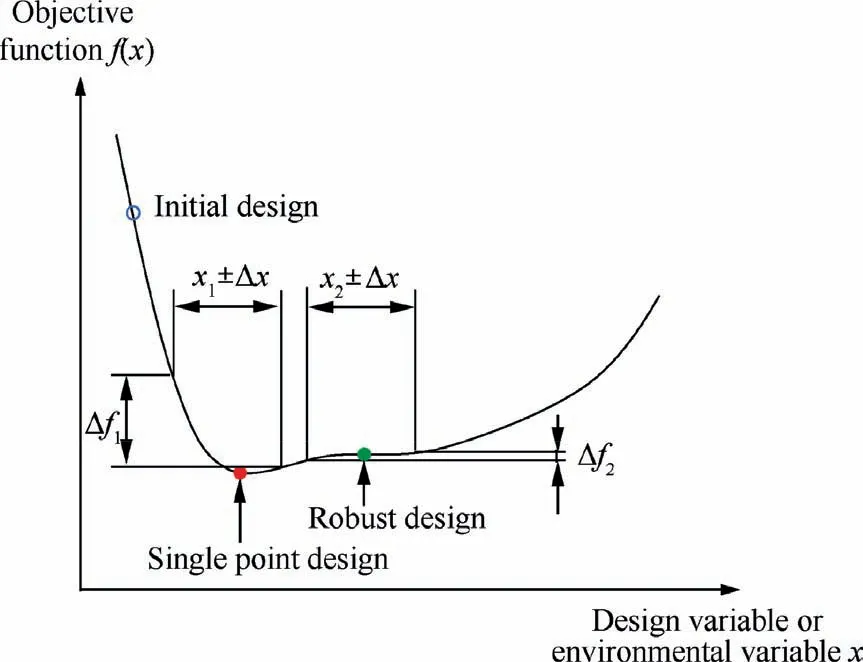
Fig. 10 Robust design and single-point design.
The nacelle needs to provide sufficient space to accommodate some engine subsystems, so the internal volume of nacelle should be a constraint variable in the optimization process.The surface area has a direct effect on the frictional resistance of the nacelle.The relationship between the outer surface area and the nacelle volume can be described by volume ratio,which is defined as the ratio of the nacelle volume to the sphere volume that has the same area as the outer surface.34The volume ratio should be large enough to guarantee a small area of outer surface in the optimization process, so the volume ratio of the nacelle is also adopted as a constraint variable.The volume ratio (η) can be calculated as

where V is the nacelle volume, and Soutsideis the area of nacelle’s outer surface.
Generally, the optimization of NLF nacelle aims at realizing a large laminar flow range and minimum aerodynamic drag under cruise condition,which is called single-point design optimization or deterministic optimization. In the deterministic optimization of NLF nacelle,although the economy is only related to the drag coefficient, the laminar area ratio is also used as one of the objective functions to examine the general principle of such a design. Therefore, the deterministic optimization model can be described as follows:

where x is vector form of the optimization variables, Vminis the minimum volume of the nacelle, ηminis the minimum volume ratio of the nacelle,and λ is the laminar area ratio on the outer surface, which can be calculated by
The 2D space formed by the random variables Ma and a is called the disturbance space. In contrast to deterministic optimization,the robust optimization focuses on the average value and stability of the aerodynamic performance in the disturbance space. Therefore, the mean drag coefficient and the mean laminar area ratio are used as the objective functions of the robust optimization. In addition, to consider the sensitivity of the aerodynamic performance to environmental disturbance, the variances of the drag coefficient and laminar area ratio are used as the aerodynamic constraints in the robust optimization model. Further,the geometric constraints in the robust optimization are the same as those in deterministic optimization.Then,the robust optimization model of NLF nacelle can be described as
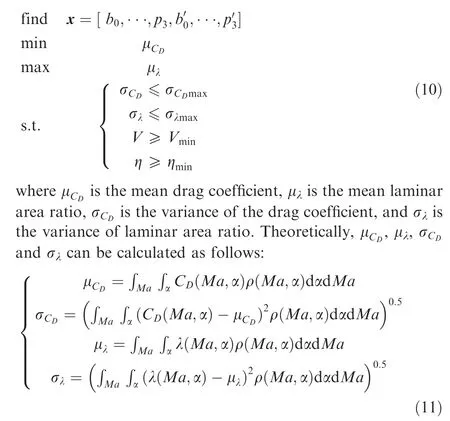
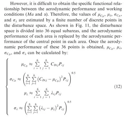
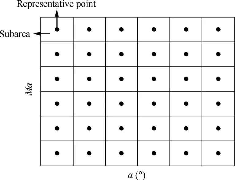
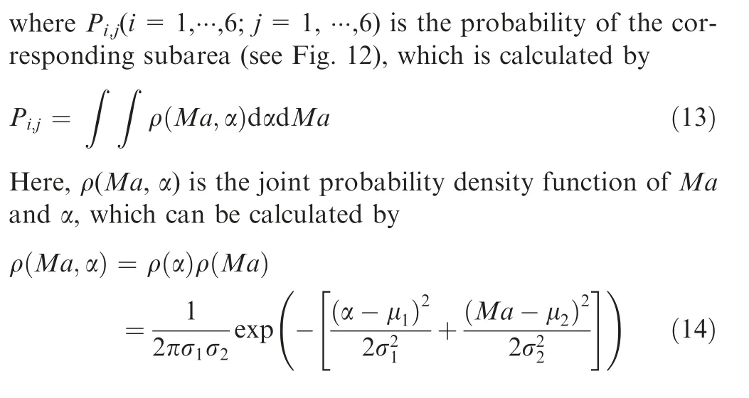
Fig. 11 Division of disturbance space and representative points of each subarea.
3.2. Adaptive-surrogate-based optimization method
The optimization strategy in which surrogate model is applied to predict the output response is called surrogate-based optimization, which can significantly improve the prediction efficiency.35,36Since different kinds of surrogate models are suitable for different optimization problems,selecting an appropriate surrogate model for specific problem is important in surrogate-based optimization.To this end,the prediction accuracies of three commonly used surrogate models(kriging model,response surface model,and Back Propagation(BP)neural network model)for the aerodynamic characteristics of NLF nacelle are compared,which are obtained by training on the same dataset for unknown samples.Fig.13 shows that the BP neural network has higher accuracy than the other models for this problem,so it is adopted in the optimization system.
Fig. 14 shows the structure of the BP neural network model, where I1-Inare the input variables in the input layer,namely geometry parameters, and O1-Olare the output variables in the output layer, namely aerodynamic response parameters.
In surrogate-based optimization, another crucial technique is the detailed optimization strategy, which can greatly affect the efficiency and accuracy of the optimization process. The traditional optimization strategy based on static surrogate model is not only inefficient but also causes large error near the optimal solution, leading to a poor optimal design. Moreover,it is difficult to provide an appropriate design space at the beginning when the design variables are obtained using a parametric method without clear geometric meaning (such as CST method). Since the design space is usually fixed in the traditional optimization method, an inappropriate design space may cause the optimal solutions to appear at the boundary of the design space and deviate from the real optimal solution.It can also lead to useless computational cost because of a huge design space.Therefore,it is more reasonable to flexibly adjust the design space and update the surrogate model according to the actual situation in the optimization process,which can provide an optimal design with higher success probability and efficiency.
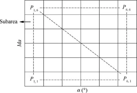
Fig. 12 Probabilities of subareas.
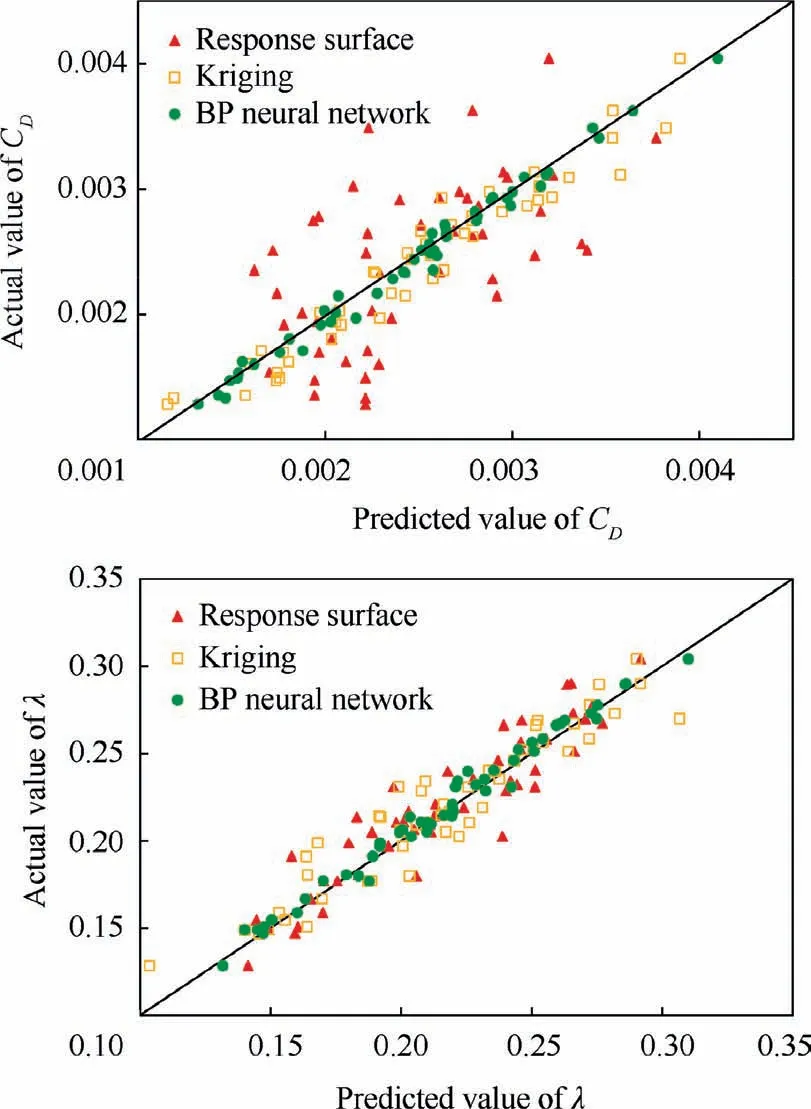
Fig. 13 Comparison between the predicted values by different surrogate models and actual values by CFD.
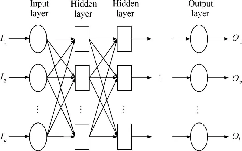
Fig. 14 Structure of BP neural network.
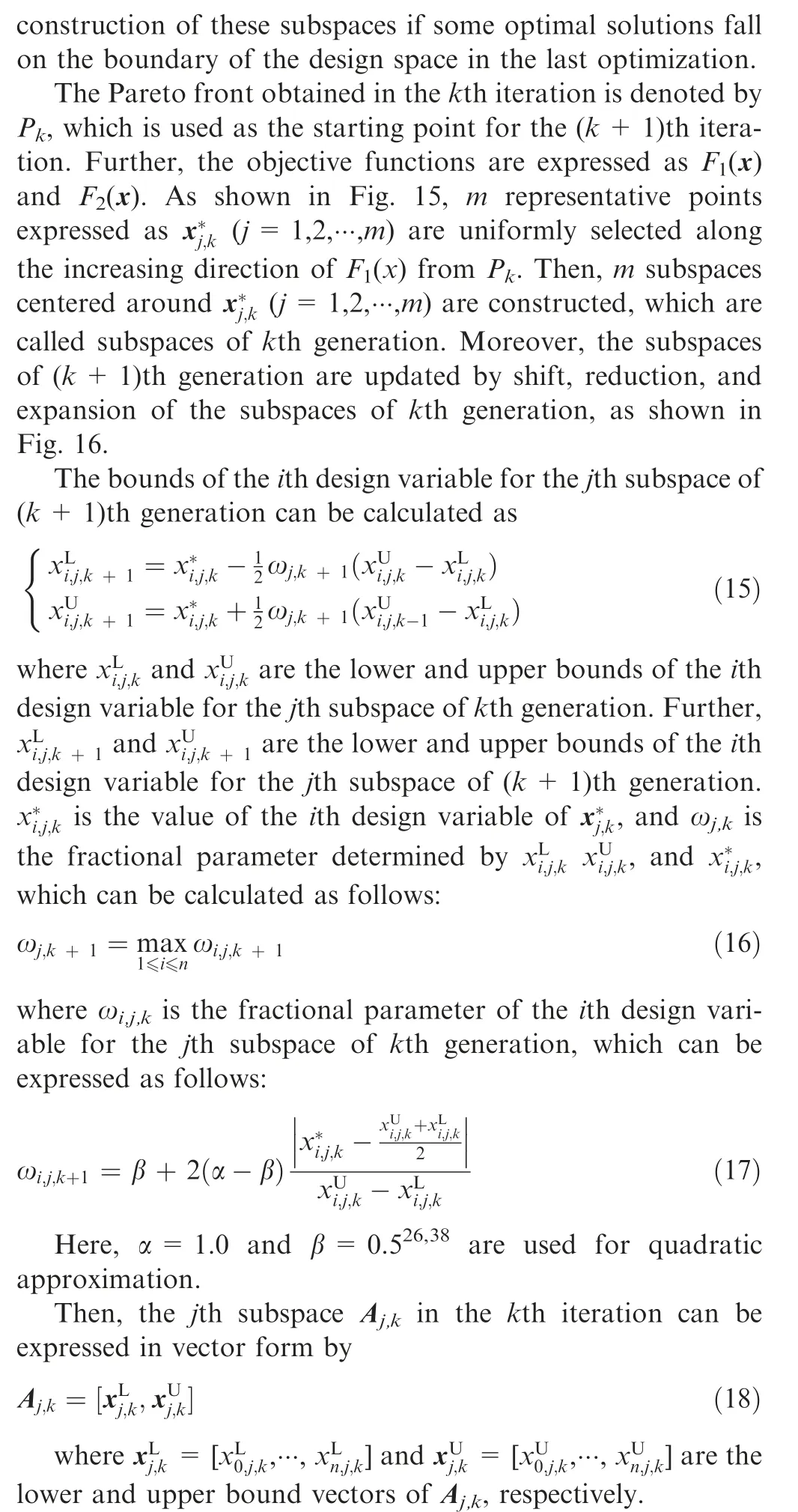
Therefore, once the optimal solution falls on the boundary in the iterative process,the design space can be adjusted in the next iteration through shift and expansion operation to avoid missing the real optimal solutions. At the same time, since the subspaces are roughly reducing continually, the efficiency of surrogate model reconstruction can be improved.
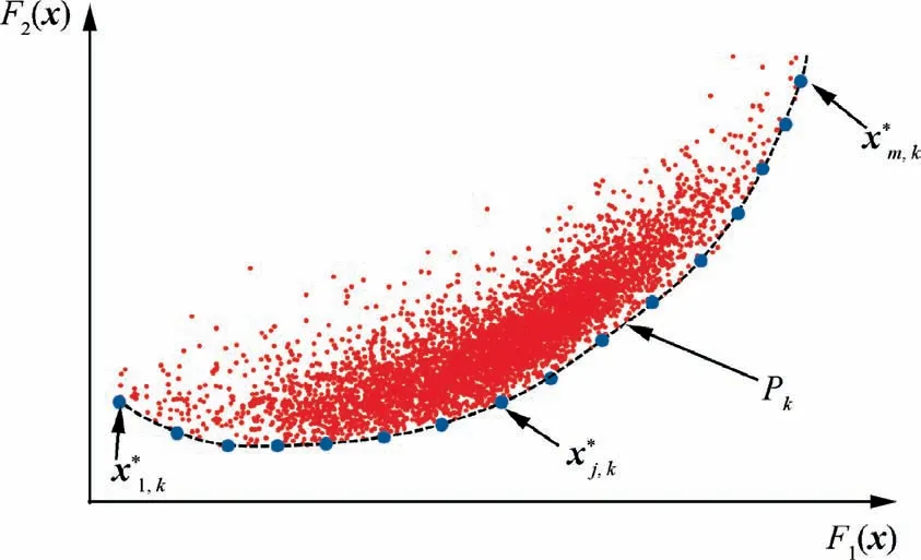
Fig. 15 Representative points on Pareto front.

Fig. 16 Updating subspaces for the reconstruction of surrogate model.
Since this optimization strategy is an iterative procedure,the iteration must be terminated by given criteria. To guarantee the local accuracy of the surrogate model in the important region and obtain a Pareto front close enough to the real Pareto front within a limited number of iterations, following two convergence criteria are adopted in the optimization process.
(1) The maximum errors of approximate objective values predicted by BP neural network must be lower than the given tolerances, which can be expressed as
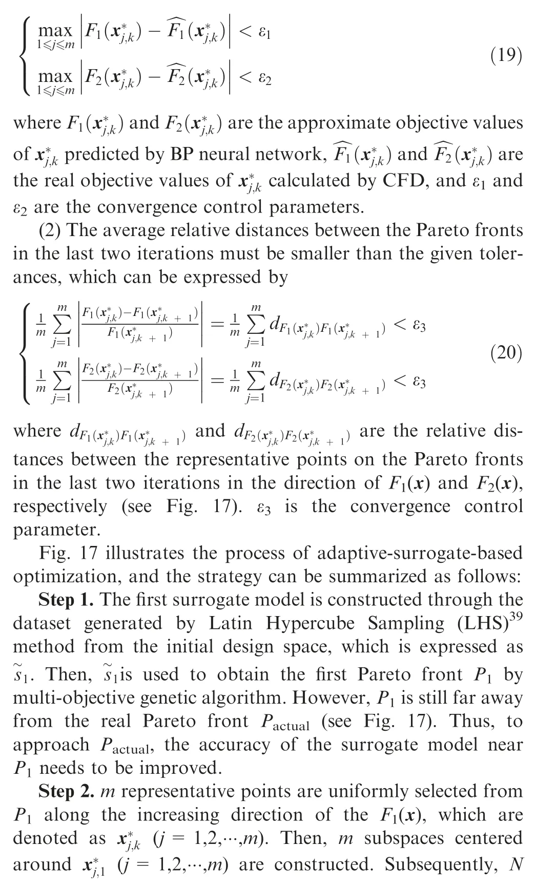
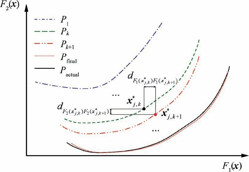
Fig. 17 Process of adaptive-surrogate-based optimization.


Step 4.Steps 2 and 3 are repeated until the convergence criteria described by Eqs. (19)–(20) are satisfied. Then, the final Pareto front Pfinalcan be obtained, which is sufficiently close to the real Pareto front Pactual.
3.3. Optimization procedure
To obtain a feasible design for implementing robust optimization, the nacelle needs to be first optimized deterministically.Thus, the ASBRO strategy is established in this subsection by coupling the deterministic optimization and robust optimization models with the adaptive-surrogate-based optimization strategy. The procedure of ASBRO strategy for NLF nacelle is described as follows:
Step 1. Initialize the design space.
The geometric parameters are used as the optimization variables, and the initial design space is established according to the parameter values of the initial nacelle.
Step 2. Establish initial BP neural network model.
The sampling space is divided into a design space composed of 18 optimization variables and a state space composed of Ma and a. LHS is used to generate 50 combinations of optimization variables from the design space,which represent 50 nacelle shapes. Further, 6 combinations of Ma and a are randomly generated for each nacelle shape from the state space, which represent 6 working states. The working states of each nacelle shape are calculated by CFD method to obtain the dataset for surrogate model construction. In fact, for each nacelle shape,after calculating the first working state, the other working states can be calculated rapidly since the grid and convergence solution have been obtained. Then, the initial BP neural network model is built by the dataset, which can be used to simulate the functional relationship between the drag coefficient,laminar area ratio, and input variables.
Step 3. Execute deterministic optimization.
Based on the initial BP neural network model, the deterministic optimization of NLF nacelle described in Eq. (7) is completed, and first Pareto front is obtained.
Step 4.Reconstruct the BP neural network of deterministic optimization.
The BP neural network needs to be reconstructed to improve the precision of prediction.m subspaces are constructed around m representative points selected from the previous Pareto front.Then, the neural network is updated by adding 50 additional samples from these subspaces.Further,the optimization process is repeated to obtain a new Pareto front by the new neural network. If the maximum error of approximate objective values predicted by the new neural network is less than ε1and ε2and the relative distance of the last two Pareto fronts is smaller than ε3,the next step is executed,and the latest Pareto front is considered as the optimal solution of deterministic optimization.Otherwise,Step 3 is repeated.
Step 5. Execute robust optimization.
Based on the optimization results of deterministic optimization, the robust optimization described in Eq. (10) is performed, and first Pareto front is obtained.
Step 6. Reconstruct the BP neural network of robust optimization.
The neural network is updated using the same operation as describedinStep4.Then,thenewneuralnetworkisusedtoagain perform robust optimization for obtaining a new Pareto front.
Step 7. Obtain the robust optimal solution.
Step 6 is repeated until all the convergence criteria of robust optimization are satisfied. Then, the almost real Pareto front can be obtained.
The optimization procedure is summarized in Fig. 18.
4. Case study and analysis
To validate the feasibility and effectiveness of ASBRO strategy for NLF nacelle, the nacelle of NASA Common Research Model was used as the study object. This nacelle with nonaxisymmetric geometry works under typical transonic cruise condition(see Table 2)and is designed for full turbulence flow.Therefore, the optimization methods as well as the basic laws obtained in this case can be used as a reference for designing NLF nacelle.
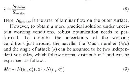
To describe the uncertainty of the working conditions around the nacelle, the Mach number and the angle of attack are assumed to follow normal distribution and can be expressed as follows:

For the convenience of description,the initial nacelle shape of NASA Common Research Model is denoted by Initial in the following subsections.Further,to simplify the calculations,the nacelle in this study is designed without considering the power.
4.1. Optimization results
Before robust optimization, the nacelle was first optimized deterministically to obtain a feasible design. Five iterations of optimization and 1500 CFD calculations of samples were performed in the deterministic optimization. Fig. 19(a) shows an overview of the computed solutions in the deterministic optimization process, and Fig. 19(b) shows the Pareto front extracted from the available computed solutions. Considering economic benefit, the solution with the smallest total drag coefficient is selected as the optimal solution of deterministic optimization, which is called Dopt (see Fig. 19(b)). As shown in Table 3,compared to Initial,the laminar area ratio of Dopt increases to 19.4% from 4.5%, and the drag coefficient of nacelle decreases by 1.86 counts (the reference area for drag calculation is the wing area of NASA Common Research Model).
Then, based on the results of deterministic optimization,additional two iterations of optimization and 600 CFD calculations of samples were performed to complete the robust optimization.Finally,a total of 2100 CFD calculations of samples were implemented in seven iterations of optimization to establish a reliable surrogate model for the robust optimization.The average prediction error of the last surrogate model is shown in Fig. 20.
The deviations (with respect to CFD response) of the optimal solutions on the Pareto front obtained using the ASBRO and traditional optimization method with the same number of samples are compared in Fig. 21.Compared to the traditional optimization method, the ASBRO strategy significantly improves the efficiency and accuracy of optimization and reduces the calculations by nearly 60% with the same deviation of the optimal solutions. Since the surrogate model is updated by adding points centered on the Pareto front obtained from the previous optimization in ASBRO strategy,the prediction errors of the objective values near the Pareto front can be reduced rapidly. In addition, by considering the average relative distances of the Pareto fronts in the last two iterations as the convergence condition, the optimized Pareto front can finally converge to the real Pareto front with several iterations. However, in the traditional optimization strategy,the surrogate model is usually updated by aimlessly adding points in the entire design space, which cannot improve the accuracy of the area near the Pareto front, leading to a lower efficiency.
Fig. 22(a) shows an overview of the computed solutions in the robust optimization,and Fig.22(b)shows the Pareto front extracted from the available computed solutions.The distribution of Pareto front shows that the average drag coefficient initially decreases and then increases with the increase in the average laminar area ratio. Initially, the frictional drag decreases with the increase in the laminar area ratio, which leads to a slight decrease in the total drag. Subsequently, the reduction in the frictional drag is not sufficient to offset the sharp increase in the pressure drag, causing a significant increase in the total drag. Further, the Pareto front of deterministic optimization has similar characteristics. Considering economic benefit, the solution with the smallest mean total drag coefficient is selected as the optimal solution of robust optimization, which is called Ropt (see Fig. 22(b)). Compared to Initial, Ropt attains a benefit of 1.98 counts in the average drag coefficient and increases the average laminar area ratio to 21.6% (see Table 4).
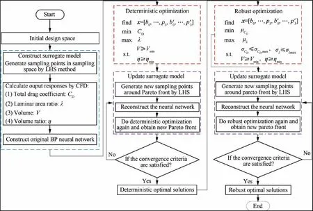
Fig. 18 Flowchart for robust optimization of NLF nacelle.
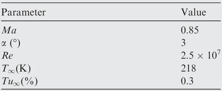
Table 2 Parameters of cruise conditions.
4.2. Sensitivity analysis
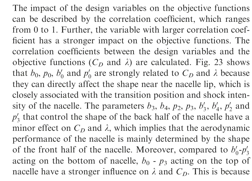
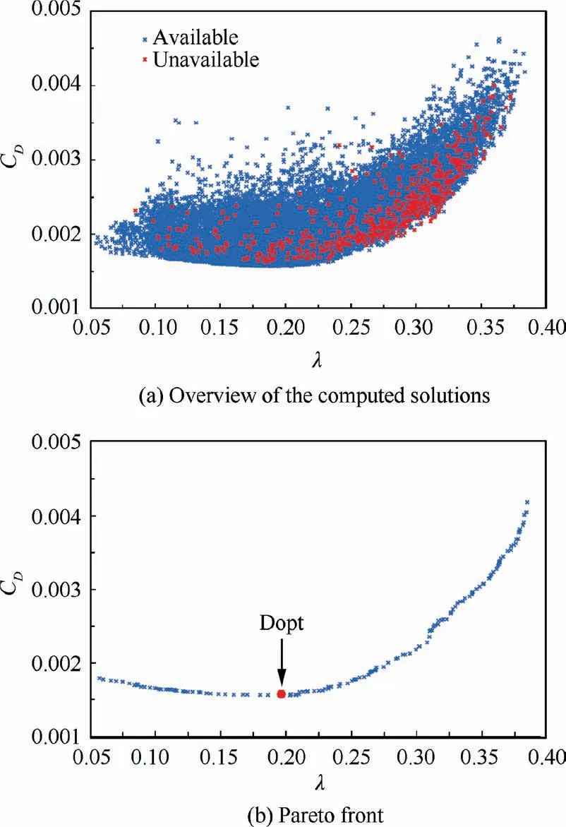
Fig. 19 Results of deterministic optimization.


Table 3 Comparison between Initial and Dopt.
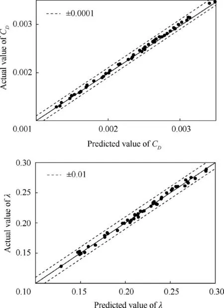
Fig. 20 Comparison between predicted values by the last surrogate model and actual values by CFD.
4.3. Aerodynamic analysis on cruise conditions
In this subsection, the aerodynamic characteristics of the nacelle before and after optimization under the cruise condition are examined. Fig. 24 compares the pressure drag coefficient (CDp), friction drag coefficient (CDf), and total drag coefficient (CD-total) of Initial, Dopt, and Ropt at the cruise condition.It is clear that CDpof Dopt and Ropt is slightly larger than that of Initial,but CDfof Dopt and Ropt is lower than that of Initial by 23% and 24%, respectively. Therefore, the decrease in the total drag of Dopt and Ropt can be attributed to the decrease in the friction drag. On the one hand, the surface areas of Dopt and Ropt decrease due to the increase in the volume ratio(see Table 4).On the other hand,the laminar area of Dopt and Ropt obviously increases after optimization.Moreover,it is noteworthy that the aerodynamic characteristic of Dopt is slightly better than that of Ropt at the cruise conditions.
Fig. 25 compares the shape changes of Initial, Dopt, and Ropt at different azimuth angles, and Fig. 26 shows the pressure coefficient(Cp)distributions of the three nacelles at different azimuth angles under the cruise conditions. Fig. 27 shows the pressure coefficient and friction coefficient(Cf)contours of Initial, Dopt, and Ropt, respectively. Since the friction drag coefficient in the turbulent flow area is much larger than that in the laminar flow area, the position where the friction drag coefficient suddenly increases is the starting position of transition,and the blue area before the transition position is the laminar flow area.
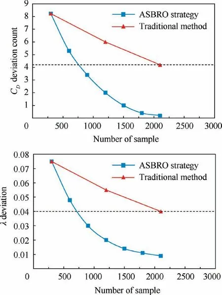
Fig. 21 Deviation of objective function near Pareto front.
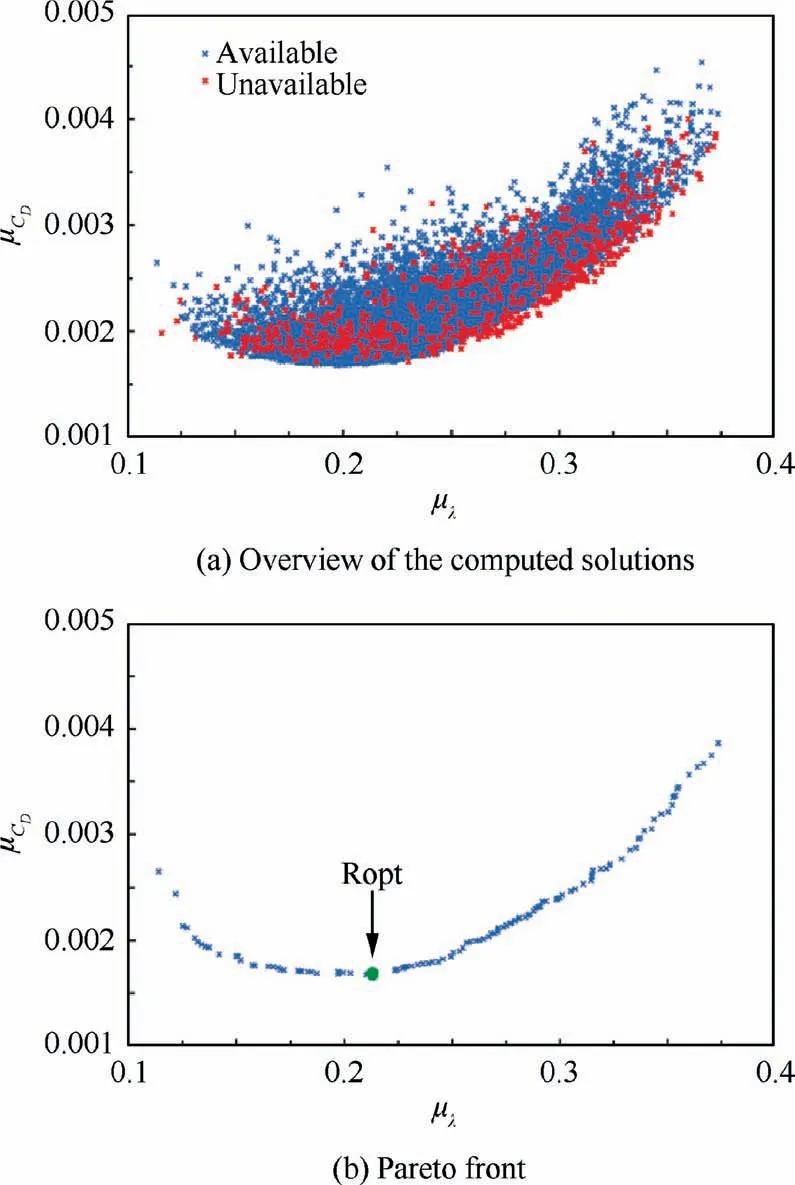
Fig. 22 Results of robust optimization.

Table 4 Comparison between Initial and Ropt.
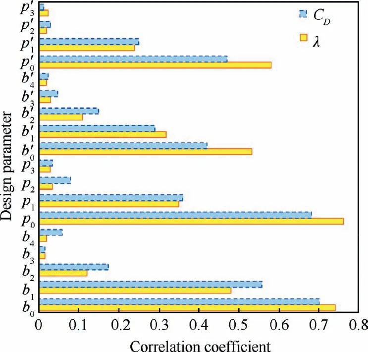
Fig. 23 Correlation coefficients between design variables and objective functions.
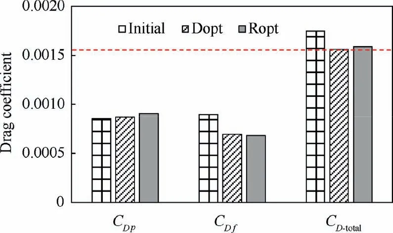
Fig. 24 Drag coefficient of three nacelle shapes at cruise conditions.
As shown in Fig.26,there are strong suction peaks near the front edge of Initial, which causes the flow to enter the unfavorable pressure gradient and triggers transition prematurely.Then,only 4.5%laminar area is obtained on the outer surface of Initial(see Fig.27(a)).In contrast,both Dopt and Ropt can maintain a long favorable pressure gradient region on the front half due to the larger radius of nacelle lip, which extends the laminar area of Dopt and Ropt significantly. Therefore, the blunt leading edges can help nacelle to maintain a favorable pressure gradient region and increase the laminar flow area.Moreover, the laminar flow can also be maintained for a certain distance even under a weak unfavorable pressure gradient(see Fig. 26(a) and Fig. 27(b)).
4.4. Aerodynamic analysis under uncertain working conditions
A well-designed nacelle should exhibit good aerodynamic performance at the cruise conditions,and it must be able to maintain stable aerodynamic characteristics when Ma and a fluctuate randomly. To further investigate the influence of working conditions on the aerodynamic characteristics of the three nacelles, CFD solver was used to simulate their aerodynamic performances at different Ma and a.
Fig. 28 shows the average pressure drag coefficient (μCDp),average frictional drag coefficient (μCDf), and average total drag coefficient (μCDtotal) of Initial, Dopt, and Ropt in the disturbance space.Compared to Initial,μCDtotalof Dopt and Ropt reduce significantly, which is mainly due to the reduction of μCDf. Further, Ropt has a smaller μCDtotalthan Dopt in the disturbance space (see Fig. 28), though Dopt has a lower resistance than Ropt at the cruise conditions (see Fig. 24).
Fig. 29 shows the variation in CDand λ of Initial, Dopt,and Ropt as a function of Ma (0.82–0.88) when a=3°. It is evident in Fig. 29(a) that Ropt avoids the rapid change in CDand can retain low drag characteristic in the entire Ma range.Especially,CDof Ropt is much smaller than that of Initial and Dopt when Ma is higher than 0.85.Further,λ of Ropt is hardly affected by Ma,as shown in Fig.29(b).Fig.30 shows the variation in CDand λ of Initial,Dopt and Ropt as a function of a (0°- 6°) when Ma=0.85. It is clear from Fig. 30(a)that Ropt has a lower CDthan Initial and Dopt when a is lower than 2.5° and higher than 3.5°. Further, λ of Ropt is higher and it changes more smoothly than that of Initial and Dopt, as shown in Fig. 30(b).
Fig. 31 and Fig. 32 show CDand λ of the three nacelles in the disturbance space,which can be used to examine the stability of nacelles. It is clear from these figures that compared to Initial and Dopt, Ropt has a wider range of low drag coefficient and higher laminar area ratio in the disturbance space.Therefore,Ropt has a better aerodynamic robustness than Initial and Dopt.

Fig. 25 Shapes of Initial, Dopt, and Ropt for different azimuth angles.

Fig. 26 Cp distributions of Initial, Dopt, and Ropt for different azimuth angles.
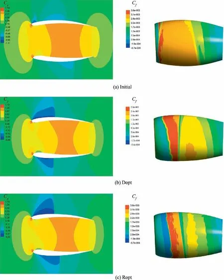
Fig. 27 Pressure coefficient and friction coefficient contours of Initial, Dopt, and Ropt.
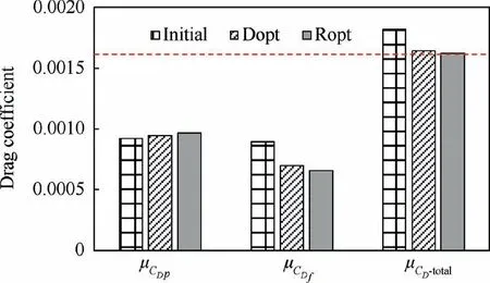
Fig. 28 Average drag coefficient of three nacelle shapes under uncertain working conditions.
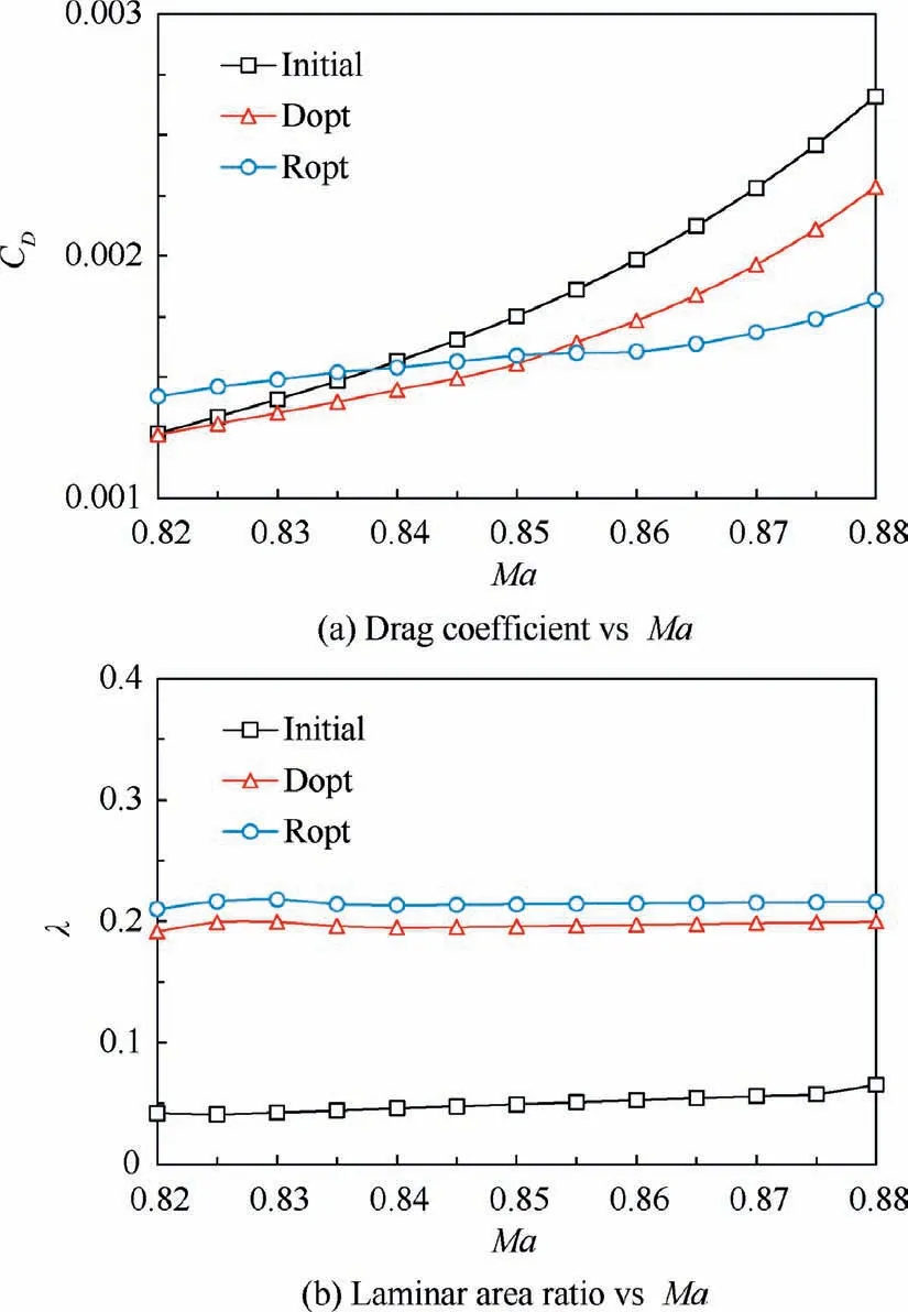
Fig. 29 Aerodynamic performance vs Mach number for three nacelle shapes (a=3°).
Based on the shape characteristics of optimized nacelles,the three main factors that influence the robustness of design results can be obtained.Firstly,an optimal lip radius is pivotal for the robustness of NLF nacelle. A small lip radius can lead to a pressure peak at the front part of the nacelle and cause a sharp shock wave. The pressure peak can be significantly affected by the angle of attack because of the small lip radius.The peak pressure coefficient on the upper nacelle may increase rapidly with the increase in the angle of attack, while that on the lower nacelle can decrease, leading to a significant variation in the laminar flow area and nacelle drag. In addition, although a large lip radius can provide a gentle pressure distribution, it may also cause a rapid increase in the pressure drag as the Mach number increases due to the huge windward area. Therefore, a moderate lip radius, which can facilitate a gentle variation of pressure coefficient at the front part of the nacelle and maintain the stability of the laminar flow, is conducive to the robustness of the NLF nacelle. Secondly,the maximum diameter has a significant impact on the robustness of the nacelle.A large maximum diameter can ensure high strength of the favorable pressure gradient,which is conducive for maintaining the stability of the laminar flow under the variation in angle of attack and Mach number. However, it can also cause a higher maximum air velocity and a powerful shock wave.As the Mach number increases,the velocity of airflow near the position of maximum diameter quickly approaches drag-divergence Mach number of the nacelle,leading to a sharp increase in the nacelle drag.Therefore,the maximum diameter should be neither too large nor too small.Thirdly,the position of maximum diameter of the nacelle also has a considerable influence on the robustness of NLF nacelle.With an appropriate lip radius, a long distance between the maximum diameter position and lip can facilitate a large favorable pressure gradient region, which can help in maintaining the stability of laminar flow when Mach number and angle of attack change. However, if the position of the maximum diameter is too far from the lip and too close to the trailing edge, the airflow may expand and rapidly accelerate after passing through the position of maximum diameter,generating a strong shock wave.Then,the drag-divergence Mach number of the nacelle can be reached with a slight increase in the flight Mach number.Thus,there is an optimal position of maximum diameter to ensure the aerodynamic robustness of the NLF nacelle.
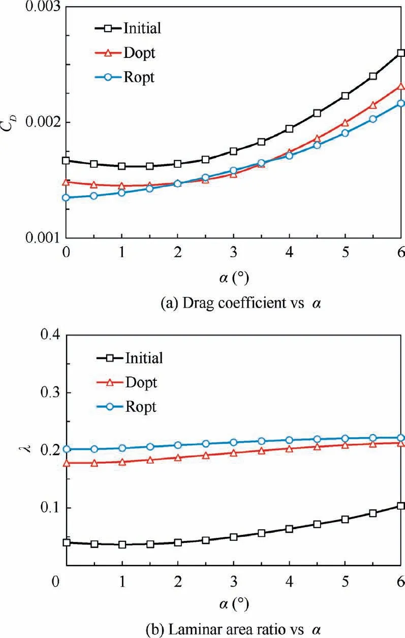
Fig. 30 Aerodynamic performance vs angle of attack for three nacelles shapes (Ma=0.85).
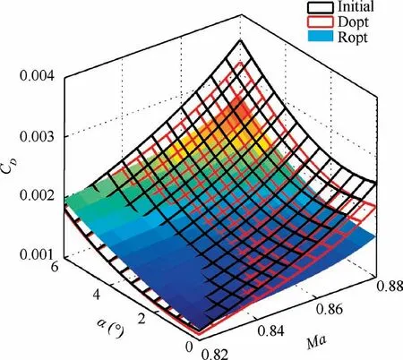
Fig. 31 CD response surfaces of three nacelle shapes.
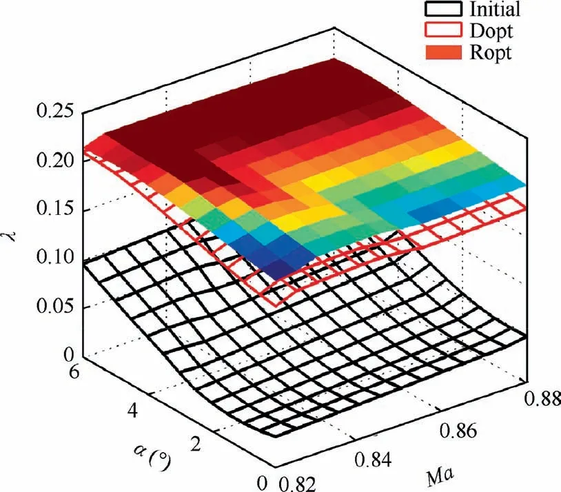
Fig. 32 λ response surfaces of three nacelle shapes.
5. Conclusions
In this study, an effective strategy called ASBRO was proposed to improve the aerodynamic robustness of NLF nacelle under uncertain working conditions. The feasibility and effectiveness of this strategy for NLF nacelle were examined by a case study. The aerodynamic characteristics of the optimized nacelles were analyzed in detail by numerical simulations,and the main results of this analysis can be summarized as follows:
(1) Compared to the traditional optimization method, the application of ASBRO strategy in the NLF nacelle significantly improved the design efficiency and reduced the calculation amount by nearly 60% with the same deviation of the optimal solutions.
(2) The optimization strategy changed the pressure distribution and volume ratio of the nacelle by facilitating larger radius of nacelle lip and smaller maximum diameter.Further, it expanded the favorable pressure gradient region. Thus, the transition on the nacelle was delayed and the surface area was reduced.
(3) As the required laminar area ratio increased, the minimum drag coefficient of the nacelle tended to decrease first and then increase. An appropriate laminar area ratio reduced the total drag of the nacelle, but a large laminar area ratio always led to a huge pressure drag,which increased the total drag.
(4) The favorable pressure gradient over the outer surface of nacelle could help in delaying the transition, but the laminar flow could be maintained for a short distance under a weak unfavorable pressure gradient.
(5) After the robust optimization, a benefit of 1.98 counts was attained in the average drag coefficient, and the average laminar area ratio increased from 5.6% (initial nacelle) to 21.6%. Although deterministic optimization facilitated a better performance of the nacelle under the cruise conditions, the nacelle obtained through robust optimization exhibited lower average drag and wider range of low drag coefficient, and it maintained a stable and high laminar area ratio in the disturbance space.
(6) The aerodynamic robustness of the NLF nacelle was observed to be mainly determined by the parameters affecting the shape of the front half of the nacelle,including lip radius, maximum diameter of nacelle, and location of the maximum diameter. The lip radius and maximum diameter of the nacelle obtained through robust optimization were slightly larger than those based on deterministic optimization, and the location of the maximum diameter for the robust result was further backward.
Overall,this study presented a facile strategy for the robust optimization of NLF nacelle under uncertain working conditions. However, the effects of engine power and wing interference were not considered here. In future, we will incorporate more influencing factors to establish a more realistic robust optimization system for NLF nacelle.
Declaration of Competing Interest
The authors declare that they have no known competing financial interests or personal relationships that could have appeared to influence the work reported in this paper.
Acknowledgement
This study was financially supported by the Commercial Aircraft Corporation of China Ltd.
 CHINESE JOURNAL OF AERONAUTICS2021年10期
- CHINESE JOURNAL OF AERONAUTICS的其它文章
- Direct dynamic-simulation approach to trajectory optimization
- A strong robustness open-circuit fault diagnosis strategy for novel fault-tolerant electric drive system based on d-q-axis current signal
- Nonlinear vibration response characteristics of a dual-rotor-bearing system with squeeze film damper
- Ground maneuver for front-wheel drive aircraft via deep reinforcement learning
- Numerical simulation of a UAV impacting engine fan blades
- Recent advances in precision measurement &pointing control of spacecraft
