Aerodynamic design of tractor propeller for high-performance distributed electric propulsion aircraft
Kelei WANG, Zhou ZHOU, Zhongyun FAN, Jiahao GUO
School of Aeronautics, Northwestern Polytechnical University, Xi’an 710072, China
KEYWORDS Aerodynamic loading distributions;Aerodynamic performance;Distributed electric propulsion;Hybrid design framework;Propeller/wing integration;Variable-fidelity propeller modelling and aerodynamic analyses methods
Abstract Aiming to maximize the aerodynamic performance of the Distributed Electric Propulsion (DEP) aircraft, a hybrid design framework which focuses on the aerodynamic performance of the propeller/wing integration has been developed and validated numerically. Variable-fidelity modelling for propeller aerodynamics has been used to achieve computational efficiency with reasonable accuracy. By optimizing the aerodynamic loading distributions on the tractor propeller disk,the induced slipstream is redistributed into a form that is beneficial for the wing downstream,based on which the propeller blade geometry is generated through a rapid inversed design procedure.As compared with the Minimum Induced Loss(MIL)propeller at a specified thrust level,significant improvements of both the lift-to-drag ratio of the wing and the propeller/wing integrated aerodynamic efficiency is achieved, which shows great promise to deliver aerodynamic benefits for the wing within the propeller slipstream without any additional devices.
1. Introduction
Due to the rising costs of fossil fuels and growing environmental concerns over the past several years, increased interest in the development of both fully electric and hybrid electric vehicles has been expressed by some research institutes and companies, as seen in NASA Maxwell X-57,1Airbus E-Fan2and Pipistrel Alpha Electro.3Witfhin this context, much work has been undertaken to find technologies which can exert the greatest degree of electric motor use function. Configurations based on the Distributed Electric Propulsion (DEP) concept are commonly considered capable of yielding a net benefit in total efficiency due to synergistic airframe-propulsive coupling.4Despite the currently existing bottlenecks in battery technologies and megawatt (MG) generator technologies, the DEP aircraft are widely seen as stepping-stone platforms for entrance into more powerful, high-performance vehicles.5
Taking the X-57 DEP aircraft as an example, there are totally 12 smaller tractor propellers being distributed upstream of the wing Leading Edge (LE), which lead to notable lift augmentation by increasing the dynamic pressure and circulation experience by the downstream wing at low-speed conditions.In return,the presence of the wing acts as a sort of stator vane which tends to reduce the effective swirl of the downstream flow and further results in an effective increase in both propeller efficiency and wing induced drag.6As illustrated by a demonstration wing tested on the Hybrid-Electric Integrated Systems Testbed (HEIST) truck at NASA Armstrong Flight Research Center (AFRC), a lift augmentation of nearly 240% was achieved at both takeoff and landing power for the blown-wing configuration compared with the clean wing.7–8It seems that the X-57 DEP configuration enables the use of smaller wings for greater high-speed cruise efficiency without compromising its low-speed performance due to the high-lift capability, and it also entails advantageous solutions for stability and control because the distributed propellers can be regarded as control devices.Hence the distributed smaller propellers can be decoupled from the high-speed cruise thrust generation and installed solely to augment lift at lowspeed conditions, which act collectively as a form of conventional high-lift devices for the wing and have therefore been termed high-lift propellers.5,9–12This is quite different from the traditional propeller concept which aims to achieve maximum propulsive efficiency based on considerations of classical metrics such as Minimum Induced Loss (MIL).13–17Thus, the high-lift propellers are no longer designed in traditional ways because the purpose of high-lift propellers differs from traditional ones.Recently,the research by Patterson et al.11,12indicates that the near-uniform axial velocity profiles induced by the propeller can lead to the most effective influences on the wing downstream,which means that the induced velocity profiles can be considered as objects to carry out the aerodynamic design of high-lift propellers. Consequently, a rapid high-lift propeller design method based on Blade Element Momentum Theory (BEMT) and thin wing theory has been developed and studied in both numerical and experimental ways.18,19However, the use of low-fidelity analysis methods makes it only suitable for the early-phase design of the high-lift propeller as the detailed analyses of the turbulence development in the slipstream is not possible. Low-fidelity modelling is not enough for the complete assessment of the aerodynamic performance. Besides, the high-lift propeller concept focuses on the lift benefits with the primary purpose of improving the low-speed performance of X-57 DEP aircraft, but when it comes to the other kinds of DEP aircraft, such as the Helios20which operates at low-speed conditions, the primary purpose of the aerodynamic design will be transformed into improving the propeller/wing integrated performance, which aims at not just high lift,but also low drag and high propulsive efficiency. In other words, with the rapid development of the DEP aircraft with strong complicated interference between the tractor propellers and the wing,both the propeller component and the propulsion system should not be designed with the purpose of optimal local performance, and instead, they should be designed with the aim of achieving total high performance of the DEP aircraft. Hence, it is necessary to carry out more detailed and extensive investigations on the aerodynamic design of tractor propellers for high-performance DEP aircraft. This is the topic of the present work.
To address the issues described above,this paper develops a hybrid design framework based on variable-fidelity aerodynamic analysis methods, in which the propeller induced slipstream characteristics can be optimized and redistributed through a high-fidelity propeller disk loading design approach,and then the propeller blade geometry can be rapidly generated based on target loading distributions. As the MIL propeller taken as the initial object, a set of tractor propellers are designed under prescribed constraints with the propeller/wing integrated performance taken as evaluation criteria.Both aerodynamic performance and flow characteristics of the designed propeller/wing integrations are discussed in details,based on which the reliability of the tractor propeller design strategy developed for high-performance DEP aircraft is studied and validated.
2. Variable-fidelity aerodynamic analysis methods
Aerodynamic analysis methods including blade element theory,21BEMT,22,23and Computational Fluid Dynamics(CFD) are well-established and have been used extensively in propeller design. In this paper, the commercially available CFD package Fluent version 19.2.0 is used to quasi-steadily simulate the complicated flow around the propeller/wing integration, and the full three-dimensional Reynolds Averaged Navier-Stokes (RANS) governing equations are solved, which are coupled with the k-ω Shear Stress Transport (SST) turbulence model.24To achieve accurate estimation of the propeller rotational behavior, the Multiple Rotating reference Frame(MRF) technique25is used to model the propeller slipstream effects, and the multi-block structured-unstructured hybrid grids with data-exchange interfaces are used to simulate the combined rotational motion of propeller and stationary motion of wing. This can greatly save the computational resources and also show reasonable accuracy when compared with the unsteady CFD results.
However, when it comes to the optimization process, using the MRF method for iterative evaluation is obviously a challenging problem because of the complexity of the design object(propeller/wing integration) and the enormous computation spending. Therefore, the Momentum Source Method(MSM)26is adopted to reduce the complexity of the problem by ignoring the changes of propeller geometry, which further helps improve the optimization efficiency while maintaining the evaluation accuracy.
CFD simulations in the current work use the second-order accurate Roe flux-difference upwind scheme for the convective fluxes of turbulence equations,the LU-SGS implicit solution is used for the temporal discretization,and the standard cell centered finite volume scheme is used for the spatial discretization.
To achieve the purpose of generating the desired propeller blade geometry with given aerodynamic loading distributions on the propeller disk,a rapid analysis method based on BEMT is also developed and discussed.
2.1. Multiple rotating reference frame method
The MRF method is a steady-state approximation in which individual cell zones use different frame equations to solve RANS equations. Zones containing rotating components can then be solved using rotating reference frame equations,whereas stationary zones can be solved with stationary frame equations. At the interfaces between cell zones, a local reference frame transformation is performed to enable flow variables in one zone to be used to calculate fluxes at the boundary of the adjacent one. If rotating reference frame is used in a zone, the velocities and velocity gradients are converted from a rotating reference frame to the absolute inertial frame whereas the scalar quantities are determined locally from adjacent cells, because these vector quantities change with reference frame.
2.1.1. Governing equations
The governing equations in integral form for the rotating coordinate systems can be written as27

where Q is the conserved variable terms, H and HVare the inviscid and viscous flux terms, G is the added source terms due to the coordinate conversions,V is the fluid control body,and ∂V is the boundary surface of the control body.
2.1.2. Numerical validation
To assess the accuracy and reliability of the MRF method,the Caradonna-Tung model helicopter rotor28with a collective pitch of θc=5° is tested and validated against experimental data. Two rotational speeds including Ω=1250 r/min and Ω=1750 r/min are simulated respectively. Table 1 presents the physical geometry parameters and operating condition of the Caradonna-Tung model helicopter rotor case.
As shown in Fig.1,the computational hybrid mesh around the rotor model is comprised of two computational domains:one is for the rotational region around the inside rotor with about 3.5 million unstructured grids; the other is for the sta-tionary region outside with about 2 million structured grids.Flow information is exchanged on the interfaces between these two domains at each step by employing the interpolation methods.
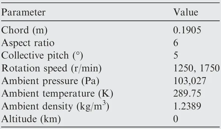
Table 1 Physical geometry parameters and operating condition of Caradonna-Tung model helicopter rotor case.
Table 2 represents the comparison of thrust coefficients at both rotational speeds between numerical results and experimental data.It illustrates that a relative error within 5%compared to the experimental data can be achieved for both cases.To further validate the accuracy of the MRF method,comparisons of the pressure coefficients Cpdistributed at 3 crosssections along the span of the blade (r/R=0.68, 0.80, and 0.96)at Ω=1750 r/min are also shown in Fig.2,which represents the aerodynamic loading distributions on the rotor blade.It indicates that the overall agreement with experimental data at all these different radial locations is satisfactory,and only a slight discrepancy of the suction peak value does exist.
2.2. Momentum source method
The Momentum Source Method (MSM) has been demonstrated applicable to a wide variety of rotary flow problems.29–32Its essential feature is that the effects of rotary system are considered only in terms of the momentum that it imparts to the flow, and thus, the rotary system can be replaced by distributed sources of momentum in the flow which mainly depend on the geometry properties and the flow field characteristics. The concept to solve the complicated rotary flow problems without the need for geometry-based numerical computations by using momentum sources to represent the rotational geometric entities provides a practical way for the development of propeller design without any consideration of propeller geometry.
2.2.1. Governing equations
The mass and three momentum equations in Cartesian coordinates can be written as


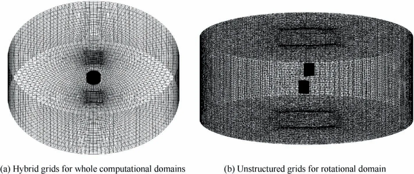
Fig. 1 Computational mesh around simplified model of Caradonna-Tung rotor.

Table 2 Comparison of thrust coefficient (CT=T/ρπΩ2R4).

2.2.2. Propeller modeling method
According to the momentum source approach,the influence of the propeller is to impart momentum to the flow, and thus,there are two aspects that need to be considered in determining the influence of propeller on the flow.One aspect is to find the region of the computational domain where such an influence is to be added. The other aspect is to determine the strength of momentum equation source terms at these locations. In the current work, the propeller disk is modeled as a cylinder with a thickness that is slightly larger than the overall thickness of the propeller,and thus,the propeller/wing integrated flow field can be divided into two separate computational domains: in and out of the cylinder domain. The grids within the cylinder domain are treated as the specific elements where the propeller sources are to be added.
Fig. 3 depicts the actuator disk of an operating propeller,where Ω is the rotational speed of propeller,and φ is the phase angle of the blade element. It indicates that for each element located on the actuator disk, the velocity vector (Va, Vr, Vt)in the propeller rotating reference frame can be transformed by the velocity vector (u, v, w) in the inertial reference frame.The transformation matrix between these two different coordinate systems is given by

When all the operating conditions are given and the sectional airfoil profile is also selected, the local aerodynamic properties dL and dD can be calculated, and then the thrust dT and the moment dM acting on the blade in the propeller rotating reference frame can be given, respectively, by
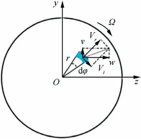
Fig. 3 Actuator disk sketch.
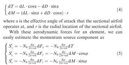
where Nbis the number of propeller blades,and vol is the volume of the grid element.
2.2.3. Numerical validation
To assess the accuracy and reliability of the MSM, the hovering rotor case33with ground effects taken into consideration is tested and validated against experimental data. Table 3 gives the physical geometry parameters and operating condition of the hovering rotor case. It should be noted that the MRF method mentioned above is also used here to determine the strength of the momentum sources which are added to the rotor elemental mesh volume. Fig. 4 shows the computational models of the hovering rotor case for both numerical methods,and it can be clearly seen that a ring-shaped computational region is defined around the rotor geometry in Fig.4(b)to load the uniformly distributed momentum sources. Fig. 5 depicts the calculated radial aerodynamic loading distributions of the hovering rotor blade by using the MRF method.

Fig. 2 Comparison of Cp distributions at different radial locations (Ω=1750 r/min).
Fig. 6 depicts the radial dynamic pressure distributions at varied height locations under the hovering rotor disk. For comparison, the MRF results at a phase angle of 0° withrespect to the geometric model are also discussed. It can be seen that the momentum-source rotor results, the MRF(ε=0°) results and the experimental data match well within most of the rotor disk range.However,it is found that notable differences exist in the tip vortex pattern, especially in the dynamic pressure peak. This may be due to the data errors caused by the exchange of the time-averaged flow information between both sides of the boundary interfaces,and it may also be related to the simplification of the quasi-steadily rotational motion of the hovering rotor which appears to be unsteady in nature,because the pressure measurement in the experiments is not always at the fixed phase angle relative to the rotor blade,which makes a difference and needs further research.
Through above analysis, it can be concluded that reliable induced slipstream characteristics can be achieved by using the MSM with given blade aerodynamic loadings, and moreover, less-than-1/4 computing time for the RANS simulation is required by using the MSM compared with the MRF method.
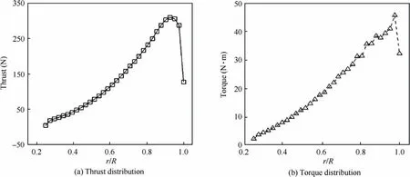
Fig. 5 Radial aerodynamic loading distributions of the rotor blade (MRF results).
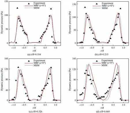
Fig. 6 Comparison of radial dynamic pressure distributions at different height locations.
2.3. Rapid analysis method based on blade element momentum theory
2.3.1. Extended BEMT method
The momentum theory for propellers is based on Newton’s second law that the thrust of the propeller blades is generated by the change in momentum between the freestream velocity and the wake velocity,and it is able to quantify the thrust generated in the control volume around the propeller blades, but unable to describe the detailed blade shapes of propellers. Blade element theory supplements the momentum theory by introducing the aerodynamic performance of the sectional ‘‘blade elements”, which is determined from an aerodynamic database developed a priori from aerodynamic analysis carried out for certain sectional airfoils.Thus,its accuracy is highly dependent on that of the aerodynamic analysis,especially for the values of CLand CDof the sectional airfoil at various angles of attack.An artificial neural network based on the two-dimensional RANS analysis is used to predict the aerodynamic forces generated by the sectional airfoil at varied states with nonlinear characteristics, including the large-angle state and the low-Reynolds-number state. Furthermore, an iterative circulation modification method is also developed to overcome the instability of the BEMT solving procedure.Please refer to previous work34,35of our task group for a detailed description of the extended BEMT method if necessary.
2.3.2. Numerical validation
To assess the accuracy and reliability of the present BEMT method,the conventional two-blade JXF 16×8 propeller case is tested and validated against experimental data.34,35Table 4 gives the operating condition of the JXF 16×8 propeller experiment.Fig.7 illustrates the comparison of the propulsive performance of the JXF 16×8 propeller at varied advance ratio J. For comparison, the MRF results are also discussed.Close agreements among the BEMT results, the experimental data and the MRF results are shown for both the calculated values and the predicted trends, and the maximum relative error is less than 10% at all these advanced ratios. Besides, a comparison of the radial aerodynamic loadings distributed on the JXF 16×8 propeller blade at a velocity of 12 m/s,and a rotational speed of Ω=4000 r/min is conducted as shown in Fig. 8. Both the numerical results show good agreements in the radial aerodynamic loading distributions, and only a less-than-10% maximum error can be found near the blade tip region where strong three-dimensional effects exist.
3. Design methodology
Fig. 9 illustrates the hybrid design framework of the tractor propeller for high-performance DEP aircraft.When the designcondition and goals are determined, the aerodynamic loading distributions of the MIL propeller need to be determined and parameterized, which are considered as the initial inputs for the following optimization procedure. Then, the parameterized aerodynamic loading distributions are optimized with the propeller/wing integrated performance taken as evaluation criteria. Once the optimal results were obtained, a new propeller blade geometry is rapidly generated based on target loading distributions through an inversed design approach.
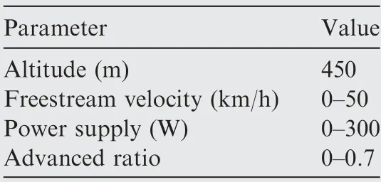
Table 4 Operating condition of JXF 16×8 propeller experiment.
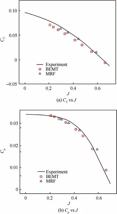
Fig.7 Propulsive performance of JXF 16×8 propeller at varied advance ratio.
For the purpose of this paper, it is assumed that the upstream effects of the wing within slipstream on the tractor propeller performance will be negligible, and the tractor propeller will be designed at a specified thrust level, diameter,rotational velocity, and number of blades. Furthermore, for simplicity, the propeller blade geometry will be defined by chord and twist distributions at several radial locations, and only a single sectional airfoil Clark-Y will be used.
3.1. Initial inputs from numerical simulation of MIL propeller
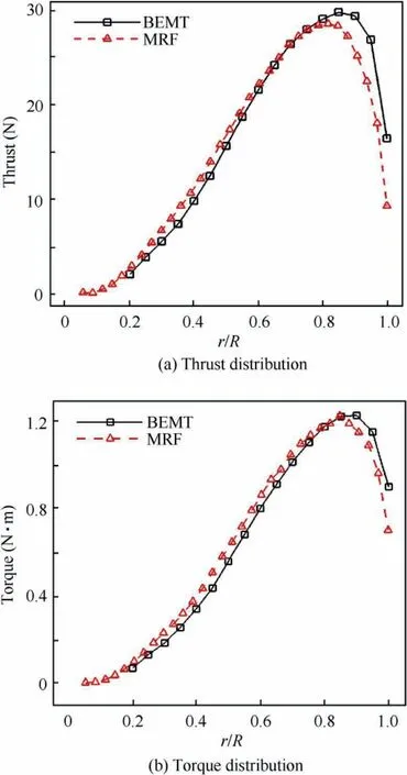
Fig. 8 Radial aerodynamic loading distributions of JXF 16×8 propeller blade (V∞=11 m/s, Ω=4000 r/min).
As the MIL propeller at a specified thrust level taken as the initial object, the high-fidelity simulations under the design condition are firstly conducted using the MRF method. Then both the radial thrust distribution and the radial torque distribution acting on the MIL propeller blade can be extracted and parameterized, which are needed as the inputs for the momentum-source propeller simulation in the following optimization process.However,it is found to be difficult to realize the parameterization because of the existing complicated function relationships between the radial thrust and the torque(see Eq. (4)) distributions on the blade, therefore, to simplify the design problem, we assume that all the sectional airfoils of the expected propeller will operate at its maximum lift-todrag ratio,and then the lift-to-drag ratio of each sectional airfoil can be treated as a constant because only a single sectional airfoil Clark-Y is used in this work.As a result,the torque generated by any sectional airfoil can be written as a monotone function of the local thrust as follows:

thus, only the parameterization of the radial thrust distribution profile is required to realize the control of the blade aerodynamic loadings.
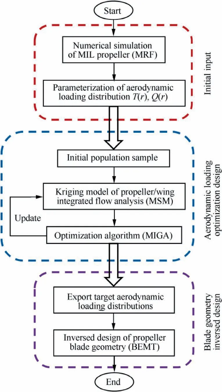
Fig. 9 Hybrid design framework of tractor propeller for highperformance DEP aircraft.
The Hicks-Henne bump functions36are used to control the radial thrust distribution profile, which can be represented by the following equations:

where ynewand yoldare the values of the new and old thrust generated by the sectional airfoils, xkare the radial locations of the prescribed control points with respect to the propeller radius, fk(x) are the shape functions which will be added linearly to the baseline profile to achieve the desired design improvement, and ckare the participation coefficients (design variables) which are associated with all the shape functions.
Considering that the sectional airfoils located at propeller root and tip are operating at relatively extreme conditions that only near-to-zero aerodynamic forces can be generated, the values of both ends of the control curve are kept unchanged throughout the whole design process. Besides, in order to maintain that the propeller is designed at the specified thrust level, a simple correction method is developed and used in the optimization process, which can be simplified into three steps: calculating the area enclosed by the radial thrust distribution curve by adopting integral method, analyzing the variation ratio of the thrust with respect to the specified value,and scaling the distributed thrust value at the variation ratio.
3.2. High-fidelity propeller disk loading optimization design
By using the MSM,the propeller induced slipstream characteristics can be optimized and redistributed by controlling the aerodynamic loadings distributed on the blade, and then it becomes possible to design the propeller induced slipstream characteristics into a desired form which brings aerodynamic benefits to the wing downstream. In the present optimization design process, the lift-to-drag ratio of the wing under slipstream effects is taken as a cost function under prescribed geometric and aerodynamic constraints including the propeller radius,the propeller thrust and torque,which aims to improve the lift-to-drag performance of the wing under slipstream effects as much as possible under the premise that the propulsion efficiency of the tractor propeller varies within a certain range. Thus, the mathematic expression of this single-object optimization model can be written as

As shown in Fig. 9, the Multi-Island Genetic Algorithm(MIGA)37is used to solve the single-objective model within the prescribed design spaces, and the control parameters of the MIGA are set as follows: (A) the size of the population is 100 (i.e. 10 islands and 10 individuals per island); (B) the probabilities of the crossover, mutation and migration operator are 0.9, 0.2 and 0.5, respectively; (C) the maximum evolution generation is 20.Besides,the Kriging surrogate model38,39is used to improve the computational efficiency of the searching stage. A total of 100 sample points are estimated for constructing the Kriging surrogate model, and furthermore, some adaptive sampling procedures and the updating mechanism by adding well-performance optimized solution into the initial sample collection are used to improve the accuracy of the Kriging surrogate model. Once the maximum lift-to-drag ratio of the wing within slipstream is achieved,the most beneficial slipstream properties induced by the expected propeller with the optimal radial thrust/torque distribution can be obtained.
3.3. Rapid propeller blade geometry inversed design with arbitrary circulation distribution
Fig. 10 depicts the aerodynamic force and flow velocity experienced by a blade element in propeller rotating reference frame, where Ω is the rotational speed of propeller, r is the radial location of the blade element, a is the effective angle of attack, β is the interference angle, θ is the geometric inflow angle, φ is the actual inflow angle, γ is the drag-to-lift angle,Vgeois the geometric inflow velocity, Vitis the tangential induced velocity, Viais the axial induced velocity, Vais axial velocity of the incoming flow, Vrealis the effective velocity of the incoming flow,V′is the pitch increment due to the induced velocity, and dL, dD, dT, dQ and dF represent the lift, the drag, the thrust, the torque, and the total force experienced by the blade element respectively.
Based on the blade element theory and the momentum theory, an implicit relation for the interference angle can be obtained as
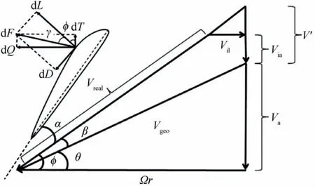
Fig. 10 Aerodynamic force and flow velocity experienced by blade element.
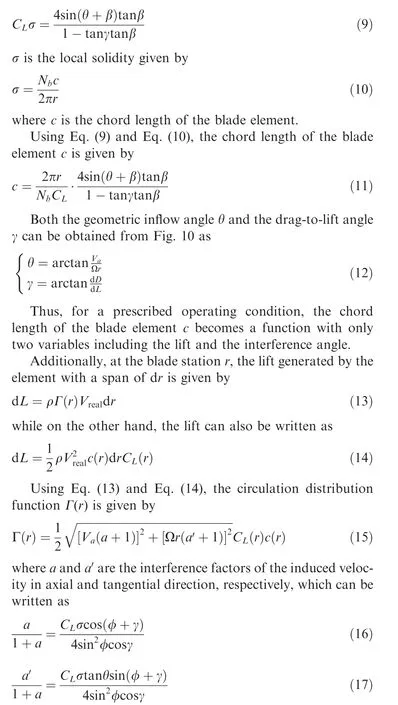
As a result, the circulation distribution function Γ(r)becomes a function with respect to only three variables including the lift, the drag and the interference angle of a blade element. Based on the aerodynamic database of the sectional airfoil established above, the circulation distribution of the expected propeller can be uniquely determined according to the optimized aerodynamic loading distributions of the blade.Therefore, the interference angle can be computed by an iterative method, and then the distribution of the twist angle and chord length along the blade can be determined. Please refer to previous work40of our task group for a detailed description of the propeller blade geometry inversed design with arbitrary circulation distribution if necessary.
4. Design application and results
In the preceding sections, we presented details of the variablefidelity aerodynamic analysis methods and the hybrid design framework used in this study. To demonstrate the validity of the hybrid design framework for the propeller design, we applied it to the design optimization of a low-thrust-level propeller used by the solar-powered aircraft shown in Fig. 11,based on which the propulsive system can be changed as required to achieve our research objectives. The design state and the required thrust are determined as: H=500 m,V∞=10 m/s, R=0.203 m, Ω=2500 r/min, Nb=2,T=5 N.
Analyses by Deere8and Wang41et al. indicated that the near-wall flow on a finite wing under the multiple propellers slipstream effects shows notable characteristics of periodicity and repeatability, which may be because of the cutting effects of the slipstream induced by the outer propellers. Thus, in order to reduce the complexity of the design problem, both the wingtip vortex effects and the interactions between distributed propellers are neglected in this study. As shown in Fig. 12, the computational model which is comprised of only one momentum-source propeller model and the wing section is established. Referring to the parameters of the solarpowered aircraft mentioned above,the propeller is located forward of the wing at a distance of 0.4 m, and the thickness of the momentum-source model is set to be 0.04 m. Besides, the wing section is modeled with a chord of 0.6 m, a span of 2.0 m, and an installation angle of 3°. The hub geometry is eliminated and the surfaces on both sides of the wing section are set with symmetry boundary conditions.
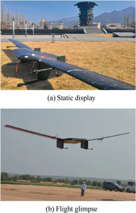
Fig. 11 Solar-powered aircraft.
4.1. Propulsive performance of isolated propeller
Based on the MRF methods, the aerodynamic loadings distributed on the MIL propeller blade are analyzed and taken as initial inputs to the design procedure. Fig. 13 shows the comparison among the initial, the optimized and the designed radial aerodynamic loading distribution profiles. It indicates that the aerodynamic loadings distribution profiles are optimized to be relatively uniform along the blade, which is quite different from the MIL propeller with a high degree of nonuniformity in the aerodynamic loading distributions.It should be noted that the propeller cannot be designed completely in accordance with the optimized aerodynamic loadings under the premise that the sectional airfoil of Clark-Y remains unchanged, and this is mainly because the blade-root section which is operating at a very low local velocity is unable to provide the desired thrust unless its chord length reaches a level unacceptable. Thus, it is necessary to add some chord length constraints into the tractor propeller design process.As shown in Fig.11,three types of constraints about the maximum chord length of the blade (cmax=0.6R, 0.5R, 0.4R) are taken into account in this work, the results illustrate that the designed aerodynamic loading profiles become more and more regular as the constrained maximum chord length decreases.
Fig. 14 depicts the comparison of twist angle and chord length among three types of designed propeller blade planforms and the MIL propeller blade planform. Fig. 15 shows the three-view sketches of the propeller geometries.It indicates that,compared with the MIL propeller,the variation gradients of the radial twist angle distribution of the designed propellers get relatively larger,while the chord lengths of near half of the designed propeller blades within the near-to-hub region are significantly increased.
Table 5 summarizes the results of the aerodynamic analysis of different propellers using the MRF method. It indicates that,under the constraint of the prescribed thrust,the propulsion efficiency of all these designed propellers is reduced when compared with that of the MIL propeller, and as the constrained maximum chord length decreases,the propulsion efficiency gradually increases. This may be due to the motion of the aerodynamic center towards the propeller hub.
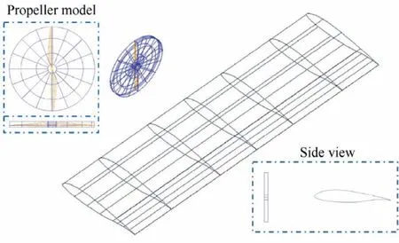
Fig. 12 Computational model of propeller/wing integration.
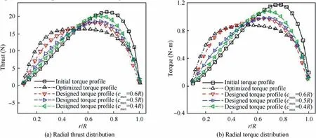
Fig. 13 Comparison of radial aerodynamic loading distribution profiles.
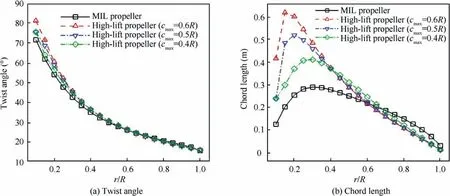
Fig. 14 Comparison of twist angle and chord length along blade of different propellers.
4.2. Aerodynamic performance of propeller/wing integration
Table 6 illustrates the comparison of aerodynamic performance of the wing section under slipstream effects induced by the MIL propeller and the designed propellers. CL, CD,CDpand CDvare lift coefficient,drag coefficient,pressure drag coefficient and viscous drag coefficient, respectively. Besides,we also use a parameter (CL/CD)/W to characterize the liftto-drag ratio generated by unit power. It indicates that the lift-to-drag performance of the wing under slipstream effects induced by the designed propellers is significantly improved when compared to the MIL propeller induced results. As the constrained maximum chord length of the designed propeller increases, the wing lift is increased by 2.61%, 2.72%, and 2.82% while the wing drag is reduced by -1.97%, 0.25%,and 4.56%, respectively. As compared with the lift-to-drag ratio of 31.389 generated by the wing under slipstream effects induced by the MIL propeller, the lift-to-drag ratio of 31.586,32.324, and 33.817 represent 0.63%, 2.98%, and 7.74%increase, respectively. Besides, compared with the MIL propeller induced results, the aerodynamic efficiency of the wing obtained per unit power is found to be significantly increased with the designed propeller induced slipstream effects taken into account, in other words, the propeller/wing integrated performance is improved by adopting the present hybrid design framework even though the propulsive efficiency of the designed propellers is getting worse. It also shows that the lift-to-drag ratio generated by unit power gradually decreases as the constrained maximum chord length of the designed propeller decreases.
In order to further study the beneficial flow mechanism,Fig. 16 illustrates the comparison of the lift coefficients distributed along the wing span under slipstream effects induced by the MIL propeller and the designed propeller (cmax=0.6-R).The wing is averagely partitioned into 30 parts in the spanwise direction, and the lift coefficient of each partial wing is calculated with the total area of wing and the incoming freestream velocity as the reference area and reference velocity,respectively.It can be found that,compared with the MIL propeller results, the lift generated by the wing section at the designed propeller induced upwash peak becomes much larger,and also, both the upwash peak and the downwash peak are moving towards near the propeller hub, which means that the rotational effects induced by the designed propeller are strengthened and centralized.
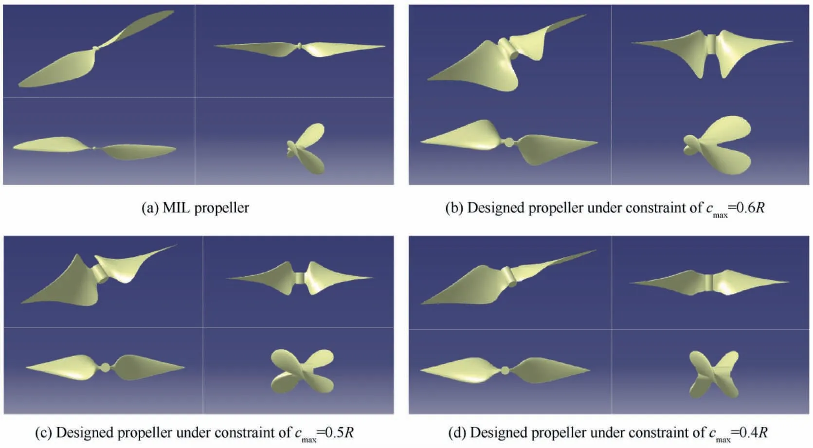
Fig. 15 Sketches of different propeller geometries.

Table 5 Propulsive performance of different propellers (MRF results).

Table 6 Aerodynamic performance of the wing section under slipstream effects (MRF results).
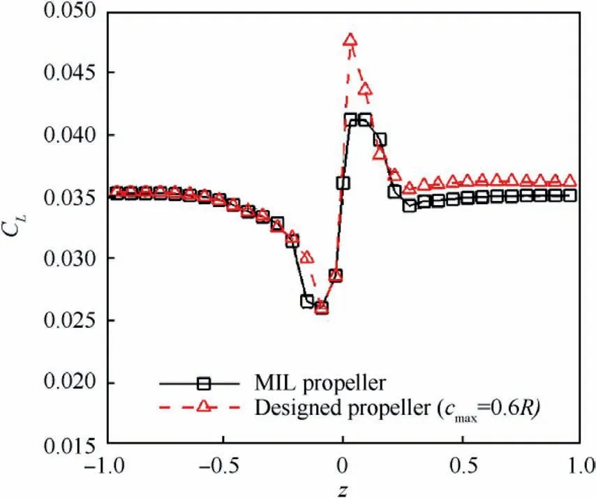
Fig. 16 Comparison of lift coefficients distributed along wing section in the spanwise direction.
Fig. 17 illustrates the comparison of velocity distributions at x=0.1 m behind the MIL propeller and the designed propeller(cmax=0.6R).Fig.18 and Fig.19 show the comparison of both the Cpdistributions and the Cfdistributions on both surfaces of wing under slipstream effects induced by these two propellers, respectively.
(1) It can be concluded that:
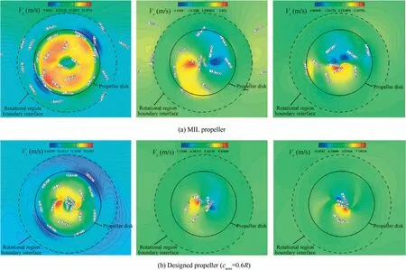
Fig. 17 Comparison of velocity distributions at x=0.1 m behind propeller (MRF results).
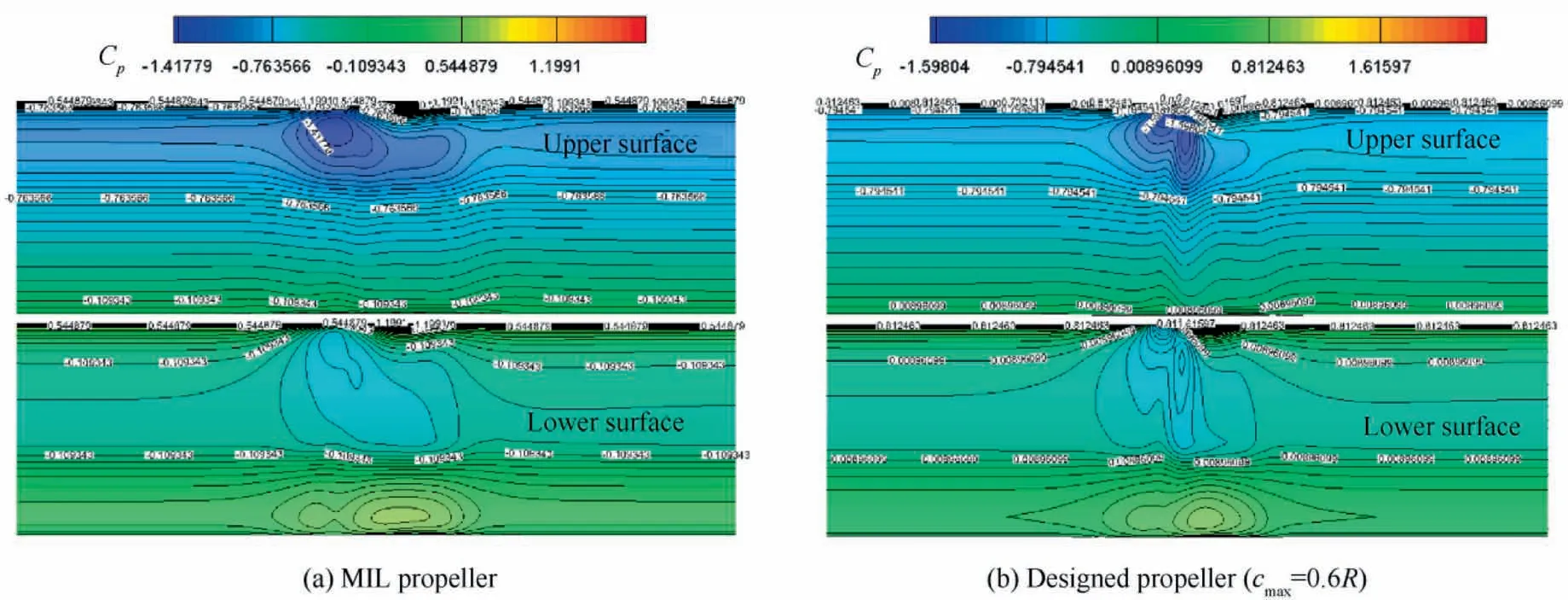
Fig. 18 Comparison of Cp distributions on both surfaces of wing under slipstream effects (MRF results).
When compared to the MIL propeller, the designed propeller can generate a much stronger and more concentrated tangential flow near the hub (as shown in Fig. 17), which corresponds to the variation trend of the spanwise lift distribution as shown in Fig.16.As a result,both the maximum/minimum static pressure region and the maximum skin friction drag region are found to converge to the middle of the wing. In other words, even though the rotational effects induced by the designed propeller are significantly enhanced compared to that induced by the MIL propeller(shown as the sharp peak in Fig.16),the range of the wing affected by the strong rotational effects is decreased because the notable rotational flow induced by the designed propeller is restricted close to its hub,and the rest of the wing within slipstream is mainly operating in the accelerating flow regime, which results in better drag performance in spite of the increased induced drag from the sharp peak.
(2)The axial velocity differences between inside and outside the boundary of the designed propeller disk are found to be smaller than that of the MIL propeller disk,which means that the strength of the streamwise velocity shear along the boundaries of the slipstream region induced by the designed propeller is much weaker than that induced by the MIL propeller.Thus,both the strength of the blade tip vortices and the total pressure losses due to the blade tip vortices consumption will be reduced, which will greatly benefit the pressure drag experienced by the wing (listed in Table 6).
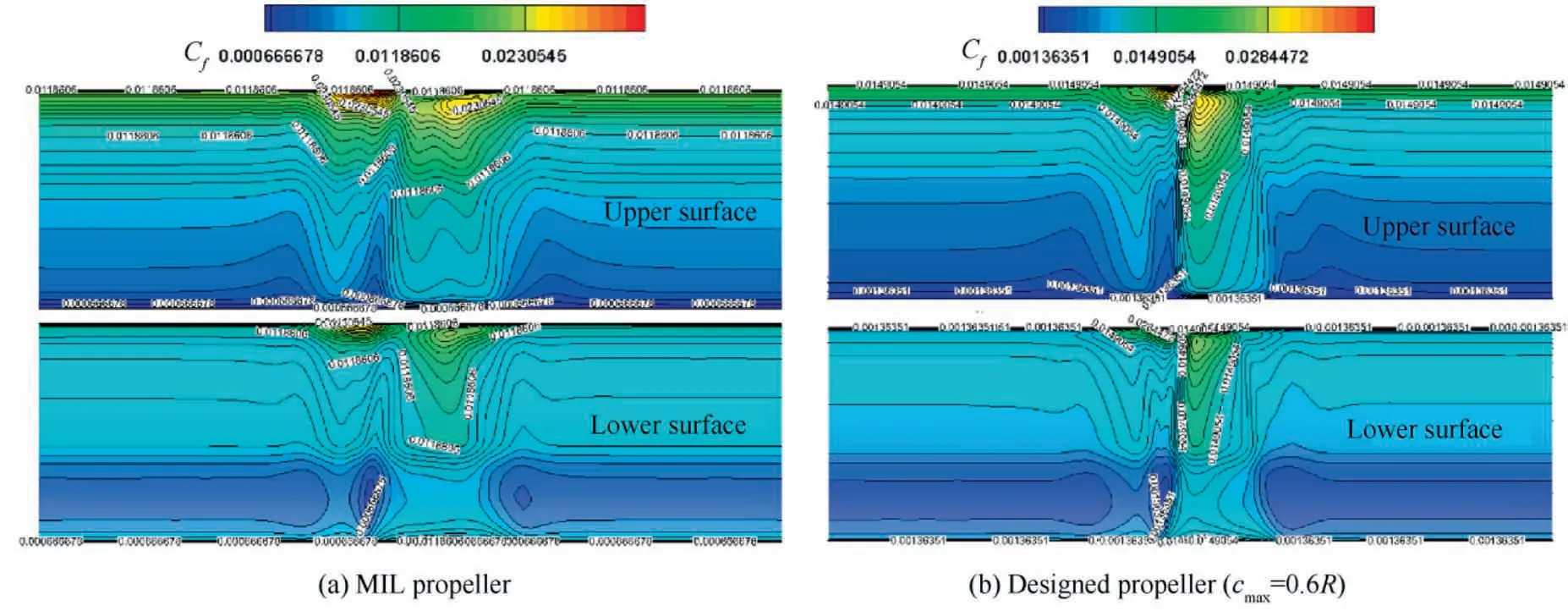
Fig. 19 Comparison of Cf distributions on both surfaces of wing under slipstream effects (MRF results).
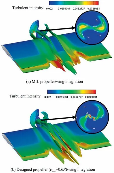
Fig. 20 Comparison of time-averaged turbulent intensity distribution around propeller/wing integration (MRF results).
Fig. 20 depicts the comparison of time-averaged turbulent intensity distribution around the propeller/wing integration based on Q-criterion,42and the circular frame shows the time-averaged turbulent intensity distributed on the cross section located behind the propeller disk with a distance of x=0.1 m. Compared with the MIL propeller results, the designed propeller induces much stronger concentrated turbulent flow which locates near the hub,and besides, the strength of the induced turbulent flow distributed behind the designed propeller blade tip is also reduced. This further validates the previous analyses.
5. Conclusions
This paper has developed a hybrid design framework of propeller for high-performance DEP aircraft. The design procedure consists of three steps. First, the baseline aerodynamic loading distributions on the propeller disk are prescribed, as obtained from the high-fidelity simulation of the MIL propeller at a specified thrust level.Second,the aerodynamic loading distributions are optimized and redistributed into a beneficial form by using the MSM with the objective of maximum aerodynamic benefits for the wing downstream. Third,the new propeller blade geometry is rapidly generated based on the target aerodynamic loading distributions through an inversed design approach.
This design method is validated through a design example of a low-thrust-level propeller developed for a solar-powered aircraft. It indicates that, compared with the wing under slipstream effects induced by the conventional MIL propeller,significant aerodynamic improvements including 2.82% lift augmentation, 4.56% drag reduction and 7.74% lift-to-drag ratio augmentation can be achieved by using the designed propeller, and the propeller/wing integrated efficiency per unit power is also improved even though the propulsive efficiency is slightly reduced,which shows great promise to deliver aerodynamic benefits without any lift augmentation or drag reduction devices.
Recently, Wang43and Xue44developed a rapid propeller design method to obtain the target aerodynamic loading distribution and target induced velocity distribution, respectively.Both the design results and the variation trends of the designed propeller are similar to the results of this study, which further proves the effectiveness of the design approach based on the distribution of slipstream characteristics, such as the induced velocity, aerodynamic loading, etc.
However, due to the assumptions that have been made to simplify the design problem,only the propeller blade planform is designed in the current work,which results in the unfeasibility of the optimal aerodynamic loading distributions,and then leads to significant reduction of the propulsive performance of the designed propellers with additional geometry constraints.Besides, in order to realize the design purpose, both the wingtip vortex influences and the distributed propellers interactions have been neglected in this work, which causes a range of issues for the application of the present design method to a real DEP configuration. Hence, it is of importance to carry out more research on both design philosophies and design methodologies to achieve the optimal DEP solutions.Only in this way can we reach the real goals of the high-performance DEP aircraft.
On the other hand, there is no doubt that the rotational motion of propeller appears to be unsteady in nature;however,the predominant majority of simulations for the present design applications have been done for steady flows.Thus,it is necessary to conduct more detailed analyses about both steady and unsteady flow properties of the desired induced slipstream characteristics,and also,both numerical and experimental validations on the present design strategy need to be done in the future work.
Declaration of Competing Interest
The authors declare that they have no known competing financial interests or personal relationships that could have appeared to influence the work reported in this paper.
Acknowledgement
This study was supported by the Key Research and Development Program of Shaanxi Province of China (No.2018ZDCXL-GY-03-04).
 CHINESE JOURNAL OF AERONAUTICS2021年10期
- CHINESE JOURNAL OF AERONAUTICS的其它文章
- Direct dynamic-simulation approach to trajectory optimization
- A strong robustness open-circuit fault diagnosis strategy for novel fault-tolerant electric drive system based on d-q-axis current signal
- Nonlinear vibration response characteristics of a dual-rotor-bearing system with squeeze film damper
- Ground maneuver for front-wheel drive aircraft via deep reinforcement learning
- Numerical simulation of a UAV impacting engine fan blades
- Recent advances in precision measurement &pointing control of spacecraft
