Microstructure evolution and reaction behavior of Cu-Ni alloy and B4C powder system
Lei Ji ,Ming-fng Yng ,Zhen-lin Lu ,Jin Xu ,Hui Xie ,Ktsuyoshi Kondoh
a School of Materials Science and Engineering,Xi’an University of Technology,Xi’an,710048,China
b School of Materials Engineering,Xi’an Aeronautical University,Xi’an,710077,China
c Joining and Welding Research Institute,Osaka University,Osaka,567-0047,Japan
Keywords:Metal-matrix composites Reaction behavior Microstructure evolution Cu-Ni/B4C composite In-situ experiment
ABSTRACT Microstructure evolution and reaction behavior of Cu-Ni alloy and B4C power system was studied by in-situ and static experimental investigations along with theoretical calculations.The reaction process was as follows.Firstly,B4C decomposed into B and C atoms,and then B atoms diffused into Cu-Ni matrix,leading to the formation of Ni2B particles.Subsequently,Ni atoms diffused into B4C,forming a loose mixture of Ni2B and amorphous C at the initial powder boundary.Finally,with the completion of reaction,Ni2B particles at the powder boundary grew into a monolithic block,and then C substance was excluded out and accumulated at the edge of this monolithic Ni2B block.It is believed that the formation of Ni2B phase is caused by the most negative change of Gibbs free energy among all the potential reactions between Ni-B and Ni-B4C systems.
1.Introduction
Copper materials have received much attention in plenty of domains of electrical transmission due to their superior electrical and thermal conductivity as well as good processability [1,2].However,their utilization in some special applications is limited by their low strength and poor wear resistance,such as contact lines for high speed railway,contacts for high voltage circuit and brushes for precise motors,and so on[3,4].Therefore,there is great interest in increasing the strength and wear resistance of copper materials,while maintaining as good electrical conductivity and processability as possible.Two solutions can be adopted to deal with this issue.One is to add alloying elements such as Cr,Sn,Fe,Ni,Zr,Si,Ag into pure copper to increase the strength of Cu matrix by solid-solution strengthening or precipitation strengthening [5-8].The other is to introduce ceramic particles with high hardness and modulus or self-lubricating ability into copper matrix by means of extra or in-situ methods,such as Y2O3[9],Al2O3[10,11],SiC [12],TiC [13],TiB2[14],ZrC [15],C [16],MoS2[17] and etc.However,the increase of strength comes at the expense of electrical conductivity.
Because of the high elastic modulus and hardness as well as good wear resistance,TiC,TiB and TiB2ceramics are always introduced to reinforce copper matrix,especially by the reaction of Ti-B or Ti-B4C system in Cu-Ti-B or Cu-Ti-B4C systems [18,19].Though a good strengthening effect can be obtained,because of the solution of Ti in Cu matrix,the electrical conductivity is still significantly reduced [20].Compared to Cu-Ti-B4C,Cu-Ni-B4C system is more likely to have high strength,electrical conductivity along with good wear performance due to the following advantages:(1)The solid solution of Ni atoms results in lower damage to the electrical conductivity of Cu than that of Ti[21],(2)Ni can react with B4C to form many Ni-B compounds with high hardness according to the Ni-B binary phase diagram[22],especially Ni2B,whose electrical conductivity is higher than that of most other traditional ceramic compounds [23];(3) The other product viz.amorphous C substance (a-C),is one of the highly studied lubrication materials recently,which has high hardness and low friction coefficient [24,25],and can help to improve the wear resistance of the composites.
Despite the above potential advantages,no research on Cu-Ni-B4C powder system has been conducted.In our previous work,it was confirmed that the in-situ reaction between Ni and B4C could happen in the Cu-Ni alloy and B4C powder system under solid-state sintering,and the reaction products are Ni2B and a-C[26].The result indicated that Cu matrix composites with a balance of strength,electrical conductivity and wear performance were expected to be prepared from Cu-Ni-B4C powder system,because of the coexistence of reinforced Ni2B and self-lubrication phase C substance.However,Ni2B did not only form inside but also at the primary powder boundaries of the initial Cu-Ni alloy powder,while all the a-C substance existed at the primary powder boundaries.It is well known that the impurities at the grain boundary or secondary phase at the primary powder boundary are harmful to their strengthening effect,and hence it is necessary to regulate the distribution of these reaction products.Nevertheless,to better regulate the microstructure and utilize the potential advantages of Ni2B and a-C,the in-situ reaction behavior of Cu-Ni and B4C powder system under solid-state sintering must be clarified first.
In this paper,the microstructure evolution as well as reaction behavior of Cu-Ni alloy and B4C powder under solid state sintering were studied experimentally,and thermodynamic calculations were also performed to study the competitions among different potential chemical reactions.Based on the experimental results and theoretical analysis,a schematic diagram on the microstructure evolution of Cu-Ni alloy and B4C system during the in-situ solid-state reaction was proposed.
2.Experimental details
2.1.Powder mixing and mechanical consolidation
Gas-atomized Cu-Ni alloying powder(10 wt%Ni,~75 μm)and B4C powder with the purity of 99.5%and average size of 5 μm were used as raw materials.Firstly,the Cu-Ni alloying powder was mixed with 0.08 wt%vacuum pump oil by table milling machine(Pulwerisette5,Fritsch)at 90 r/min for 1 h.Subsequently,B4C powder and ZrO2balls were added and mixed by rocking milling machine (Seiwa Giken,RM-05) continuously at 50 Hz for 1 h.Then,the powder mixture was successfully made,and the mass ratio of Cu-Ni to B4C was 85:1 according to the potential reaction as shown in Eq.(1) along with the Ni content in Cu-Ni alloy powder.Finally,the powder mixture was consolidated by steel dies under a table hydro press machine with 500 MPa at room temperature,obtaining cold-compacted blocks.

2.2.In-situ observations in SEM chamber
One of the cold-compacted blocks was cut into a piece-like sample of 8×5×1 mm by precision cutting machine,and then the top surface was treated by metallurgical methods including grinding,polishing and etching.Then,this piece-like sample was attached onto a small heating plate and thermocouple was welded in the corner.Subsequently,the heating system along with the sample was placed into the chamber of scanning electronic microscopy (JEOL,6500),and then vacuumed in order to meet the requirements of SEM observation.For comparison,the initial microstructure was observed at room temperature,and EDS analysis was also performed.Afterwards,the sample was heated to various target temperatures ranging from 600 to 900°C at a rate of 2°C/s.Once the target temperature reached,SEM photography was adjusted and captured within 30 s.Finally,when the sample was cooled down,SEM observation and EDS analysis were carried out again.
2.3.Static investigations by water-quenching
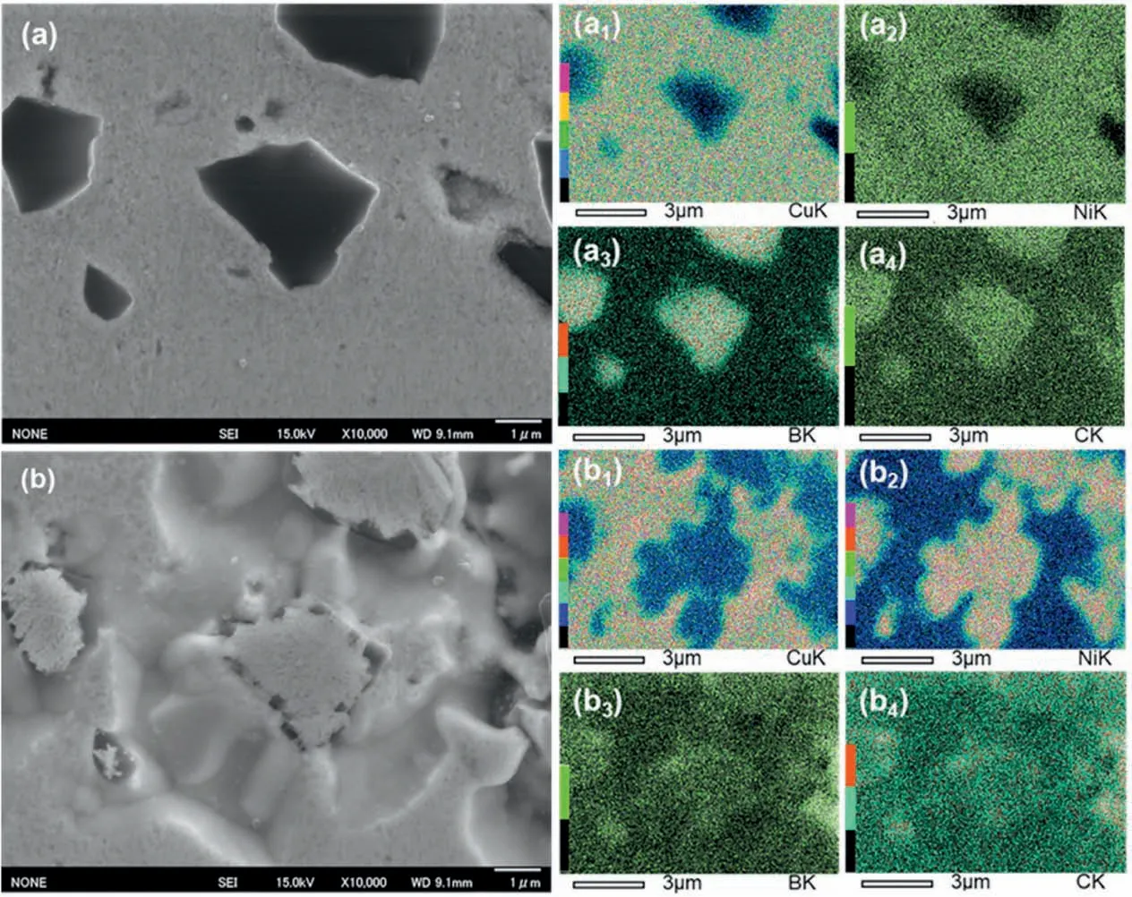
Fig.1.SEM images of the compacted Cu-Ni/B4C block(a)before and(b)after in-situ heating to 900 °C in the SEM chamber,and the subscript numbers 1-4 refer to the distribution of Cu,Ni,B and C by EDS mapping,respectively.
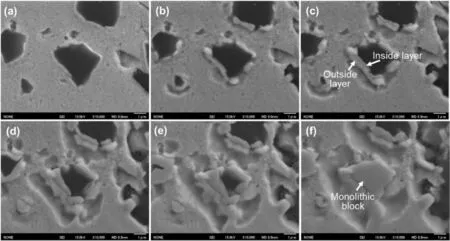
Fig.2.Microstructural evolution of Cu-Ni/B4C powder system during the in-situ heating process in SEM chamber,(a)600,(b)650,(c)700,(d)750,(e)800 and(f)850 °C,respectively.
Considering the limitations of the in-situ SEM observation on phase identification,such as chemical composition and phase structure,it is necessary to use the water-quenched samples for static investigations.Firstly,the cold compacts were heated to 600,700,800,900,950 and 1000°C,respectively,where the heating rate was the same as that of insitu SEM observations(2°C/s),with Ar gas as the protective atmosphere.Then,the compact was immediately quenched into ice water after holding for 5 min.For metallographic observation,the water-quenched specimens were mechanically ground with up to #2000 SiC abrasive papers,and then polished with 50 nm Al2O3suspension.After being polished,the specimens were etched in a solution of 20%H2O2(3%)-40%NH3(28%)-40%H2O.Microstructure observation and EDS analysis were carried out on a field-emission scanning electronic microscopy (JEOL,6500) equipped with energy spectrum analyzer (Oxford).Phase composition was studied by X-ray diffraction (Shimadzu,XRD-6100).Specific microstructural information was characterized by using a transmission electron microscopy (Tecnai,G2 F20 S-TWIN),where the sample was prepared by an ion milling machine(GATAN691).
2.4.Preparation of composites from Cu-Ni/B4C powder system
In order to verify the reaction behavior and mechanism obtained by in-situ and static investigations,the powder mixture obtained in 2.1 was sintered by using park plasma sintering(SPS)machine,which is a widely used method to synthesize bulk composites.The heating rate was maintained at 50°C/min until the target sintering temperature reached 900°C,and holding time was 1 h.Graphite dies were used and a pressure of 30 MPa was applied during the whole sintering process.The element distribution was analyzed by electron probe micro analyzer (EPMA)attached to a field-emission scanning electronic microscopy(JEOL,JXA-8530F) in a mapping mode,since it is more sensitive to light elements,such as B and C compared with EDS.
3.Results and discussion
3.1.In-situ microstructure evolution
As heat effect gives rise to the serious emission of phonons,EDS is seldom used at high temperature.Hence,the chemical composition analysis on the reaction system can only be carried out before heating and after the sample has been cooled down to room temperature.Fig.1 shows the morphology and EDS mapping results of the compacted Cu-Ni/B4C powder mixture before and after in-situ heating in SEM chamber.It is apparent that,the distributions of Cu and Ni elements were overlapped (Fig.1a1and 1a2),while those of B and C were also overlapped in the initial state of the compacted block,agreeing well with its processing condition,viz.raw materials Cu-Ni alloy and B4C particles were mechanically mixed and cold consolidated.Interestingly,the distribution of the elements of the compacted sample after in-situ heating in SEM chamber was very different from that of initial state:the areas rich in Cu were low in Ni elements(Fig.1b1and 1b2),while the areas rich in B were rich in Ni(Fig.1b3and 1b2),suggesting that Ni has de-solventized from Cu-Ni alloy and reacted with B to form new products.C element mainly distributed in the initial position of B4C,but it was more abundant in the small black particles around the grey blocks (Fig.1b),which occupied the initial position of B4C particle and was rich in Ni and B elements than in central region(Fig.1b4).
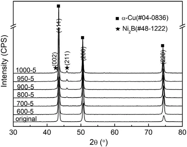
Fig.3.XRD patterns of Cu-Ni/B4C compacts after being held at different temperatures and water quenched for 5 min,where“600-5”means being heated at 600 °C for 5 min.
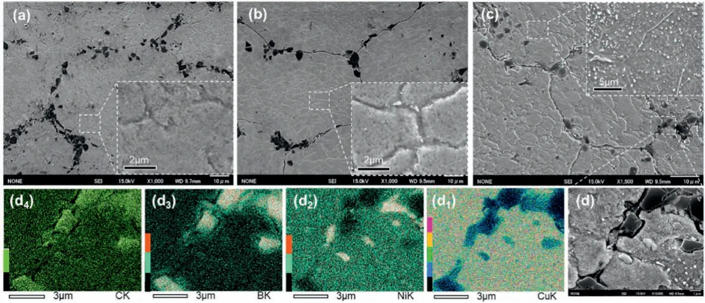
Fig.4.Microstructure of Cu-Ni/B4C compacts (a) before and after being held and quenched from (b) 600 and (c)700 °C for 5 min along with high-magnification insets showing the details inside the Cu-Ni matrix,while (d) is the high-magnification image at the primary powder boundary in (c) and subscript numbers 1-4 refer to the distribution of Cu,Ni,B and C,respectively.
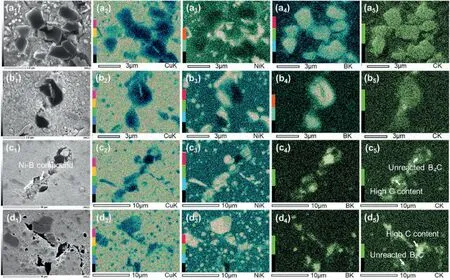
Fig.5.Microstructure along with EDS mapping of Cu-Ni/B4C compacts after holding at (a) 800,(b) 900,(c) 950 and (d) 1000 °C for 5 min,while the subscripts 1 stands for secondary electronic images,and (2-5) for the distribution of Cu,Ni,B and C,respectively.
Fig.2 shows the microstructural evolution of the compacted Cu-Ni/B4C mixture during heating in the SEM chamber.When the compacted block was heated to 600°C,its morphology was similar to that of the initial state(Fig.1a),except that there was a bright and thin layer around the B4C particles,as shown in Fig.2a.When the temperature was further raised to 650°C,vermicular white products formed on the edge of B4C particles and some sunk areas were found around them,indicating the insitu reaction had already started,as shown in Fig.2b.With the process of in-situ reaction,the vermicular products were divided into two layers.The inner layer looked dense,occupying the position of initial B4C particles,while the outer layer looked loose and closely connected to the inner one (Fig.2c).As the temperature increased,the inner layer grew toward B4C side,while the outer layer grew towards Cu-Ni side,leading to the decrease of the volume fraction of B4C particles and increase of the proportion of sunk areas(Fig.2d-e).When the temperature reached 850°C,the black B4C particle in the center of the image fully disappeared and the inner layer grew into a monolithic block,whose morphology and size were almost the same as that of the initial B4C particle(Fig.2f).When the temperature eventually reached to 900°C (Fig.1b),the small black particle rich in C precipitated around the inside monolithic block.Since both the inner and outer layers of the reaction products mainly consist of Ni and B elements (Fig.1b2and 1b3),and hence they cannot be distinguished by EDS mapping analysis.This was investigated by static method as following.
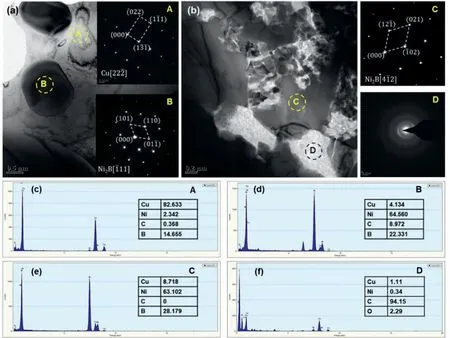
Fig.6.TEM images and corresponding SAED patterns of Cu-Ni/B4C compact after being held at 950 °C for 5 min and following by water quenching.(a)and(b)are the bright-field images in matrix and at the primary powder boundary of Cu-Ni matrix,where the insets show SAED patterns,(c-f)are EDS analyzing results of specific areas marked in (a) and (b),respectively.
3.2.Microstructure and phase evolution by static method
Though the results of in-situ heating in SEM chamber can provide the information of microstructure evolution,the phase composition cannot be confirmed.In order to better understand the microstructure and phase evolution during the reaction process,a series of detailed characterizations were carried out on the water-quenched samples.Fig.3 shows the XRD patterns of Cu-Ni/B4C compacts after being held at different temperatures and followed by water quenching.It can be found that there was only α-Cu phase in the initial state,while the absence of B4C phase may be due to its low content (1.16 wt%).When the temperature exceeded 800°C,the new peaks corresponding to Ni2B appeared,suggesting that the reaction had already started.The absence of the other potential product C can be attributed to many factors,such as low content,low mass absorption coefficient[27],amorphous state,or even the incorrect estimation on the reaction products by Eq.(1) and so on,which will be further studied by TEM later.
According to XRD patterns in Fig.3,no reaction occurred when being heated below 800°C.However,it is well known that,XRD cannot detect the phase when its content is low,and thus SEM observation should be used to further confirm the specific information,as shown in Fig.4.It can be seen that,the microstructure after being quenched from 600°C was almost the same as that of the initial state,viz.B4C particles distributed at the primary boundary of Cu-Ni alloy powder (Fig.4a and b).However,the higher magnification observation showed that there was some new particle-like phase at the grain boundary of the sample quenched from 600°C(inset in Fig.4b).When the temperature further increased to 700°C,both the number and size of the particle-like phase inside the Cu-Ni matrix increased significantly,and the morphology of B4C powder at the primary powder boundary also changed slightly (Fig.4c).Higher magnification observation and EDS mapping at the primary powder boundary of Cu-Ni alloy powder show that,the edge of B4C particles became smooth and some areas seemed to be“etched”by a grey phase rich in Ni element,as shown in Fig.4d,and the particle-like phase inside Cu-Ni matrix was rich in Ni and B.Moreover,Cu and Ni distributed alternately instead of overlapping (Fig.4d1and 4d2).Such information indicates that Ni atoms were no longer distributed evenly in Cu-Ni alloy matrix,but were concentrated in some particle-like phases in the matrix,or diffused into B4C particles and reacted with them.
Fig.5 shows the microstructure and EDS mapping results of the samples quenched from 800,900,950 and 1000°C,respectively.It can be found that,the microstructure of the samples quenched from 800 or 900°C was almost the same as that at 700°C,while the differences were the sizes of the particles in the matrix and the“etching”area at the edge of B4C particles.With the increase of holding temperature,the“etching”area became larger,as shown in Fig.5a and b.When the holding temperature reached 950°C,most of B4C particles transfer to Ni-B compound,and the number of particles rich in Ni and B in Cu matrix also increased significantly (Fig.5c).Moreover,the Ni-B compound at the primary powder boundary seemed to be loose (marked by the arrows in Fig.5c1) and surrounded by a black phase,where the brightness of C elements was even higher than that in the unreacted B4C particles,as marked by the white arrow in Fig.5c5.When the temperature further increased to 1000°C the Ni-B compounds at the powder boundary became dense and the high C content areas around the Ni-B compound at the primary powder boundary became more obvious,as shown in Fig.5d5.
To further clarify the phase composition,TEM analysis was carried out on the Cu-Ni/B4C compact quenched from 950°C for 5 min,and the results are shown in Fig.6.The bright filed images show the analysis area inside the matrix and at the primary powder boundary,respectively(Fig.6a and b).It can be seen that there were some small particles in the grey matrix,and the primary boundary area of the Cu-Ni matrix powder was composed of a bright phase with some dispersed granular particles inside it.SAED and EDS analysis show that the grey matrix was Cu phase,both the particles in matrix and granular particles at the powder boundary were Ni2B,while the bright phase at the powder boundary was amorphous C(a-C).Since the Ni2B at the powder boundary was isolated by C substance,the Ni-B compounds in the SEM image appeared to be loose,as shown in Fig.5c1.Combined with the results of XRD,EDS and TEM analysis,the reaction products of Cu-Ni and B4C can be confirmed as Ni2B and C,indicating that equation(1)is correct,while there was no peak corresponding to C in XRD patterns because the substance C is amorphous.
3.3.In-situ reaction behavior
Based on the results of in-situ and static investigations in the microstructure evolution of Cu-Ni/B4C powder compact during heating process,a schematic diagram of the in-situ reaction behavior between Cu-Ni alloy and B4C powder system can be proposed,as shown in Fig.7.At the initial stage of in-situ reaction,B4C particles decompose since B and C atoms can dissolve into Cu matrix,although the solution ability is very limited[28,29].Since B can react with Ni atoms to form Ni2B particles,while C atoms cannot react with Ni or Cu[28],B atoms diffuses from B4C continuously while C remains.Meanwhile,it can be found from the B-C phase diagram[30]that,there is no B-C compound with lower B content than B4C,and hence C would remain in B4C particles with the diffusion of B atoms into Cu-Ni matrix.Because atoms diffused faster along grain boundary than within the grain,Ni2B particles firstly formed at the grain boundary of Cu-Ni alloying matrix,as shown in Fig.7b.With the outward diffusion of B atoms,Ni atoms diffused from Cu-Ni matrix into B4C and reacted with it to form Ni2B at the edge of initial B4C particles,as shown in Fig.7c.With the further increase of temperature and reaction time,B4C particles fully reacted,resulting in the increase of the number and size of Ni2B particles in the Cu matrix and the appearance of a loose mixture of Ni2B and amorphous C at the initial position of B4C,as shown in Fig.7d.Finally,at the end of reaction,the Ni2B particles at the initial position of B4C grew together to further decrease the surface energy,and then the a-C was excluded and accumulated at the edge of this monolithic Ni2B block since C cannot be accepted by Cu matrix in the form of solid solution,as shown in Fig.7e and f.As a consequence,the microstructure of Cu-Ni/B4C system consisted of Cu matrix with dispersed Ni2B particles inside it and monolithic Ni2B blocks surrounded by amorphous C at the initial powder boundary,which agrees well with the SEM image of the samples both by in-situ heating and water quenching.
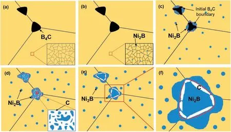
Fig.7.Schematic diagram of the in-situ reaction behavior the compacted Cu-Ni/B4C powder mixture during heating process.(a)initial state with a inset showing no reaction occurs,(b)starting of reaction and the formation of Ni2B at the grain boundary of Cu-Ni matrix,(c-d)processing of in-situ reaction,resulting in the increase of both size and number of Ni2B inside the Cu-Ni matrix along with a mixture of Ni2B and a-C at the primary powder boundary as shown in the insets,(e) final morphology of the Cu-Ni/B4C reaction system as well as (f) its high-magnification image to show the formation of the C-rich area around the position of initial B4C particles,respectively.
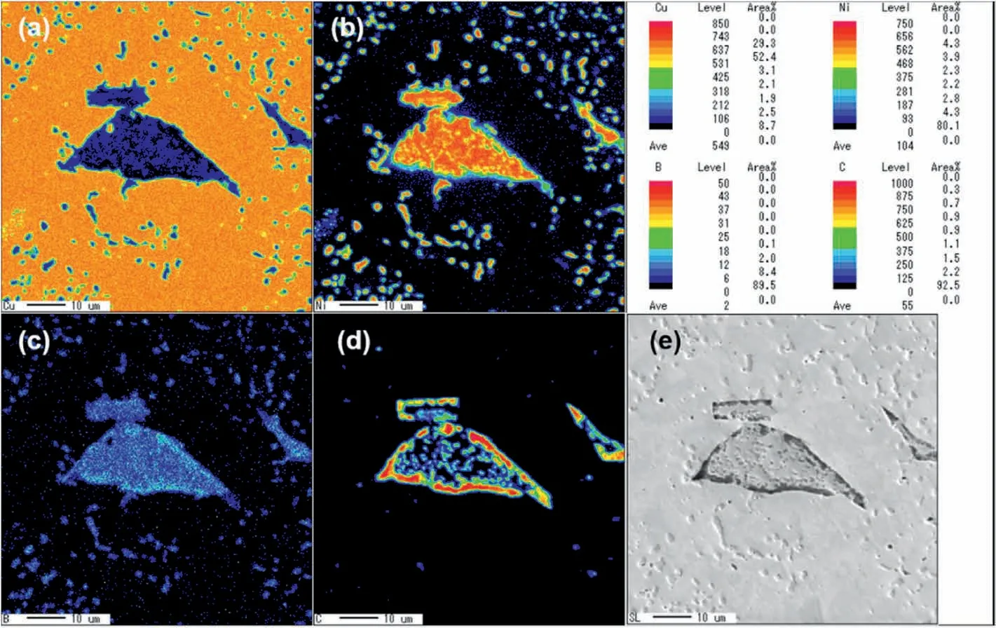
Fig.8.Elemental analysis of Cu-Ni/B4C powder system after SPS sintering at 900 °C for 1 h by EPMA mapping.(a-d)are elemental distribution of Cu,Ni,B and C,along with (e) secondary electronic image of the analyzed area,respectively.
Fig.8 shows the elemental distribution of the composites prepared by SPS from Cu-Ni and B4C powder mixture by EPMA mapping analysis.From the SEM image of the analysis area,a large number of small particles and irregular blocks could be found in the matrix,as show in Fig.8e.EPMA mapping shows that the matrix was mainly composed of Cu elements,while the particles were entirely composed of Ni and B elements,indicating that Ni2B particles dispersed in Cu matrix.The chemical composition and structure of the irregular blocks are complex.The outer layer was black and has a much higher C content than other areas,while the center was a monolithic block rich in Ni and B with dispersed black particles rich in C inside it,agreeing well with the result of TEM observation,namely a mixture of Ni2B and a-C.These experimental results also agree well with the final schematic diagram(Fig.7e),suggesting that the proposed reaction schematic process in Fig.7 is acceptable.
Up to present,the reaction process between Cu-Ni alloy powder and B4C particles has been summarized,but a question still remainsunknown,viz.why only Ni2B phase but no other Ni-B compounds formed inside the Cu-Ni matrix and B4C particles.Hence,it is necessary to study the thermodynamic conditions in these two different areas.Table 1 summarizes the potential chemical reactions according to the possible phases in Ni-B binary phase diagram [22],and the changes of Gibbs free energy (ΔG) at different temperatures ranging from 600 to 1000°C are also included,where the thermodynamic data come from Ref.[31,32].Apparently,the equations resulting in the formation of Ni2B phase always have the lowest ΔG in both areas,meaning that Ni2B would win from the competition among all the potential Ni-B compounds.Hence,Ni2B phase forms both the inner of Cu-Ni matrix and B4C particles,agreeing well with the experimental results.Such a result further demonstrates that using Eq.(1) for designing the chemical composition of Cu-Ni/B4C powder system is beyond doubt.
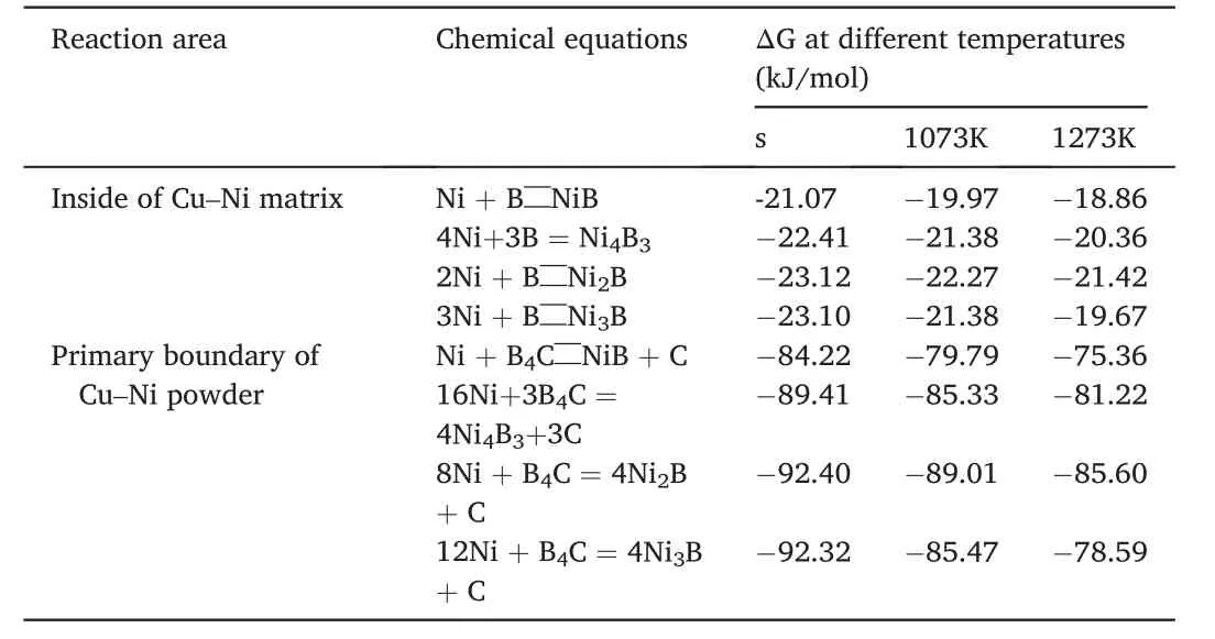
Table 1 Change of Gibbs free energy (ΔG) of potential reactions at different temperatures.
4.Conclusions
Based on the results of experimental investigations and theoretical calculations,the reaction behavior between Cu-Ni alloying powder and B4C particles under solid-state has been clarified in this paper,and the reaction can be described as the following stages:
1.B4C particles decompose into B and C atoms,and B atoms diffuse into Cu-Ni alloy and react with Ni to form Ni2B particles.The reaction occurs preferentially at the grain boundary of Cu-Ni matrix due to the fast diffusion rate,while the win out of Ni2B phase from the competition of all the Ni-B compounds is due to the most negative of Gibbs free energy(ΔG)change.
2.Ni atoms diffuse into B4C particles after the outward diffusion of B atoms,and react with B4C to form Ni2B at the edge of initial B4C particles because of the most negative ΔG.With the further increase of temperature and reaction time,B4C particles fully react,resulting in a large amount of Ni2B phase inside the Cu-Ni matrix and a mixture of Ni2B and amorphous C at the initial position of B4C particles.
3.Finally,when the reaction completes,the Ni2B particles at the initial position of B4C grow together while amorphous C is excluded and accumulated at the edge of this monolithic Ni2B block,since it cannot be accepted by Cu matrix in the form of solid solution.As a result,the microstructure of Cu-Ni/B4C system consists of Cu matrix with dispersed Ni2B particles inside it and monolithic Ni2B blocks surrounded by amorphous C at the primary powder boundary.
Declaration of competing interest
The authors declare that they have no known competing financial interests or personal relationships that could have appeared to influence the work reported in this paper.
Acknowledgements
The authors are grateful to National Natural Science Foundation of China of China (51871173/51875453),Key Laboratory Research Program of Shaanxi Educational Department (17JS082) and Opening Foundation of National United Engineering Laboratory for Advanced Bearing Tribology of Henan University of Science and Technology(201801)for financial support.
Appendix A.Supplementary data
Supplementary data to this article can be found online at https://do i.org/10.1016/j.pnsc.2020.12.002.
 Progress in Natural Science:Materials International2021年1期
- Progress in Natural Science:Materials International的其它文章
- Surface study of the reconstructed anatase TiO2 (001) surface
- Effect of Na+ in situ doping on LiFePO4/C cathode material for lithium-ion batteries
- Rational construction of NiCo2O4@Fe2O3 core-shell nanowire arrays for high-performance supercapacitors
- Electric transmission behavior of self-assembled Cu-W nano multilayers
- A hybrid hydrogel/textile composite as flame-resistant dress
- Improvement on hydrogen generation properties of Zr(BH4)4·8NH3
